1
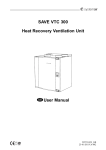
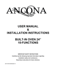
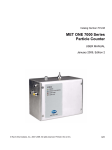
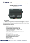
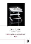
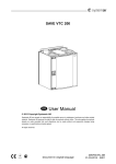
SAVE VTR 300/B
0
0
0 00
0
00
00
0
Installation and Service
Systemair is not liable or bound by warranty if these instructions are not
adhered to during installation or service.
© 2013 Copyright Systemair AB
Systemair AB can accept no responsibility for possible errors in catalogues, brochures and other printed
material. Systemair AB reserves the right to alter its products without notice. This also applies to products
already on order provided that such alterations can be made without sub sequential changes being
necessary in specifications already agreed.
All rights reserved.
Document in original language
208348-EN_GB
10-03-2014 A002
Contents
1 Declaration of Conformity ........................................................................................................... 1
2 Warnings................................................................................................................................... 2
3 About this document .................................................................................................................. 2
4 Product information.................................................................................................................... 2
4.1 General ........................................................................................................................... 2
4.2 Left and Right models ....................................................................................................... 3
4.3 Transport and storage....................................................................................................... 3
4.4 Technical data .................................................................................................................. 4
5 Installation................................................................................................................................. 7
5.1 Unpacking........................................................................................................................ 7
5.2 Where/how to install ......................................................................................................... 7
5.3 Installation procedure ....................................................................................................... 7
5.4 Condensation drainage..................................................................................................... 8
6 Commissioning .......................................................................................................................... 9
6.1 Control panel ................................................................................................................... 9
6.2 Start up wizard .................................................................................................................11
6.3 System curves .................................................................................................................13
6.4 Fan speed settings ...........................................................................................................17
6.5 Defrost level settings ........................................................................................................19
6.6 Programming the Week schedule ......................................................................................20
6.7 Ext/Force run ...................................................................................................................21
6.8 Extra functions .................................................................................................................21
6.9 Electrical connections .......................................................................................................22
6.10 External connections on the unit ......................................................................................23
7 Before starting the system ..........................................................................................................24
8 Operation ..................................................................................................................................24
8.1 Setting temperature ..........................................................................................................24
8.2 Manual setting of fan speed ..............................................................................................25
8.3 Manual and automatic summer mode ................................................................................25
8.4 Cool recovery...................................................................................................................25
8.5 Service menu overview.....................................................................................................26
9 Service......................................................................................................................................32
9.1 Warnings .........................................................................................................................32
9.2 Internal components .........................................................................................................33
9.3 Component descriptions ...................................................................................................34
9.4 Trouble shooting...............................................................................................................36
9.5 Replacing rotor drive belt ..................................................................................................38
9.6 Type label ........................................................................................................................39
1 Declaration of Conformity
Manufacturer
Systemair AB
Industrivägen 3
SE–739 30 Skinnskatteberg SWEDEN
Office: +46 222 440 00 Fax: +46 222 440 99
www.systemair.com
hereby confirms that the following product:
Heat recovery ventilation unit: SAVE VTR 300/B
(The declaration applies only to product in the condition it was delivered in and installed in the facility in
accordance with the included installation instructions. The insurance does not cover components that are
added or actions carried out subsequently on the product).
Comply with all applicable requirements in the following directives:
• Machinery Directive 2006/42/EC
• Low Voltage Directive 2006/95/EC
• EMC Directive 2004/108/EC
The following harmonized standards are applied in applicable parts:
EN ISO 12100:2010
Safety of machinery - General principles for design - Risk assessment and risk
reduction
EN 13857
Safety of machinery – Safety distances to prevent hazard zones being reached
by upper or lower limbs
EN 60 335-1
Household and similar electrical appliances – Safety Part 1: General requirements
EN 60 335-2-40
Safety of household and similar electrical appliances – Part 2-40: Particular
requirements for electrical heat pumps, air-conditioners and dehumidifiers
EN 60529
Degrees of protection provided by enclosures (IP Code)
EN 62233
Measurement methods for electromagnetic fields of household appliances and
similar apparatus with regard to human exposure
EN 50 106
Safety of household and similar appliances – Particular rules for routine tests
referring to appliances under the scope of EN 60 335-1 and EN 60967
EN 61000-6-2
Electromagnetic compatibility (EMC) – Part 6-2: Generic standards – Immunity
for industrial environments
Electromagnetic compatibility (EMC) – Part 6-3: Generic standards – Emission
standards for residential, commercial and light-industrial environments
EN 61000-6-3
The complete technical documentation is available.
Skinnskatteberg, 10-03-2014
Mats Sándor
Technical Director
SAVE VTR 300/B
208348
Installation and Service
1
Systemair AB
2 Warnings
The following admonitions will be presented in different sections of the document:
Danger
• Make sure that the mains supply to the unit is disconnected before performing any maintenance or
electrical work!
• All electrical connections and maintenance work must be carried out by an authorized installer and
in accordance with local rules and regulations.
Warning
• The system should operate continuously, and only be stopped for maintenance/service.
• The installation of the unit and complete ventilation system must be performed by an authorized
installer and in accordance with local rules and regulations.
• Beware of sharp edges during mounting and maintenance. Use protective gloves.
• Although the Mains supply to the unit has been disconnected there is still risk for injury due to rotating
parts that have not come to a complete standstill.
• Make sure that filters are mounted before starting the unit.
• This product must only be operated by a person which has suitable knowledge or education within
this field or carried out with the supervision of a suitably qualified person.
Caution
• Do not connect tumble dryers to the ventilation system.
• Duct connections/duct ends must be covered during storage and installation.
3 About this document
This installation manual concerns air handling unit type SAVE VTR 300/B manufactured by Systemair AB.
The manual consists of basic information and recommendations concerning the design, installation,
start-up and operation, to ensure a proper fail-free operation of the unit.
The key to proper and safe operating of the unit is to read this manual thoroughly, use the unit according to
given guidelines and adhere to all safety requirements.
4 Product information
4.1 General
The SAVE VTR 300/B is a heat recovery ventilation unit, with a built in rotating heat exchanger. The SAVE
VTR 300/B is suitable for houses with up to 240 m2 heated living area.
The SAVE VTR 300/B supplies filtered outdoor air to residential areas and extract air from bathroom,
kitchen and wet rooms. SAVE VTR 300/B is equipped with a 1670 W electrical re-heater battery.
SAVE VTR 300/B
208348
Installation and Service
2
Systemair AB
4.2 Left and Right models
There are two model options, right (R) and left (L) model. The different models are recognized by the
placing of the internal components and the supply air outlet, which is situated on left side of the unit on an
(L) unit and on the right hand side on an (R) unit.
Note:
This document describes a left (L) model. The inside of a right (R) model is mirrored.
4.3 Transport and storage
The SAVE VTR 300/B should be stored and transported in such a way that it is protected against physical
damage that can harm panels etc. It should be covered so dust, rain and snow cannot enter and damage
the unit and its components.
The appliance is delivered in one piece containing all necessary components, wrapped in plastic on a
pallet for easy transportation.
SAVE VTR 300/B
208348
Installation and Service
3
Systemair AB
4.4 Technical data
4.4.1 Dimensions and Weight, L model
B
C
A
D
I
J
H
G
E F
T
M
N
K
L
O P
R
S
Ø125
V
U
Ø160(4)
Fig. 1 Dimensions and weight, L model
Measures in mm and weight in kg.
A
B
C
D
E
F
G
H
I
J
K
762
4851
4232
842
804
824
758
405
258
97
121
L
M
N
O
P
R
S
T
U
V
Weight
206
255
104
136
216
303
490
788
1206
27
66
1.
2.
Including hatch
Including bracket
SAVE VTR 300/B
208348
Installation and Service
4
Systemair AB
4.4.2 Dimensions and Weight, R model
A
B
C
E F
D
T
G
H
I
M
N
J
R
P O
K
L
S
V
Ø125
U
Ø160(4)
Fig. 2 Dimensions and weight, R model
Measures in mm and weight in kg.
A
B
C
D
E
F
G
H
I
J
K
762
4861
4232
842
804
824
758
354
255
104
206
L
M
N
O
P
R
S
T
U
V
Weight
311
258
97
141
216
296
490
789
1206
28
66
1.
2.
Including hatch
Including bracket
SAVE VTR 300/B
208348
Installation and Service
5
Systemair AB
4.4.3 Duct connections
L
R
Fig. 3 Duct connections
Position
Description
R
Right hand model (Supply air connection is situated on the right hand side of the unit
viewed from the front)
L
Left hand model (Supply air connection panel is situated on the left hand side of the
unit viewed from the front)
Symbol
Description
Symbol
Description
Supply air
Outdoor air
Exhaust air
Extract air
Symbol
Description
Cooker hood air
4.4.4 Power consumption and fuse size
Re-heater
1670 W
Fans
176 W
Total power consumption
1846 W
Fuse
10 A
SAVE VTR 300/B
208348
Installation and Service
6
Systemair AB
5 Installation
This section describes how to install the unit correctly. To ensure a proper and fail-free operation, it is
important that the unit is installed according to these instructions.
5.1 Unpacking
Verify that all ordered equipment are delivered before starting the installation. Any discrepancies from the
ordered equipment must be reported to the supplier of Systemair products.
5.2 Where/how to install
The SAVE VTR 300/B should preferably be installed in a separate room (e.g. storeroom, laundry room
or similar.).
When choosing the installation position, consideration must be taken that the unit requires regular
maintenance. Leave free space for opening of the front hatch in order to perform service and maintenance
on components inside the unit.
The SAVE VTR 300/B is supplied with approximately 1 m cable and plug for 230V, single phase earthed
connection placed at the bottom of the unit.
Recommended installation location for the outdoor air intake is the northern or eastern side of the building
and with a distance to openings for discharge of stale ventilation air, kitchen ventilator, central vacuum
system, waste water drainage and other pollution sources like exhaust from traffic etc. Stale discharge
air should ideally be led via a roof unit to the outside and with a good distance to any outdoor air intake,
windows etc.
5.3 Installation procedure
Note:
It is recommended to remove the heat exchanger before the installation to make the unit lighter. The heat
exchanger weighs about 14 kg. How to remove the heat exchanger, see chapter 5.3.1 steps 1 through 3.
1. Prepare the surface where the unit is to be mounted. Make sure that the surface is flat, vertical
and that it supports the weight of the unit. Perform the installation in accordance with local rules
and regulations.
2. Fit the mounting bracket (1) with the anti-vibration
pad (2) to the wall with enclosed screws. Use
appropriate holes to screw the bracket firmly to
the wall. Bottom side of bracket should be 40
mm (H) below top of unit position.
Note:
Make sure that the mounting bracket is
completely horizontal once mounted on the wall.
Check with a spirit level.
SAVE VTR 300/B
208348
Installation and Service
7
Systemair AB
3. Lift the unit in place
Warning
Beware of sharp edges during mounting and
maintenance. Use protective gloves.
Consider the unit weight when mounting!
Note:
Make sure that the unit is completely vertical
and horizontal once mounted on the wall. Check
with a spirit level.
4. Connect the unit to the duct system. Make sure that all necessary accessories are used to create a
functional ventilation solution.
Warning
The installation of the unit and complete ventilation system must be performed by an authorized
installer and in accordance with local rules and regulations.
5. Remount the heat exchanger if it was removed before the installation. See chapter 5.3.1 steps 4 and 5.
5.3.1 How to remove and remount the heat exchanger
1. Open the front hatch.
2. Disconnect the heat exchanger power supply and the rotor sensor. Both cables are found beside the
heat exchanger.
3. Pull out the heat exchanger. Some force may be needed.
4. Remount the heat exchanger. Don’t forget to reconnect the heat exchanger power and sensor cables.
5. Close and lock the front hatch.
5.4 Condensation drainage
In general no condensation drainage is needed for rotational heat exchangers at dry conditions. However,
if a lot of humid air is present in the residence, a condensation drainage might be needed. Drainage
connection is available as an accessory and can be ordered seperate. Installation instructions for the
drainage are enclosed in the drainage pipes delivery.
Note:
The drainage connection is plugged in the bottom of the unit at delivery. To use the drainage: remove the
rubber seal and and connect the drainage pipe. Connect the drainage pipe to the sewer. The water can
not be led straight to the sewer without a water trap.
SAVE VTR 300/B
208348
Installation and Service
8
Systemair AB
6 Commissioning
Connect the unit electrically to the mains with the enclosed plug.
6.1 Control panel
The control panel is used to make the necessary adjustments.
1
3
2
4
Fig. 4 Control panel
Position
Description
Explanation
1
Display
Shows symbols, menus and settings
2
SELECTION knob
Move through the menu lists or change settings and
values by turning the knob left or right
3
CONFIRM button
Confirm menu choices or settings by pressing the button
4
BACK button
Step back in the menu levels and to abort an initiated
parameter change and restore the original value by
pressing the button
SAVE VTR 300/B
208348
Installation and Service
9
Systemair AB
6.1.1 Display symbols
Symbol
Description
Explanation
Temp
Illustrates the current set temperature. The temperature
setpoint is set in 6 steps (from completely empty to filled
symbol).
Turn the SELECTION knob to choose temperature.
Press CONFIRM to save the setting.
Fan speed
Illustrates the current fan speed. The fan speed can be
set manually in 4 steps: Off, Low, Nom and High.
Turn the SELECTION knob to choose fan speed.
Press CONFIRM to save the setting.
A. Ventilation off.1
B. Low ventilation: Can be used when leaving the
building for a longer period
C. Nominal ventilation: Will give required air change
under normal conditions.
D. Maximum ventilation: To increase the airflow if
necessary.
1.
Service
Press CONFIRM to access the service menu.
Alarm
Press CONFIRM to access the alarm list.
The fan can be set to OFF by activating manual fan stop. See service menu description under functions.
Note:
It is not recommended to activate manual fan stop (set fan to OFF) in standard households.
If manual fan stop is activated, the unit should be provided with dampers in exhaust and fresh air ducts to
avoid cold draught and risk of condensation when the unit has been stopped.
SAVE VTR 300/B
208348
Installation and Service
10
Systemair AB
6.2 Start up wizard
The Start up Wizard is a step-by-step configuration tool that starts automatically when the SAVE VTR
300/B is started for the first time or when:
• a factory reset is performed
• a new print card is installed (spare part)
In this case the unit type must be entered ( SAVE VTR 300/B )
The fan speed in the Start up wizard can be set by either l/s or a percentage with the Fan control.
• If Airflow is chosen, the settings will be in l/s and system curves are selected.
• If Speed is chosen, the settings will be in percentage. System curves are not selectable.
6.2.1 Procedure
1. Turn the SELECTION knob to choose language and press
CONFIRM
Languages
Language ENGLISH
2. Choose unit type, this choice is only present if a new print card
is installed (spare part) or when a factory reset is performed.
Type
SAVE VTR 300/B
3. Set date and time
Time/Date YY/MM/DD
Date:
12/09/12
Time: 10:00
Weekday: Sat
4. Select heater: None/Electrical/Water
Heater
Note:
Heater:
None/Electrical/Water
This choice is available only after a factory reset, see chapter
6.2.2, or when a new print card is installed.
SAVE VTR 300/B
208348
Installation and Service
11
Systemair AB
5. Fan control.
Fan control, Airflow
Turn the SELECTION knob to select the type of fan control you
prefer, Airflow (l/s) or Speed (%) and press CONFIRM.
System curve
EF: 1–10
SF: 1–20
Commission by %, see step 7.
Note:
System curves are not selectable when Speed is chosen.
Note:
Before setting the system curve, see chapter 6.3 for details.
This function is implemented in the unit to compensate the flow
values for different system pressures.
Supply Fan (SF): Total value range: 1–20. For F7 type filter:
1–10, forG3 type filter: 11–20.
Default curve: 2
Extract Fan (EF): Value range: 1–10
Default curve: 2
Note:
The factory installed filters are of filter quality F7 for the supply air
and G3 for the extract air filter.
Air filters are accessories and can be obtained from the installer
or wholesaler.
The filter type is labelled on the top of the filter.
6. Here it is possible to change the Nominal/High/Low airflow on
the Extract and Supply air fans. Airflow in l/s.
Airflow l/s
EF
SF
Nom
82
82
When settings are done, press CONFIRM.
High
100
100
Low
49
49
Speed %
EF
SF
Nom
50
50
High
100
100
Low
25
25
7. Here it is possible to change the Nominal/High/Low fan speed
on the Extract and Supply air fans. Fan speed in %. System
curves not selectable.
When settings are done, press CONFIRM.
SAVE VTR 300/B
208348
Installation and Service
12
Systemair AB
6.2.2 Perform Factory reset
How to perform a factory reset if necessary:
1. Enter the service menu by selecting the service
symbol in the display and press ENTER.
2. Go to password and enter the password,
default 1111
Use the SELECTION knob for each digit and
ENTER with the ENTER button after each set digit
and choose NO for the system not be locked.
Password
Password XXXX
Locked YES/NO
3. Go to Functions and select Factory Reset
Functions
Factory reset
4. Turn the SELECTION knob so YES is shown
and press ENTER.
Factory reset
Really reset?
5. ACCEPTED is shown in the display window
YES/NO
ACCEPTED
6. The Start up Wizard starts after approximately
10 seconds
6.3 System curves
A system requires different pressures at different airflows, which can be represented by a system curve.
The intersection between the system line and the fan curve, is the unit's working point. It is showing the
airflow the system is going to have. Every change in the pressure of the ventilation system, will give
rise to a new system curve.
The K-factor is a constant that is the same through out one and the same system curve. If the K-factor and
the system pressure is known, the airflow can be calculated. If the real pressure drop in the system is
larger or smaller than calculated, the working point and the airflow will be different than expected.
SAVE VTR 300/B
208348
Installation and Service
13
Systemair AB
6.3.1 Supply air, F7 type filter
700
10 V
600
10
500
9
8
7,1 V
400
Pa
7
6
300
5
4
5V
200
3
2
100
3V
1
0
0
20
40
60
80
100
120
140
l/s
Fig. 5 Supply air system curves, F7 type filter
System curve
K-factor [l/s]
1
18,03
2
9,22
3
7,49
4
5,82
5
4,63
6
3,70
7
2,93
8
2,28
9
1,73
10
1,26
SAVE VTR 300/B
208348
Installation and Service
14
Systemair AB
6.3.2 Supply air, G3 type filter
700
10 V
600
20
500
19
18
7,1 V
400
Pa
17
16
300
15
14
5V
200
13
12
100
3V
11
0
0
20
40
60
80
100
120
140
l/s
Fig. 6 Supply air system curves, G3 type filter
System curve
K-factor [l/s]
11
19,03
12
9,68
13
7,83
14
6,02
15
4,81
16
3,87
17
3,05
18
2,37
19
1,81
20
1,32
SAVE VTR 300/B
208348
Installation and Service
15
Systemair AB
6.3.3 Extract air, G3 type filter
700
10 V
600
10
9
500
8
7,1 V
7
400
Pa
6
300
5
4
5V
200
3
2
100
3V
1
0
0
20
40
60
80
100
120
140
l/s
Fig. 7 Extract air system curves, G3 type filter
System curve
K-factor [l/s]
1
16,47
2
9,04
3
7,03
4
5,40
5
4,29
6
3,41
7
2,71
8
2,12
9
1,64
10
1,20
SAVE VTR 300/B
208348
Installation and Service
16
Systemair AB
6.4 Fan speed settings
The fan speed can be set by either l/s, m3/h or a percentage.
• If Airflow is chosen in the service menu, the settings will be in l/s and system curves are selected.
• If Speed is chosen in the service menu, the settings will be in percentage. System curves are not
selectable.
The fan speed may be adjusted in four steps; off, low, nominal and high. These settings control the output
signals to the supply- and extract fans. The factory setting on each speed steps are:
• Off: 0 l/s
• Low: 49 l/s or 25 %.
• Nom: 82 l/s or 50 % (at approximately 80 Pa).
• High: 100 l/s or 100 %.
These levels are possible to change in the service level. See service menu overview (chapter 8.5) under
functions.
Note:
It is not recommended to activate manual fan stop (set fan to OFF) in standard households.
If manual fan stop is activated, the unit should be provided with dampers in exhaust and fresh air ducts to
avoid cold draught and risk of condensation when the unit has been stopped.
The fan can be set to OFF by activating manual fan stop. See service menu overview (chapter 8.5)
under functions.
SAVE VTR 300/B
208348
Installation and Service
17
Systemair AB
6.4.1 Setting the fan speed
1. Go to the service menu by using the SELECTION knob
2. Enter the service level by typing the password, default 1111.
Use the SELECTION knob for each digit and confirm with the
CONFIRM button after each set digit and choose "NO" for the
system not be locked.
Password
Password XXXX
Locked YES/NO
3. Go to: Functions
Functions
Choose: Fan control
—> Fan control
4. Turn the SELECTION knob to select the type of fan control you
prefer, Airflow (l/s or m3/h) or Speed (%) and press CONFIRM.
Fan control
Fan control by speed, see step 7.
Airflow
Speed
5. Fan control by Airflow l/s.
Fan control
When settings are done, press CONFIRM.
Airflow system curve
Choose system curve.
SF:4
6. Press BACK once the system curves has been set and go to
Airflow %.
Airflow
l/s
EF
SF
When settings are done, press CONFIRM.
Nom
82
82
High
100
100
Low
49
49
7. Fan control by Speed %
Speed %
EF
SF
When settings are done, press CONFIRM.
Nom
50
50
High
100
100
Low
25
25
SAVE VTR 300/B
208348
EF:4
Installation and Service
18
Systemair AB
6.5 Defrost level settings
The unit is equipped with an automatic defrost function that is activated when there is risk of icing in the
area around the heat exchanger. The setting 0-5 (table 1) determines how aggressive the defrosting will
be. Default factory setting is mode 0.
Note:
The heat exchanger should withstand low outdoor temperatures, but in those cases where icing can
occur please be aware of that the defrost setting will generate an under pressure in the building. Using
a fire place, be aware that there is a possible risk of smoke being extracted into the living areas due to
under pressure if defrosting is activated.
Table 1: Defrost levels
Defrost
mode
Relative humidity indoors1
0
Description
Defrosting is turned off
1
Minimum <20%
Dry areas, such as warehouse buildings with few people or
industrial buildings that don’t use water in their production
process.
2
Low 30% - 40%
Office buildings
3
Medium 40% - 60%
Apartments or houses with normal humidity2
4
High 60% - 80%
Apartments or houses with high humidity
5
Extremely high >80%
Buildings with very high humidity level.
1.
2.
Relative humidity in the extract air at cold outdoor temperatures.
In newly constructed houses it might be necessary with a higher defrost level during the first winter period.
6.5.1 Setting the defrost level
1. Go to the service menu by using the
SELECTION knob.
2. Enter the service level by typing the password,
default 1111. Use the SELECTION knob for each
digit and confirm with the CONFIRM button after
each set digit and choose "NO" for the system not
be locked.
Password
Password XXXX
Locked YES/NO
3. Go to: Functions
Functions
Choose: Defrosting
Defrosting
4. Set the mode, 0 – 5
Defrosting
Mode 0–5
SAVE VTR 300/B
208348
Installation and Service
19
Systemair AB
6.6 Programming the Week schedule
Set the week schedule according to below procedure:
1. Go to the service menu by using the
SELECTION knob.
2. Enter the service level by typing the password,
default 1111. Use the SELECTION knob for each
digit and confirm with the CONFIRM button after
each set digit and choose "NO" for the system not
be locked.
Password
Password XXXX
Locked YES/NO
3. Go to: Week program
Service
Week program
4. Choose Week program again.
Week program
Fan speed
5. Set week day and time you want the unit to
be in ON level. Two periods per day can be
programmed. The rest of the time the unit will be in
OFF level.
Week program
6. Go back to the previous dialogue frame with the
BACK button and go down to Fan speed.
Week program
Day:
Per 1:
Per 2:
MON
07:00 16:00
00:00 00:00
Fan speed
7. Set which fan speed the fan is supposed to be
running in the ON level, choose between Low,
Nom or High.
Set which fan speed the fan is supposed to be
running in the OFF level, choose between OFF,
Low, Nom or High.
Fan speed
On level: low/nom/high
Off level: off/low/nom/high
Note:
If an electrical re-heater battery is installed and
active and the unit is shut down from the control
panel, for example by choosing OFF. When the
unit is in OFF level in the week program, the fans
will continue to run for 3 minutes, to prevent the
heater from triggering the over heat protection
sensor, before they stop.
8. Step back with the BACK button until you reach
the main menu display
SAVE VTR 300/B
208348
Installation and Service
20
Systemair AB
6.7 Ext/Force run
It is possible to program extended time you want the unit to work under operation conditions other than
determined by the week schedule.
1. Go to the service menu by using the
SELECTION knob.
2. Enter the service level by typing the password,
default 1111. Use the SELECTION knob for each
digit and confirm with the CONFIRM button after
each set digit and choose "NO" for the system not
be locked.
Password
Password XXXX
Locked YES/NO
3. Go to: Ext/Force Run
Service
Ext/Force Run
4. Set the time in minutes the unit is to run in
extended/forced running mode. Value range:
0–240 minutes.
Ext/Force Run
Set the fan speed for this mode. Choose between
Low, Nom or High.
Default value: Nom.
Fan speed:
Minutes:
0
Nominal
6.8 Extra functions
The unit is equipped with a number of extra on/off functions which can be activated from external on/off
switches that can be connected to the digital inputs on the main print card (see wiring diagram).
The following possibilities are available:
• Digital inputs 1–3: By connecting on/off switches to these inputs it’s possible to choose 3 individual
fan speed settings in the control panel depending on a temporary need for the building (for example
lowering the extract air fan speed when an open fire place is used). See chapter 8.5.
DI 3, is prepared and already connected internally for easy access on the unit. See chapter 6.10.
• Digital input 4: Makes it possible to disable the integrated electrical re-heater
Activated input means that the electrical re-heater is disabled.
• Digital input 5: Activate the Extended/forced running function with a retractive switch. The function
overrides current fan speed settings and runs in forced mode according to the settings in Service ->
Ext/Force run. Choose between Low, Nom and High for this function.
The input is calculated based on the signals from an impulse-switch. If a standard switch is used, the
countdown of the set time starts when the switch is switched off.
• Digital input 7: Home/leave, switching on this input decreases the set-point for supply air-temp with
10°C. This function is used when the building is uninhabited for a longer period. This function is
however not working if the unit has been configured to operate with a hot water heater.
It is recommended to connect either of DI1, DI2 or DI3 in parallel with DI7. If DI7 is activated, set the
fans speed to min. Fan speed settings are done when configuring DI1, DI2 or DI3.
See menu options in “Service menu Overview” (chapter 8.5).
SAVE VTR 300/B
208348
Installation and Service
21
Systemair AB
6.9 Electrical connections
The SAVE VTR 300/B is wired internally from factory.
The electrical connection box can be found on the supply air outlet side of the unit behind a cover plate.
The print card (1) can easily be taken out from the unit.
1
Fig. 8 Print card position
6.9.1 Print card layout
The SAVE VTR 300/B is equipped with built-in regulation and internal wiring.
The figure shows the print card. See wiring diagram for more information.
8
9
3
2
10
5
1
4
7
6
11
Fig. 9 Print card
Position
Description
1
Main print card
2
Print card for electrical re-heater
3
Connection to external control panel (connected to unit casing)
SAVE VTR 300/B
208348
Installation and Service
22
Systemair AB
Position
Description
4
Mains supply connection between main print card and electrical re-heater print card
5
Terminals for AI 1–5 (temp sensors) and motor control
6
Terminals for external connections
7
Terminals for mains supply connections
8
Terminals for digital inputs (DI 1–7)
9
Terminals for internal control panel.
10
Terminals for regulated power supply to electrical re-heater
11
Modbus connection. See "User manual Modbus" for details.
6.9.2 External connections on the print card
Connection terminals for external equipment can be found on the main print card inside the electrical
connection box.
Fig. 10 External connections on the print card
Position
Description
Remark
1
Outdoor/exhaust air damper
Normally open, 230 V 1~, max 1 A
2
Outdoor/exhaust air damper
Reference
3
Outdoor/exhaust air damper
Normally closed, 230 V 1~, max 1 A
4
Sum alarm
Normally open, 24 V, max 1 A
5
Sum alarm
Reference
6
Sum alarm
Normally closed, 24 V, max 1 A
7
GND
Reference
8
Water cooler control signal (AO1)
0–10 V DC
9
GND
Reference
10
Water heater control signal (AO2)
0–10 V DC
11
GND
Reference
12
Damper (AO3)
Not used
6.10 External connections on the unit
Two of the connections on the main print card are wired to plugs on the unit casing:
• connection to an external control panel through a modular connector.
Maximum cable length: 50 m.
Cable type: Flat 4–conductor CEC Phone cable, or equivalent.
SAVE VTR 300/B
208348
Installation and Service
23
Systemair AB
• connection to DI 3 with possibility to configure the fan speeds individually through a potential free
on/off switch
0
Default settings: SF=High, EF=Low.
1
3
2
1. Cable glands
2. Connection to DI 3 through a potential free on/off switch
3. Connection to control panel
7 Before starting the system
When the installation is finished, check that:
• The unit is installed in accordance with the instructions
• The unit is correctly wired
• Outdoor and exhaust air dampers and silencers are installed and that the duct system is correctly
connected to the unit
• All ducts are sufficiently insulated and installed according to local rules and regulations
• Outdoor air intake is positioned with sufficient distance to pollution sources (kitchen ventilator exhaust,
central vacuum system exhaust or similar)
• All external equipment is connected
• The unit is correctly configured and commissioned
• The week schedule and fan speed settings are correctly programmed.
8 Operation
8.1 Setting temperature
The supply air temperature is set manually in 6 steps in the main menu display by choosing the
temperature symbol.
If an electrical or water re-heater is installed the temperature setpoints are:
12.0, 14.5, 17.0, 19.5 and 22.0 °C. Default value: 12.0 °C.
If the re-heater is deactivated, the temperature steps are:
15.0, 16.0, 17.0, 18.0 or 19.0 °C. Default value: 15.0 °C.
Each temperature step is illustrated by increasing the filling of the temperature symbol.
An unfilled temperature symbol is the 6th setpoint and will activate manual summer mode. See chapter 8.3
SAVE VTR 300/B
208348
Installation and Service
24
Systemair AB
8.2 Manual setting of fan speed
It is possible, at any time, to manually set the fan speed in the main menu display. By choosing the fan
symbol and confirming it is possible to increase or decrease the fan speed in the 4 steps: Off, Low,
Nom and High.
By doing so, you override the programmed week schedule for the unit until the end of the present time
period in the week program (chapter 6.6).
Warning
The fan can be set to OFF by activating manual fan stop. See service menu overview (chapter 8.5)
under functions.
8.3 Manual and automatic summer mode
Manual summer mode occurs if no temperature step is selected. The temperature symbol on the main
menu is then completely empty.
Te mp
If the electrical re-heater is activated, it will switch off during manual summer mode. Manual summer
mode goes automatically to step 1 (setpoint 12 °C) after two minutes if the supply air temperature is
+5 °C or below.
If a water heater battery is installed and activated, the manual summer mode goes automatically to step 1
(setpoint 12 °C) if the outdoor air or supply air temperature is +5 °C or below.
The unit will automatically alternate between winter operation with heat recovery and summer operation
without heat recovery.
8.4 Cool recovery
If the outdoor air is warmer than the extract air and the supply air is above the setpoint, cool recovery
occurs. This condition blocks the heat regulation process.
SAVE VTR 300/B
208348
Installation and Service
25
Systemair AB
8.5 Service menu overview
Enter the service menu by selecting the service symbol in the display.
Menu Level 1
Menu Level 2
Service
Password
Password
Password XXXX
Locked YES/NO
Enter the service level
by typing 1111. Use the
SELECTION knob for each
digit and confirm with the
CONFIRM button after each
set digit. NO will unlock the
system and allow parameter
changes.
Service
Change
Password
Change
password
Actual XXXX
New
XXXX
Confirm XXXX
Set new password if
necessary.
Service
Filter
period
Filter period
Service
Time/Date
Menu Level 3
Explanation
In case the new password
would be forgotten or
misplaced it’s still possible
to enter the service level by
writing 8642. This overrides
the earlier set password.
Shows selected time interval
between filter change.
Time to
replace:
12month
Set Reset of the filter period
to YES after completed filter
change.
Reset NO/YES
Set time between filter
changes.
Time/Date
YY/MM/DD
Shows current set date and
time.
Date:
12/09/12
Set Correct date and time.
Time: 10:00
Weekday: Sat
Service
Ext/Force
Run
Use this dialogue frame to
program extended time you
want the unit to work under
operation conditions other
than determined by the week
schedule.
Ext/Force Run
Minutes:
0
Fan speed:
Nominal
Shows set time for
extended/forced running.
Shows Set fan speed.
Set the time that the unit is to
run in extended/forced mode.
Value range: 0–240 minutes.
Set the fan speed for this
mode. Choose between Low,
Nom or High.
Default value: Nom.
SAVE VTR 300/B
208348
Installation and Service
26
Systemair AB
Menu Level 1
Menu Level 2
Menu Level 3
Explanation
Service
Week
program
Week program
Week program
Week program
Day:
Per 1:
Per 2:
Program how you want the
unit to operate according
to the week schedule. It’s
possible to set 2 periods per
day.
MON
07:00 16:00
00:00 00:00
Set week day and time interval
for the time you want the unit
to be in ON mode.
Week program
Fan speed
Fan speed
On level: low/nom/high
Off level:
off/low/nom/high
Use this dialogue frame to
determine the ON and OFF
function for the fans in the
week schedule.
Set ON level.
Choose between Low, Nom or
High.
Default value: Nom
Set OFF level.
Choose between OFF, Low,
Nom or High.
Default value: Low.
Service
Fan speed
log
Fan speed log
Use this dialogue frame to see
how the fans have operated
during the time (h) they have
been active.
Level: 1–5
Reset: NO/YES
SF: 140
/140
EF: 140
/140
The speeds are shown in 5
different levels:
• Level 1: 0%
• Level 2: 1 – 29%
• Level 3: 30 – 44%
• Level 4: 45 – 59%
• Level 5: 60 – 100%
Choose between the levels
to see the time in hours the
fans have been active in the
different levels.
Reset Yes resets the SF and
EF time in the left column for
all levels. The right column
continues to count ahead and
can not be reset.
Note:
Factory reset (see
Functions –>Factory
reset) will not affect this
function
SAVE VTR 300/B
208348
Installation and Service
27
Systemair AB
Menu Level 1
Menu Level 2
Menu Level 3
Explanation
Service
Functions
Functions
Heater/Cooler
Heater/Cooler
Heater:
None/Electrical/Water
Cooler: None/Water
Use this dialogue frame to set
up the unit for heating and/or
cooling.
Set Heater to None, Electrical
or Water.
Set Cooler to None or Water.
Functions
Frost protection
Frost
protection
Alarm limit:
Functions
System curve
System curve
EF: 1–10
SF: 1–20
7°C
Shows current set frost
protection alarm limit in °C for
the installed water coil.
Set Alarm limit in °C.
Default value: 7°C.
This function is to compensate
the flow values for different
system pressures.
See chapter 6.3
Functions
Fan control
Fan control
Airflow
Speed
Fan control
Airflow
l/s
EF
SF
Airflow
Nom
82
82
High
100
100
Low
49
49
Select the type of fan control
you prefer. Fan control by l/s
or %
Use this dialogue frame to
set the fan speed in l/s. The
speed can be set individually
for each fan
EF: Extract fan,
SF: Supply fan
Set the fan speed for EF and
SF for each step (Low, Nom,
and High.
Fan control
Airflow unit
Airflow unit
l/s
m3/h
Fan control
Speed %
EF
SF
Nom
50
50
High
100
100
Low
25
25
Speed
Default value: l/s
Use this dialogue frame to
set the fan speed in %. The
speed can be set individually
for each fan
EF: Extract fan,
SF: Supply fan
Set the fan speed for EF and
SF for each step (Low, Nom,
and High.
Functions
Manual fan stop
Manual fan
stop
Allow manual fan stop
Y/N
Set if it should be possible
to turn off the fans in the unit
manually from the control
panel.
Chose between Y and N.
If Y is selected the fans can
be turned off by turning the
SELECTION knob to empty
fan
SAVE VTR 300/B
208348
Installation and Service
28
Systemair AB
Menu Level 1
Menu Level 2
Menu Level 3
Explanation
Functions
Analog input
Shows analogue inputs from
active temperature sensors.
Analog input
1:
2:
3:
4:
5:
SS 20.0
ETS 23.0
Unused
OT/FPS 20.0
OS 10.5
SS: Supply air temp sensor.
ETS: Extract air temp sensor.
OT/FPS: Over heat protection
sensor/Frost protection
sensor.
OS: Outdoor air temp sensor.
Functions
Analog output
Analog output
A01 auto/man/off 0.0V
A02 auto/man/off 7.3V
A03 auto/man/off 0.0V
Shows current analogue
outputs in 0–10 V to hot/cold
water actuator.
Set AO1(Analogue output to
hot water actuator) to auto,
man or off.
Default value: auto.
Set AO2 (Analogue output to
cold water actuator) to auto,
man or off.
Default value: auto.
AO3 Not used.
Functions
Digital input
Digital input
DI1
DI2
DI3
DI4
DI5
DI6
DI7
ON/OFF
ON/OFF
ON/OFF
ON/OFF
ON/OFF
ON/OFF
ON/OFF
Shows current setting of the
digital inputs ON or OFF
DI1: Fan configuration
DI2: Fan configuration
DI3: Fan configuration
DI4: Heater deactivated
DI5: Extended/forced running
DI6: Rotor sensor
DI7: Home/leave
Functions
Config DI 1–3
Config DI 1–3
Default:
1 SF high EF high
2 SF low EF low
3 SF high EF low
Use this dialogue frame to
set how you want the fans
to react to 3 different digital
inputs when they are switched
on (the settings in the column
to the left are examples).
Potential free switches need
to be connected physically to
terminals on the main print
card to obtain the different
functions. See the wiring
diagram for more information.
Set the supply air fan (SF) and
extract air fan (EF) individually
to off, low, nom or high for
digital inputs 1–3
SAVE VTR 300/B
208348
Installation and Service
29
Systemair AB
Menu Level 1
Menu Level 2
Menu Level 3
Explanation
Functions
DI 4–7
DI 4–7
4
5
6
7
DI 4–7 are default set from
factory and can’t be changed
by the user. Below follows
a short description of each
function.
Stop heat
Ext run
Rotor
Home/Leave
DI4: Makes it possible
to disable the integrated
electrical re-heater. Activated
input means that the electrical
re-heater is deactivated.
DI5: Activate the
Extended/forced running
function. The function
overrides current set fan
speed settings and runs
according to the settings in
Service-> Ext/Force
run. Choose between Low,
Nom and High for this function.
The input is calculated based
on the signals from an
impulse-switch. If a standard
switch is used, the countdown
of the set time starts when the
switch is switched off.
DI6: Rotor sensor.
DI7: Switching on this input
decreases the supply air temp
set point with 10°C.
This function is used when the
building is uninhabited for a
longer period.
It is recommended to connect
DI7 and DI1 or DI3 in parallel.
If DI7 is activated, set the
fans speed to min. Fan
speed settings are done when
configuring DI1/DI3.
Note:
The “Home/Leave” function is
not working if Water heater is
activated.
SAVE VTR 300/B
208348
Installation and Service
30
Systemair AB
Menu Level 1
Menu Level 2
Menu Level 3
Explanation
Functions
Digital output
Digital output
1:
2:
3:
4:
5:
6:
Shows The current settings
of digital outputs 1–6 (the
settings in the column to the
left are examples).
SF 67%
EF 67%
Rot ON/OFF
ALARM Y/N
Dmp Y/N
Reheater Y/N
1: SF 67%: Current set speed
of the supply air fan (shown as
percentage of the maximum
speed).
2: EF 67% Current set speed
of the extract air fan (shown as
percentage of the maximum
speed).
3: Shows if the rotor is active
or not.
4: Alarm Y/N: Indicates if the
sum. alarm is active or not
5: Dmp OFF: Outdoor/exhaust
air damper is on or off.
6: Reheater Y/N: Indicates
if the electrical re-heater is
active or not.
Functions
Defrosting
Defrosting
Mode 0–5
Functions
Modbus
Modbus
Address 1
Baud 9600/19200
Parity None/Even/Odd
Use this dialogue frame to set
how aggressive you want the
defrosting function to operate
(see chapter 6.5).
Information about Modbus
communication and variables
can be found in the Modbus
user manual for residential
units in the online catalogue at
www.systemair.com.
Functions
Factory reset
Factory reset
Really reset?
Use this dialogue frame to
return to factory settings.
YES/NO
Set YES or NO
Note:
This will erase all your
personal settings that have
been done for the unit.
Service
Language
Languages
Use this dialogue frame to
return to select your local
language.
Language
ENGLISH
Set Language by turning the
SELECTION knob.
SAVE VTR 300/B
208348
Installation and Service
31
Systemair AB
Menu Level 1
Menu Level 2
Service
Versions
Version SAVE
VTR 300/B
Menu Level 3
Shows current software
versions
CD EC
Appl. 1.08.00
3.16.00
Boot 1.00.01
1.01.00
Service
Alarms
Explanation
Note:
The software versions are just
an example and may differ in
a specific unit.
Alarms
Shows the alarm list and
which alarms that have been
triggered (indicated by Y). See
alarm list (chapter 9.4.1)
Fan Y
EmT/Frost N
Damp Y
Pb Fail N
Temp N
Filter Y
9 Service
9.1 Warnings
Danger
• Make sure that the mains supply to the unit is disconnected before performing any maintenance or
electrical work!
• All electrical connections and maintenance work must be carried out by an authorized installer and
in accordance with local rules and regulations.
Warning
• The system should operate continuously, and only be stopped for maintenance/service
• Although the mains supply to the unit has been disconnected there is still risk for injury due to rotating
parts that have not come to a complete standstill
• Beware of sharp edges during maintenance. Use protective gloves
• Make sure that filters are mounted in their place before running the system
• This product must only be operated by a person which has suitable knowledge or education within
this field or carried out with the supervision of a suitably qualified person.
SAVE VTR 300/B
208348
Installation and Service
32
Systemair AB
9.2 Internal components
1
2
16
15
3
4
14
5
13
6
12
7
11
10
8
9
Fig. 11 Internal components
Position Description
1
Mounting bracket
2
External connections
3
Extract air sensor
4
Overheat protection sensor
5
Internal electrical re-heater
6
Extract air filter
7
Main print card
8
Supply air fan
9
Rotor motor and belt pulley
10
Rotating heat exchanger
11
Heat exchanger drive belt
12
Rotor sensor
13
Supply air filter
14
Extract air fan
15
Outdoor air sensor
16
Supply air sensor
SAVE VTR 300/B
208348
Installation and Service
33
Systemair AB
9.3 Component descriptions
9.3.1 Fans
The fans have external rotor motors of EC type which can be steplessly controlled individually 20–100%.
The motor bearings are life time lubricated and maintenance free. It is possible to remove the fans for
cleaning, see “User Manual” for more information.
9.3.2 Filters
The factory installed filters are of filter quality F7 for the supply air and G3 for the extract air filter. The filters
need to be replaced when polluted. New sets of filters can be acquired from your installer or wholesaler.
Filter quality G3 can be installed for supply air filtering.
The filter type is labelled on the top of the filter
Note:
If type G3 filters are used instead of F7 , the system curve for Supply Fan (SF) must be changed:
For G3 type filter: 11–20, for F7 type filter: 1–10. See chapter 6.3.
9.3.3 Heat exchanger
SAVE VTR 300/B is equipped with a rotating heat exchanger. Required supply air temperature is therefore
normally maintained without adding additional heat.
The heat exchanger is removable for cleaning and maintenance, see “User Manual” for more information.
9.3.4 Print card
The main print card controls the functions and set temperatures of the unit.
It is possible to connect external accessories to terminals on the print card and also communication to
BMS (Building Management System) Modbus communication via RS-485. See wiring diagram for more
information.
9.3.5 Temperature sensors
Four temperature sensors (NTC, 10 kΩ at 25°C) are included in the unit from factory and positioned in the
corresponding air chambers.
The sensors are connected to the main print card. See wiring diagram for more information.
9.3.6 Electrical Re-heater battery
The re-heater battery is positioned in the supply air chamber.
The re-heater is activated by a relay and switches on if the supply air temperature is 2 K lower than the set
point and switches off if one or more of the following conditions are met:
1. If the supply air temperature is more than 2 K above the set point.
2. If the over heat protection is activated or the sensor is malfunctioning.
3. If the emergency thermostat is triggered or broken.
4. If the supply air sensor is in error state.
5. If the supply air fan is not running.
6. If the heater is set to disabled in the menu.
SAVE VTR 300/B
208348
Installation and Service
34
Systemair AB
9.3.7 Overheat protection reset button
If the supply air temperature is low, it can indicate that the over heat protection is triggered. The overheat
protection can be reset by pressing the reset button (1).
1
Fig. 12 Overheat protection reset button
9.3.8 Water Re-heater battery
A water re-heater battery (optional), which can be acquired as an accessory, can be controlled by the
analog output WH (0-10 V DC). The water heater uses AI 4 for frost protection (OT, “Over heat protection”,
changes to FPS , Frost protection in the menu).
The frost protection sensor should then be a strap on surface sensor situated on the return water tube.
Sensor type: TG-A130
The supply air sensor (SS) at AI 1 must be replaced with a duct sensor which can be acquired as an
accessory. Sensor type: TG-K360. See wiring diagram for more information.
Only electrical or water re-heater is allowed, i.e. if a water re-heater is selected, the electrical re-heater is
deactivated and vice versa.
Note:
If a water re-heater battery is installed we strongly recommend you to also install an outdoor air damper
with a spring return actuator.
9.3.9 Water Cooler
A water cooler (optional) can be acquired as an accessory and be controlled by the unit. If a water cooler
is installed the supply air sensor (SS) at AI 1 must be replaced with a duct sensor which can be acquired
as an accessory. Sensor type: TG-K360. See wiring diagram for more information.
SAVE VTR 300/B
208348
Installation and Service
35
Systemair AB
9.4 Trouble shooting
A warning triangle with text in the display indicates an alarm. Turn menu selector to the warning triangle
and press confirm twice to view the alarm.
If problems should occur, please check the items below before calling your service representative.
Malfunction
Action
Fans do not start
1. Check the display for alarms.
2. Check fuse for main power supply in the distribution box for the building
and all the quick connectors are connected in the unit (quick connectors
for supply and extract air fans).
3. Check that the week program is in ON mode. The week program might be
in OFF mode with the fan speed set to OFF (chapter 6.6)
4. Check if one of the digital inputs 1–3 (DI 1–3) is active and set to off. This
would force one or both fans to stop depending on the setup (chapter 8.5).
Reduced airflow
1. Check the display for alarms.
2. Check setting of fan speed in the control panel (chapter 6.1.1).
3. Check week program (chapter 6.6).
4. Check if one of the digital inputs 1–3 (DI 1–3) is active and set to off. This
would force one or both fans to stop depending on the setup (chapter 8.5).
5. Check filters. Change of filters required?
6. Check diffuser/louver openings. Cleaning of diffusers/louvres required?
7. Check fans and heat exchange block. Cleaning required?
8. Check if the buildings air intake and roof unit (exhaust) have been clogged.
9. Check visible duct runs for damage and/or build up of dust/pollution.
The unit cannot be
controlled
(control functions are
stuck)
1. Reset control functions by pulling out the main power supply plug for
20-30 seconds.
2. Check the modular contact connection between the control panel and
the main print card.
SAVE VTR 300/B
208348
Installation and Service
36
Systemair AB
Low supply air
temperature
1. Check the display for alarms.
2. Check set supply air temperature in the control panel.
3. Check the analogue inputs in the service menu to verify that the temp
sensors are ok (chapter 8.5). Go to Functions > Analogue input
and verify the temperature readings from the temp sensors.
4. Check if the over heat protection thermostat is still alert. If necessary,
reset by pressing the reset button. See chapter 9.3.7.
5. Check if digital input 4 (DI 4) is set to off. This would force the electrical
re-heater battery to be switched off (chapter 8.5)
6. Check if the extract filter must be changed.
7. At very cold outdoor conditions an electrical pre heating battery might be
necessary. This can be acquired as an accessory.
At very cold outdoor conditions an electrical pre heating battery might be
necessary. This can be acquired as an accessory.
8. Check the balance between the supply and extract air
Noise/vibrations
1. Clean fan impellers.
2. Check that the screws holding the fans are tightened.
3. Check that the anti vibration pads are fitted at the bottom of the unit.
9.4.1 Alarm list
Alarm
Explanation
Do the following
Fan
Indicates error on either supply or
extract air fan.
The alarm is displayed in the control panel.
Check that quick connectors are connected for the
both fans.
Contact your installation company or place of
purchase.
EMT/Frost
Indicates triggered frost protection
(in case of installed water heating
battery) or triggered overheat
protection (in case of installed
electric re-heater battery).
A triggered frost protection alarm results in the
following:
• Both fans stop.
• Outdoor and exhaust air dampers closed.
• Water valve opens completely (10 V signal goes
out to the actuator).
The unit will restart once the water temperature
reaches +5°C above the set frost protection
temperature.
A triggered over heat protection gives an alarm in the
control panel.
Reset by pushing the reset button. See chapter 9.3.7.
If the problem continues contact your installation
company or place of purchase.
SAVE VTR 300/B
208348
Installation and Service
37
Systemair AB
Alarm
Explanation
Do the following
Rotor
Indicates a rotor malfunction.
The alarm is displayed in the control panel.
• If the rotating heat exchanger has stopped. Check
the rotor belt. See chapter 9.5
• If the heat exchanger is still rotating, check that the
quick connector for the sensor is connected and
that there is an air gap of 5-10mm between the
sensor and the magnet.
Adjust the gap if necessary.
If the alarm persists, the rotor sensor may be faulty.
Contact your installation company or place of
purchase.
PbFail
Temp
Filter
Error in connection with relay
card for the electrical re-heater (if
installed and activated).
The alarm is displayed in the control panel.
The overheat protection sensor,
automatic reset (ET2) may be
triggered due to high temperature.
For triggered ET2, wait 10–15 min. If the error
remains, contact your installation company or place
of purchase.
Malfunction in one or more of the
temperature sensors.
The alarm is displayed in the control panel.
Time for filter change.
The alarm is displayed in the control panel.
The heater will not be activated.
Contact your installation company or place of
purchase.
Change filter according to instructions in the user
guide.
9.5 Replacing rotor drive belt
Danger
• Make sure that the Mains supply to the unit is disconnected before performing any maintenance or
electrical work!
Warning
Risk of personal injury! The heat exchanger weighs about 14 kg. There is a risk that the heat exchanger
falls out of the unit.
Make sure that small children are not beneath the unit when the heat exchanger is removed!
If the alarm Rotor is raised, see chapter 9.4.1, the rotor drive belt may be damaged or broken.
SAVE VTR 300/B
208348
Installation and Service
38
Systemair AB
1
Fig. 13 Rotor drive belt
The replacement drive belt (1) is adjustable and delivered with a nipple attached in one end.
1. Stop the unit by disconnecting the mains.
2. Open the front hatch.
3. Remove the broken drive belt.
4. Use tape to attach the drive belt to the rotating heat exchanger, and rotate the exchanger by hand
to get hold of the drive belt.
5. Remove the tape and put the ”empty” end on to the nipple.
6. Press the ends firmly towards each other to secure the nipple.
7. Pull the drive belt on to the belt pulley and rotate the exchanger by hand. Check that the belt pulley
rotates.
Note:
If the drive belt slips, the drive belt may be too long and needs to be shortened. Cut the drive belt 5
mm and go to step 6.
8. Close and lock the front hatch and connect the unit to mains.
9. Check that the alarm has ceased on the Control Display.
Note:
If the alarm remains, check the rotor sensor.
9.6 Type label
Before calling your service representative, make a note of the specification and production number from
the type label, which can be found on the side of the units, next to the external connections.
SAVE VTR 300/B
208348
Installation and Service
39
Systemair AB
1
S AVE VTR300
220/240V~
5A
50/60 Hz
M 2x88W
M
1670 W
1846W
IP2 4
S e ria l.no: 123456/654321-0001/130117
2
3
4
5
Fig. 14 Type label
Position
Description
1
Product code (product specification)
2
Product item number
3
Production order number
4
Consecutive number
5
Production date (YY.MM.DD)
SAVE VTR 300/B
208348
Installation and Service
40
Systemair AB
SAVE VTR 300/B
208348
Installation and Service
41
Systemair AB
lastpage
Systemair AB reserves the right to make changes and improvements to the contents
of this manual without prior notice.
Systemair AB
Industrivägen 3
SE-739 30 Skinnskatteberg, Sweden
Phone +46 222 440 00
Fax +46 222 440 99
www.systemair.com
208348