1
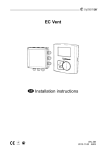
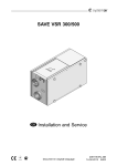
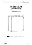
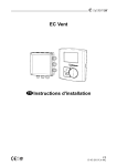
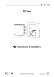
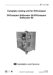
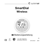
SmartDial
Wireless
User Manual
Document in original
language
-en_GB
08-07-2014
A003
Contents
1 Declaration of Conformity ............................... 1
2 Product description ...................................... 3
3 Guidelines for installation ............................... 3
4 Operation.................................................. 4
5 Interface Description ..................................... 5
5.1 Display symbols .................................. 7
5.2 Power-up screen.................................. 13
5.3 Binding screen .................................... 15
5.4 Default screen..................................... 17
5.5 Setting Temperature and Fan speed ........... 19
6 Change batteries ......................................... 22
7 Troubleshooting .......................................... 23
1 Declaration of Conformity
Manufacturer
Systemair AB
Industrivägen 3
SE-739 30 Skinnskatteberg SWEDEN
Office: +46 222 440 00 Fax: +46 222 440 99
www.systemair.com
hereby confirms that SmartDial, CO2 sensor, Humidity
sensor, Input module and RS485 Gateway comply with all
applicable requirements in the Directive 1999/5/EC.
EN 61000-6-3 2007:
Emission standard, residential, commercial and light industry.
EN 61000-6-1 2007:
Immunity standard, residential, commercial and light industry.
ETSI EN 300 220-1:
Electromagnetic compatibility and Radio spectrum Matters
(ERM); Short Range Devices (SRD); Radio equipment to be
used in the 25 MHz to 1000 MHz frequency range with power
levels ranging up to 500 mW; Part 1: Technical characteristics
and test methods 1.1 Safety Requirements and Codes
SmartDial
User Manual
1
Systemair AB
EN 60730-1: 2007:
Safety requirements for automatic controls in household and
similar use.
The units will meet the requirements of the WEEE and ROHS
directives.
The complete technical documentation is available.
Skinnskatteberg, 02-07-2014
Mats Sándor
Technical Director
SmartDial
User Manual
2
Systemair AB
2 Product description
SmartDial makes it possible to wirelessly set the temperature
and fan speed on the Systemair air handling unit. It is also
possible to see alarms reported by the air handling unit.
SmartDial, together with up to nine other wireless modules are
wirelessly connected to a gateway. The gateway is physically
connected to the air handling unit with a cable.
Note:
A standard control panel can be simultaneously connected,
see the RS485 Gateway User Manual chapter Connections
for more information.
SmartDial is intended for wall mounting either on the wall or
on a wall-box.
SmartDial is powered by 2 Alkaline AA-Batteries, included.
Expected battery lifetime is 2 years.
3 Guidelines for installation
See the RS485 Gateway User Manual for more information.
SmartDial
User Manual
3
Systemair AB
4 Operation
The Systemair air handling unit can operate in one of the
following 5 modes:
Mode
Function
OFF
The fans in the air handling unit are stopped.
Away
Low energy support control is activated.
Auto
The fans are working according to values preset in the air
handling unit.
Party
The fans are running at a specified speed and time preset in
the menu "Ext/Force run" in the air handling unit.
Manual
The fan speed is controlled manually and is either off, low,
normal or high
SmartDial
User Manual
4
Systemair AB
5 Interface Description
1
3
2
4
5
6
Fig. 1 Interface description
SmartDial
User Manual
5
Systemair AB
Position
Description
Explanation
1
Display
Shows symbols, menus and settings.
2
Dial
Move through and change fan speed
settings and temperature settings
by turning the dial clockwise or
counterclockwise.
3
Cancel button
Cancel menu choices or settings by
pressing the button.
Step back in the menu levels out to the
starting point.
4
Party mode
button
Activates DI5 in the main controller in
the air handling unit (Extended/Forced
running). The corresponding icon at
the top of the display is visible when
active.
To adjust the fan speed, see the unit’s
panel and follow it’s instructions.
SmartDial
User Manual
6
Systemair AB
Position
Description
Explanation
5
Home/away
button
Activates DI7 in the main controller
in the air handling unit. The
corresponding icon at the top of the
display is visible when active.
6
Confirm button
Confirm menu choices or settings by
pressing the button.
5.1 Display symbols
Symbol
Description
Explanation
Temp
Shows the currently set temperature.
Confirm the setting with the “confirm
button”.
Alarm
Visible if the air handling unit reports
an alarm, if there is an error in the
appliance or if the bind procedure is
not successful.
SmartDial
User Manual
7
Systemair AB
Symbol
Description
Explanation
Battery
The battery symbol is visible if battery
level is low, not visible otherwise.
Broken sensor
or short circuit.
Invalid temperature value transmitted.
SmartDial
User Manual
8
Systemair AB
Symbol
A
C
B
D
Description
Explanation
Fan speed
Shows the current fan speed. The fan
speed can be set manually in 4 steps:
Off, Low, Norm and High by turning
the dial and confirm with the confirm
button after completed setting.
A. Fan stopped. The fan can be set
to OFF by activating MAN fan stop.
See the air handling unit service
menu description under functions.
B. Low fan speed: Can be used when
leaving the building for a longer
period.
C. Normal fan speed: Will give
required air change under normal
conditions.
D. High fan speed: To increase the
airflow if necessary.
SmartDial
User Manual
9
Systemair AB
Symbol
Description
Explanation
Auto mode
The
icon is shown when the
system is in auto mode.
Auto mode must be manually chosen
if a wireless Humidity or CO2 sensor is
connected
AUTO and the actual fan speed is
shown when a wireless Humidity or
CO2 sensor is activated.
When setting fan speed, auto appears
when turning the dial one more step
clockwise when the fan symbol is
already filled. Fan speed symbol D.
Wireless Communication
Fault
The Wireless Communication Fault
symbol is visible if the communication
with the gateway is lost, not visible
otherwise (Communication lost for
more than 60 minutes).
SmartDial
User Manual
10
Systemair AB
Symbol
Description
Explanation
Home/away
function
When this symbol appears, low
energy support control is active. Heat
exchanger operating by the adjusted
setpoint value and a active re-heater
has support control for lowest setpoint.
(12 C°) .
When the away mode is not active
and the away button is pressed, this
new mode request is sent to the main
controller in the air handling unit. The
button does not handle new requests
until the (new) mode is received from
the main controller in the air handling
unit.
The icon is flashing when the mode is
changed and the new mode is not yet
confirmed by the main controller in the
air handling unit.
SmartDial
User Manual
11
Systemair AB
Symbol
Description
Explanation
Party mode
function
When this symbol appears,
extended/forced running function
is active.
When the party mode is not active
and the party button is pressed, this
new mode request is sent to the main
controller in the air handling unit. The
button does not handle new requests
until the (new) mode is received from
the main controller in the air handling
unit.
The icon is flashing when the mode is
changed and the new mode is not yet
confirmed by the main controller in the
air handling unit.
Cancel
Cancel symbol
Confirm
Confirm symbol
SmartDial
User Manual
12
Systemair AB
Warning
It is not recommended to activate MAN fan stop (set fan to
OFF) in standard households.
If MAN fan stop is activated, the unit should be provided
with dampers in outdoor and exhaust air ducts to avoid cold
draught and risk of condensation when the unit has been
stopped.
5.2 Power-up screen
After power-up, all icons will be lit for two seconds.
Fig. 2 Power-up screen
SmartDial
User Manual
13
Systemair AB
After two seconds the software version will be shown.
If SmartDial is not bound to the gateway after 4 seconds, the
binding screen (figure 3) will be shown.
If SmartDial is bound to the gateway after 4 seconds, the
default screen (figure 4) will be shown.
SmartDial
User Manual
14
Systemair AB
5.3 Binding screen
Fig. 3 Binding screen
If SmartDial is not bound to the gateway after 4 seconds, the
binding screen (figure 3) will be shown.
In binding mode, SmartDial contacts the gateway and
requests connection.
Note:
Binding mode must first be activated on the gateway. See
RS485 Gateway User Manual for more information.
The text bnd is shown, the OK icon
SmartDial
is visible.
User Manual
15
Systemair AB
The “Cancel” icon is visible when SmartDial is already
bound.
To initiate the bind procedure, press the confirm button (6).
When the bind is successful the default screen (figure 4) is
shown.
The Cancel button (3) is only active when SmartDial is already
bound. When active and pressed the default screen (figure
4) is shown.
Note:
There are no special actions taken when the cancel button (3)
is pressed, existing binding is not deleted.
When SmartDial is bound and after 30 seconds without user
interaction, the default screen (figure 4) is shown.
SmartDial
User Manual
16
Systemair AB
5.4 Default screen
Fig. 4 Default screen
The 2 middle button icons
and
are visible.
The actual room temperature is shown with a resolution of
0.5 °C.
In the rare case that the temperature cannot be measured
are shown.
(product failure), two dashes
The actual fan speed is always shown.
The 4 icons above the buttons are visible.
icon is shown if the system is in auto mode.
The
SmartDial
User Manual
17
Systemair AB
When the dial is turned, either the square around the supply
air temperature or fan speed is flashing to indicate that a
change of the setpoint can be performed by pressing the
confirm (6) button.
When the cancel (3) and confirm (6) button are pressed at the
same time for 10 seconds, the binding screen is shown.
Note:
Normally the binding screen is automatically shown after initial
power-up. So this is only needed in rare cases where you
want to connect the device to another system.
SmartDial
User Manual
18
Systemair AB
5.5 Setting Temperature and Fan speed
SmartDial
User Manual
19
Systemair AB
Position
Description
Explanation
1
Dial
Move through and change fan
speed settings and temperature
settings by turning the dial
clockwise or counterclockwise.
2
Square
The square is moving in the
settings by turning the dial
clockwise or counterclockwise.
When turning the dial, the square appears and you can
choose either fan speed settings or temperature settings.
SmartDial
User Manual
20
Systemair AB
1
3
2
4
5
6
Press the conform button (6) to change fan or temperature
settings, then the setting can be changed by turning the dial.
When the desired value is shown, press the confirm button (6)
to accept the value. Press the cancel button (3) to back out
to the starting point (no square active) at any time. If there
is no activity for 30 seconds it will automatically back out to
the starting point.
SmartDial
User Manual
21
Systemair AB
6 Change batteries
1. Put a screwdriver or similar
between the wall and the dial (1)
and flip out the dial.
1
2
2. Use a screwdriver or similar to
push down the lock (2) and flip
out the unit (3).
3
3. Change the batteries.
4. Remount in opposite order.
SmartDial
User Manual
22
Systemair AB
7 Troubleshooting
Indication
Probable cause and action
SmartDial is not working
Check if batteries are depleted
or inserted incorrectly
RF binding and/or
communication problems
Check if remote modules too
close (< 1 m) or too far away (>
30 m) from the gateway
SmartDial
User Manual
23
Systemair AB
lastpage
Systemair AB reserves the right to make changes and improvements
to the contents of this manual without prior notice.
Systemair AB
Industrivägen 3
SE-739 30 Skinnskatteberg, Sweden
Phone +46 222 440 00
Fax +46 222 440 99
www.systemair.com