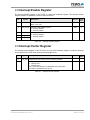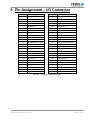
1
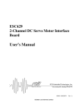
The Embedded I/O Company TIP120 Motion Controller with Incremental Encoder Interface Version 1.0 User Manual Issue 1.0.5 August 2014 TEWS TECHNOLOGIES GmbH Am Bahnhof 7 25469 Halstenbek, Germany www.tews.com Phone: +49-(0)4101-4058-0 Fax: +49-(0)4101-4058-19 e-mail: [email protected] TIP120-10 2 axes motion controller using LM628 with incremental encoder interface TIP120-11 1 axis motion controller using LM628 with incremental encoder interface TIP120-20 2 axes motion controller using LM629 with incremental encoder interface TIP120-21 This document contains information, which is proprietary to TEWS TECHNOLOGIES GmbH. Any reproduction without written permission is forbidden. TEWS TECHNOLOGIES GmbH has made any effort to ensure that this manual is accurate and complete. However TEWS TECHNOLOGIES GmbH reserves the right to change the product described in this document at any time without notice. TEWS TECHNOLOGIES GmbH is not liable for any damage arising out of the application or use of the device described herein. 1 axis motion controller using LM629 with incremental encoder interface Style Conventions TIP120-30 Hexadecimal characters are specified with prefix 0x, i.e. 0x029E (that means hexadecimal value 029E). 2 axes motion controller using LM628 and LM629 with incremental encoder interface For signals on hardware products, an ‚Active Low’ is represented by the signal name with # following, i.e. IP_RESET#. Access terms are described as: W Write Only R Read Only R/W Read/Write R/C Read/Clear R/S Read/Set 2014 by TEWS TECHNOLOGIES GmbH All trademarks mentioned are property of their respective owners. TIP120 User Manual Issue 1.0.5 Page 2 of 14 Issue Description Date 1.0 First Issue November 1999 1.1 General Revision July 2003 1.2 Update in Programming Hints Section May 2004 1.3 New address TEWS LLC September 2006 1.0.4 New Notation for User Manual and Engineering Documentation May 2009 1.0.5 General Revision August 2014 TIP120 User Manual Issue 1.0.5 Page 3 of 14 Table of Contents 1 2 3 4 PRODUCT DESCRIPTION ......................................................................................... 6 TECHNICAL SPECIFICATION ................................................................................... 7 ID PROM CONTENTS ................................................................................................ 8 IP ADDRESSING ........................................................................................................ 9 4.1 4.2 4.3 4.4 4.5 4.6 4.7 4.8 4.9 5 6 I/O Addressing................................................................................................................................. 9 Control / Status Register .............................................................................................................. 10 Data Register ................................................................................................................................. 10 Output Register ............................................................................................................................. 10 Input Register ................................................................................................................................ 10 Interrupt Status Register .............................................................................................................. 10 Interrupt Control Register ............................................................................................................ 11 Interrupt Enable Register ............................................................................................................. 12 Interrupt Vector Register .............................................................................................................. 12 PROGRAMMING HINTS .......................................................................................... 13 PIN ASSIGNMENT – I/O CONNECTOR .................................................................. 14 TIP120 User Manual Issue 1.0.5 Page 4 of 14 List of Figures FIGURE 1-1 : BLOCK DIAGRAM ...................................................................................................................... 6 List of Tables TABLE 2-1 : TECHNICAL SPECIFICATION ..................................................................................................... 7 TABLE 3-1 : ID PROM CONTENTS.................................................................................................................. 8 TABLE 4-1 : REGISTER SET............................................................................................................................ 9 TABLE 4-2 : OUTPUT REGISTER .................................................................................................................. 10 TABLE 4-3 : INPUT REGISTER ...................................................................................................................... 10 TABLE 4-4 : INTERRUPT STATUS REGISTER............................................................................................. 11 TABLE 4-5 : INTERRUPT CONTROL REGISTER ......................................................................................... 11 TABLE 4-6 : INTERRUPT ENABLE REGISTER............................................................................................. 12 TABLE 4-7 : INTERRUPT VECTOR REGISTER ............................................................................................ 12 TABLE 6-1 : PIN ASSIGNMENT I/O CONNECTOR ....................................................................................... 14 TIP120 User Manual Issue 1.0.5 Page 5 of 14 1 Product Description The TIP120 family of IndustryPack compatible modules is designed for motion control applications using incremental encoders as position feedback. There are five board options available: The TIP120-1x is a one or two axes motion control IP based on the LM628 controller from National Semiconductor providing a ±10V output signal by a 12 bit D/A converter. The ±10V output signal is buffered by an operational amplifier which is able to drive unlimited capacitive loads. This signal can be used to drive the power amplifier of the motor drive system. The TIP120-2x is a one or two axes motion control IP based on the LM629 controller from National Semiconductor providing an 8 bit sign-magnitude PWM output signal. The PWM output signal is buffered by a TTL driver capable up to +/- 24mA. This signal can be used for directly driving H switches. The TIP120-30 is a two axes motion control IP based on the LM628 controller from National Semiconductor for axis 1 providing a ±10V output signal by a 12 bit D/A converter and based on the LM629 controller from National Semiconductor for axis 2 offering an 8 bit sign / magnitude PWM output signal. The +/-10V output signal is buffered by an operational amplifier which is able to drive unlimited capacity loads. This signal can be used to drive the power amplifier of the motor drive system. The PWM output is buffered by a TTL driver capable up to +/-24mA. This signal can be used for directly driving H switches. The position feedback is provided by an incremental encoder interface. The level of the encoder signals can be TTL or RS422. The LM628 / LM629 used on the TIP120-xx are dedicated motion control processors designed for use with a variety of DC and brushless DC servo motors, and other servomechanisms which provide a quadrature (quadruple) incremental position feedback signal. The LM628 / LM629 perform the intensive, real-time computational tasks required for high performance digital motion control. The host control software interface is facilitated by a high-level command set. Three isolated 24V DC digital inputs are available for user functionality. The function for the three inputs may be limit switches and emergency stop input. A floating optical output can be controlled by software, for example as enable signal for the motor power amplifier. Figure 1-1 : Block Diagram TIP120 User Manual Issue 1.0.5 Page 6 of 14 2 Technical Specification IP Interface Interface Single Size IndustryPack Logic Interface compliant to ANSI/VITA 4-1995 ID ROM Data Format I I/O Space Used (LM62x Registers, Interrupt Vector Register) Memory Space Not Used Interrupts Int1 used (LM62x Axis 1) / Int2 used (LM62x Axis 2) DMA Not supported Clock Rate 8 MHz Module Type Type I Wait states LM62x Registers: Read cycle 1 wait state, write cycle no wait states All others: no wait states Interrupt Vectored interrupts On Board Devices Motion Controller National LM628 for +/-10V output signal: D/A converter: 12 bit DAC, +/-10V output Output OP: +/-10V at +/-10mA, unlimited capacitive load National LM629 for PWM output signal (TTL): 8 bit sign-magnitude PWM, TTL signal +/-24mA I/O Interface Optical Isolated I/O Three 24V DC inputs, protected against confusing the pole for each axis, input threshold 8.5V to 14V. One software controlled floating output for each axis (transistor of optocoupler). Encoder Input Quadrature encoder interface for RS422 or TTL level with phase A, phase B and index Minimum pulse width (high and low) : 2µs Interface Connector 50-conductor flat cable Physical Data Power Requirements 200mA typical @ +5V DC 40mA typical @ +12V DC 40mA typical @ -12V DC Temperature Range Operating Storage MTBF TIP120-10: 285000 h 0 °C to +70 °C -25°C to +125°C MTBF values shown are based on calculation according to MIL-HDBK-217F and MIL-HDBK-217F Notice 2; Environment: GB 20°C. The MTBF calculation is based on component FIT rates provided by the component suppliers. If FIT rates are not available, MIL-HDBK-217F and MIL-HDBK-217F Notice 2 formulas are used for FIT rate calculation. Humidity 5 – 95 % non-condensing Table 2-1 : Technical Specification TIP120 User Manual Issue 1.0.5 Page 7 of 14 3 ID Prom Contents Offset Function Value 0x01 ASCII ‘I’ 0x49 0x03 ASCII ‘P’ 0x50 0x05 ASCII ‘A’ 0x41 0x07 ASCII ‘C’ 0x43 0x09 Manufacturer ID 0xB3 0x0B Model Number 0x1E 0x0D Revision 0x10 0x0F Reserved 0x00 0x11 Driver-ID Low - Byte 0x00 0x13 Driver-ID High - Byte 0x00 0x15 Number of bytes used 0x0D CRC TIP120-10: 0x72 TIP120-11: 0x53 TIP120-20: 0x8D TIP120-21: 0xAC TIP120-30: 0xC7 0x19 Board Option TIP120-10: 0x0A TIP120-11: 0x0B TIP120-20: 0x14 TIP120-21: 0x15 TIP120-30: 0x1E … Not used … 0x3F - 0x00 0x17 Table 3-1 : ID PROM Contents TIP120 User Manual Issue 1.0.5 Page 8 of 14 4 IP Addressing 4.1 I/O Addressing The complete register set of the TIP120 accessible in the IP I/O space. Offset Symbol Description Size (Bit) Axis 1 Registers 0x01 CONTROL1/STATUS1 Control/Status Register LM628/LM629 8 0x03 DATA1 Data Register LM628/LM629 8 0x05 OUTPUT1 Output Register Control Switch 8 0x07 INPUT1 Input Register Control Switches 8 0x09 INTSTAT1 Interrupt Status Register 8 0x0B INTCR1 Interrupt Control Register 8 0x0D INTENA1 Interrupt Enable Register 8 0x0F Reserved Axis 2 Registers 0x11 CONTROL2/STATUS2 Control/Status Register LM628/LM629 8 0x13 DATA2 Data Register LM628/LM629 8 0x15 OUTPUT2 Output Register Control Switch 8 0x17 INPUT2 Input Register Control Switches 8 0x19 INTSTAT2 Interrupt Status Register 8 0x1B INTCR2 Interrupt Control Register 8 0x1D INTENA2 Interrupt Enable Register 8 0x1F Reserved 0x21 INTVEC Interrupt Vector Register 8 Table 4-1 : Register Set TIP120 User Manual Issue 1.0.5 Page 9 of 14 4.2 Control / Status Register The Control Register of the TIP120 is a byte wide write only register. An access to the Control Register will select the next command to the motion controller. For further information about the command settings of the motion controller please refer to the LM628 / LM629 data sheet. The Status Register of the TIP120 is a byte wide read only register. 4.3 Data Register The Data Register of the TIP120 is a byte wide read/write register. An access to the Data Register requires an access to the Control Register first. The motion controller uses a multiplexed 8 bit asynchronous host interface. A 16 bit data read/write to the motion controller requires two 8 bit accesses. The first access takes the high byte and the second access the low byte of the 16 bit word. For further information about the data settings of the motion controller please refer to LM628 / LM629 data sheet. 4.4 Output Register The Output Register of the TIP120 is a byte wide read/write register. The Output Register controls an optical isolated open collector output / floating switch. The output switch may be used for an additional axis enable control. Bit Symbol 7:1 0 Description Access Reset Value R/W 0 Read as ‘0’ Write : Don’t care OUT1 OUTPUT1 Control Axis X 0 : Open Collector Output Driver OFF / Floating Switch Open 1 : Open Collector Output Driver ON / Floating Switch Closed Table 4-2 : Output Register 4.5 Input Register The Input Register of the TIP120 is a byte wide read register. The Input Register shows the actual level at the TIP120 input pins. The inputs may be used for limit switches and emergency stop detection for each axis. Bit Symbol 7:3 Description Access Reset Value Read as ‘0’ 2 IN3 1 IN2 0 IN1 INPUT 1-3 Status of Axis X 0 : Input x not active 1 : Input x active R Table 4-3 : Input Register 4.6 Interrupt Status Register The Interrupt Status Register of the TIP120 is a byte wide mixed access register. The Interrupt Status Register reflects the interrupt status of the three TIP120 inputs and the TIP120 LM62x motion TIP120 User Manual Issue 1.0.5 Page 10 of 14 controller interrupt. If an interrupt is pending, the corresponding Interrupt Status Register bit is read as ‘1’. To quit the interrupts for the TIP120 inputs, write a ‘1’ to the corresponding bit of the Interrupt Status Register. The LM62x motion controller interrupts must be acknowledged by programming the LM62x. Bit Symbol 7:4 Description Access Reset Value Read as ‘0’ Write : Don’t care 3 INT_LM Interrupt LM62x of Axis X 0 : No active interrupt 1 : Active interrupt 2 INT_IN3 1 INT_IN2 0 INT_IN1 Interrupt INPUT 1-3 of Axis X 0 : No active interrupt 1 : Active interrupt Write ‘1’ to clear interrupt. R R/C Table 4-4 : Interrupt Status Register The input interrupts are only active if the corresponding enable bit in the Interrupt Enable Register is set to ‘1’. The interrupt status of the LM62x can be read at any time. NOTE : After RESET# a LM62x interrupt is pending !!! The user must execute the LM62x ‘Reset Interrupt’ routine. 4.7 Interrupt Control Register The Interrupt Control Register of the TIP120 is a byte wide read/write register. The Interrupt Control Register controls which signal transition forces an interrupt for the TIP120 inputs. Bit Symbol 7:3 Description Access Reset Value R/W 000 Read as ‘0’ 2 INT_IN3_POL 1 INT_IN2_POL 0 INT_IN1_POL Transition Select INPUT 1-3 of Axis X 0 : Interrupt Request on High to Low Transition 1 : Interrupt Request on Low to High Transition Table 4-5 : Interrupt Control Register TIP120 User Manual Issue 1.0.5 Page 11 of 14 4.8 Interrupt Enable Register The Interrupt Enable Register of the TIP120 is a byte wide read/write register. The Interrupt Enable Register enables or disables the various interrupt sources. Bit Symbol Description 7:4 Access Reset Value Read as ‘0’ Write : Don’t care 3 INT_LM_EN Interrupt Enable LM62x of Axis X 0 : Interrupt disabled 1 : Interrupt enabled R/W 0 2 INT_IN3_EN 000 INT_IN2_EN 0 INT_IN1_EN Interrupt Enable INPUT1-3 of Axis x 0 : Interrupt disabled 1 : Interrupt enabled R/W 1 Table 4-6 : Interrupt Enable Register 4.9 Interrupt Vector Register The Interrupt Vector Register of the TIP120-xx is a byte wide read/write register. It holds the interrupt vector passed to the CPU during interrupt acknowledge cycles. Bit Symbol 7:1 INT_VEC 0 Description Access Reset Value Higher bits of 8 bit Interrupt Vector, loaded by software. Bit is generated by the TIP120 hardware. 0 : Interrupt Axis 1 1 : Interrupt Axis 2 Axis 1 generates interrupts on INTREQ0#, Axis 2 generates interrupts on INTREQ1# of the IP bus. R/W Table 4-7 : Interrupt Vector Register TIP120 User Manual Issue 1.0.5 Page 12 of 14 5 Programming Hints The LM628 Motion Controller can operate in an 8 bit DAC mode or in a 12bit DAC mode. The LM628 default mode after power-up or reset is the 8 bit DAC mode. The TIP120 does only support the 12 bit DAC mode. For board options with the LM628 Motion Controller, the user must issue the PORT12 command early in the initialization phase to set the LM628 DAC mode to 12 bit. Please see the LM628 documentation for details. TIP120 User Manual Issue 1.0.5 Page 13 of 14 6 Pin Assignment – I/O Connector Pin Function Pin Level 1 INPUT1 Axis 1 + 26 INPUT1 Axis 2 + 2 INPUT1 Axis 1 - 27 INPUT1 Axis 2 - 3 INPUT2 Axis 1 + 28 INPUT2 Axis 2 + 4 INPUT2 Axis 1 - 29 INPUT2 Axis 2 - 5 INPUT3 Axis 1 + 30 INPUT3 Axis 2 + 6 INPUT3 Axis 1 - 31 INPUT3 Axis 2 - 7 OUPUT1 Axis 1+ 32 OUPUT1 Axis 2+ 8 OUPUT1 Axis 1 - 33 OUPUT1 Axis 2 - 9 NC 34 NC 10 NC 35 NC 11 AGND 36 AGND 12 PWM Output Axis 1 MAG 37 PWM Output Axis 2 MAG 13 PWM Output Axis 1 SIGN 38 PWM Output Axis 2 SIGN 14 DAC Output Axis 1 39 DAC Output Axis 2 15 DAC GND Axis 1 40 DAC GND Axis 2 16 AGND 41 AGND 17 Phase A Axis 1 42 Phase A Axis 2 18 Phase A Axis 1# 43 Phase A Axis 2# 19 Phase B Axis 1 44 Phase B Axis 2 20 Phase B Axis 1# 45 Phase B Axis 2# 21 Phase Index Axis 1 46 Phase Index Axis 2 22 Phase Index Axis 1# 47 Phase Index Axis 2# 23 AGND 48 AGND 24 NC 49 NC 25 NC 50 NC Table 6-1 : Pin Assignment I/O Connector TIP120 User Manual Issue 1.0.5 Page 14 of 14