1
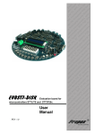
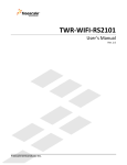
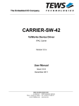
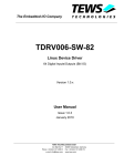
The Embedded I/O Company TIP115 5 Channel SSI Interface with ‘Listen Only’ Mode Version 1.0 User Manual Issue 1.1 September 2004 D75115800 TEWS TECHNOLOGIES GmbH Am Bahnhof 7 Phone: +49-(0)4101-4058-0 e-mail: [email protected] 25469 Halstenbek / Germany Fax: +49-(0)4101-4058-19 www.tews.com TEWS TECHNOLOGIES LLC 1 E. Liberty Street, Sixth Floor Phone: +1 (775) 686 6077 e-mail: [email protected] Reno, Nevada 89504 / USA Fax: +1 (775) 686 6024 www.tews.com TIP115-10 5 Channel SSI Interface with ‘Listen Only’ Mode This document contains information, which is proprietary to TEWS TECHNOLOGIES GmbH. Any reproduction without written permission is forbidden. TEWS TECHNOLOGIES GmbH has made any effort to ensure that this manual is accurate and complete. However TEWS TECHNOLOGIES GmbH reserves the right to change the product described in this document at any time without notice. TEWS TECHNOLOGIES GmbH is not liable for any damage arising out of the application or use of the device described herein. Style Conventions Hexadecimal characters are specified with prefix 0x, i.e. 0x029E (that means hexadecimal value 029E). For signals on hardware products, an ‚Active Low’ is represented by the signal name with # following, i.e. IP_RESET#. Access terms are described as: W Write Only R Read Only R/W Read/Write R/C Read/Clear R/S Read/Set 1998-2004 by TEWS TECHNOLOGIES GmbH IndustryPack is a registered trademark of SBS Technologies, Inc Issue Description Date 1.0 First Issue May 2004 1.1 Change of Control Register description September 2004 TIP115 User Manual Issue 1.0 Page 2 of 17 Table of Contents 1 2 3 4 PRODUCT DESCRIPTION ......................................................................................... 5 TECHNICAL SPECIFICATION................................................................................... 6 ID PROM CONTENTS ................................................................................................ 7 IP ADDRESSING........................................................................................................ 8 4.1 4.2 4.3 4.4 4.5 4.6 4.7 4.8 4.9 4.10 4.11 5 OPERATION MODES............................................................................................... 14 5.1 5.2 5.3 6 I/O Addressing ...........................................................................................................................8 Control Register.........................................................................................................................9 Data Word Low Register .........................................................................................................10 Data Word High Register.........................................................................................................10 Ready Status Register.............................................................................................................10 Parity Error Status Register....................................................................................................11 Read Error Status Register .....................................................................................................11 Interrupt Status Register.........................................................................................................12 Interrupt Enable Register ........................................................................................................12 Interrupt Vector Register.........................................................................................................12 Start Convert CH0-CH4 Register ............................................................................................13 Standard SSI Interface Controller ..........................................................................................14 ‘Listen only’ Mode....................................................................................................................15 Mode behavior differences .....................................................................................................16 PIN ASSIGNMENT – I/O CONNECTOR .................................................................. 17 TIP115 User Manual Issue 1.0 Page 3 of 17 Table of Figures FIGURE 1-1 : BLOCK DIAGRAM.......................................................................................................................5 FIGURE 2-1 : TECHNICAL SPECIFICATION....................................................................................................6 FIGURE 3-1 : ID PROM CONTENTS ................................................................................................................7 FIGURE 4-1 : TIP115 REGISTER SET..............................................................................................................8 FIGURE 4-2 : CONTROL REGISTER................................................................................................................9 FIGURE 4-3 : READY STATUS REGISTER....................................................................................................10 FIGURE 4-4 : PARITY ERROR STATUS REGISTER.....................................................................................11 FIGURE 4-5 : READ ERROR STATUS REGISTER........................................................................................11 FIGURE 4-6 : INTERRUPT STATUS REGISTER ...........................................................................................12 FIGURE 4-7 : INTERRUPT ENABLE REGISTER ...........................................................................................12 FIGURE 5-1 : WIRING EXAMPLE: CHANNEL 0, SSI INTERFACE CONTROLLER MODE..........................14 FIGURE 5-2 : WIRING EXAMPLE: CHANNEL 0, ‘LISTEN ONLY’ MODE......................................................15 FIGURE 5-3 : MODE BEHAVIOR DIFFERENCES..........................................................................................16 FIGURE 6-1 : PIN ASSIGNMENT I/O CONNECTOR......................................................................................17 TIP115 User Manual Issue 1.0 Page 4 of 17 1 Product Description The TIP115 is an IndustryPack compatible module for motion control applications. The TIP115 offers five independent channels. Each of these channels can be operated as a standard SSI interface controller or in a ‘Listen only’ Mode. The standard SSI interface controller outputs a clock burst to the absolute encoder and receives the returned positional data. The SSI interface controller operates with a programmable clock rate from 1µs to 15µs and programmable data word length from 1 bit to 32 bit. In ‘Listen only’ Mode the channel listens to an existing SSI interface to observe its data transfer. It takes both the SSI clock and data as inputs. In ‘Listen only’ Mode the channel also has a programmable data word length from 1 bit to 32 bit; the SSI clock rate of the observed SSI interface can be in the range of 1µs to 15µs. In both modes the data word can be encoded in binary- or in Gray code and with odd, even or no parity. The data inputs are galvanically isolated by high speed optocouplers. The level of the input and output signals is RS422. The data inputs are galvanically isolated by high speed optocouplers. The level of the input and output signals is RS422. Figure 1-1 : Block Diagram TIP115 User Manual Issue 1.0 Page 5 of 17 2 Technical Specification IP Interface Interface Single Size IndustryPack Logic Interface compliant to ANSI/VITA 4-1995 ID ROM Data Format I I/O Space Used with no wait states Memory Space Not used Interrupts Only INTREQ0# is used DMA Not supported Clock Rate 8 MHz Module Type Type I SSI Interface 5 independent channels SSI CLK Output Differential driver (RS422) SSI Data Input Optically isolated differential input SSI Clock Rate 1µs to 15µs SSI Data word length Programmable from 1 bit to 32 bit Interrupts IP interrupt 0 for all 5 SSI channels; 2 registers and one Interrupt Vector for individual interrupt handling Interface Connector 50-conductor flat cable Power Requirements 70mA typical @ +5V DC, no load Physical Data Temperature Range Operating Storage 0 °C to +70 °C -45°C to +125°C MTBF 331000 h Humidity 5 – 95 % non-condensing Weight 32 g Figure 2-1 : Technical Specification TIP115 User Manual Issue 1.0 Page 6 of 17 3 ID PROM Contents Address Function Contents 0x01 ASCII ‘I’ 0x49 0x03 ASCII ‘P’ 0x50 0x05 ASCII ‘A’ 0x41 0x07 ASCII ‘C’ 0x43 0x09 Manufacturer ID 0xB3 0x0B Model Number 0x3A 0x0D Revision 0x10 0x0F Reserved 0x00 0x11 Driver-ID Low - Byte 0x00 0x13 Driver-ID High - Byte 0x00 0x15 Number of bytes used 0x0D 0x17 CRC 0x77 0x19 Version -10 0x0A Figure 3-1 : ID PROM Contents TIP115 User Manual Issue 1.0 Page 7 of 17 4 IP Addressing 4.1 I/O Addressing The complete register set of the TIP115 is accessible in the I/O space of the IP. Address Symbol Description Size (Bit) Access 0x00 CONT0 Control Register Channel 0 16 R/W 0x02 DATAL0 Data Word Low Register Channel 0 16 R/W 0x04 DATAH0 Data Word High Register Channel 0 16 R 0x06 CONT1 Control Register Channel 1 16 R/W 0x08 DATAL1 Data Word Low Register Channel 1 16 R/W 0x0A DATAH1 Data Word High Register Channel 1 16 R 0x0C CONT2 Control Register Channel 2 16 R/W 0x0E DATAL2 Data Word Low Register Channel 2 16 R/W 0x10 DATAH2 Data Word High Register Channel 2 16 R 0x12 CONT3 Control Register Channel 3 16 R/W 0x14 DATAL3 Data Word Low Register Channel 3 16 R/W 0x16 DATAH3 Data Word High Register Channel 3 16 R 0x18 CONT4 Control Register Channel 4 16 R/W 0x1A DATAL4 Data Word Low Register Channel 4 16 R/W 0x1C DATAH4 Data Word High Register Channel 4 16 R 0x21 READY Data Ready Status Register 8 R 0x23 PAR_ERR Parity Error Status Register 8 R 0x25 RD_ERR Read Error Status Register 8 R 0x27 INTSTAT Interrupt Status Register 8 R/W 0x29 INTENA Interrupt Enable Register 8 R/W 0x2B INTVEC Interrupt Vector Register 8 R/W 0x2D CONVERT Start Convert CH0-CH4 Register 8 W Figure 4-1 : TIP115 Register Set TIP115 User Manual Issue 1.0 Page 8 of 17 4.2 Control Register The Control Register is used to program the operation mode, clock speed (Standard SSI Interface Controller only), parity, the data encoding of the SSI encoder and the number of data bits coming from the serial absolute encoder. Each of the five SSI interfaces can be configured independently of the other by the corresponding Control Register. This register is cleared automatically with the IP_RESET signal. Bit Symbol 15 Description Access Reset Value Unused, always reads as ‘0’ 14 Mode 1 = ‘Listen only’ Mode 0 = Standard SSI Interface Controller R/W 0 13 BC5 R/W 0 12 BC4 11 BC3 10 BC2 9 BC1 8 BC0 Number of Data Bits Bits are used to program the number of bits of the serial absolute encoder. It can be read and written by software. The data bits can be programmed in the range from 1 to 32. BC5…BC0 = 0x01 to 0x20 means 1 to 32 bit. BC5…BC0 = 0x00 not used BC5…BC0 = 0x21 to 0x3F not used 7 Coding Data word coding 1 = Gray Code The data word is converted into binary code 0 = Binary Code R/W 0 6 Zero Bit Parity Bit with Zero Bit, controls the clock cycles 1 = two additional clock cycles 0 = one additional clock cycle are provided to get the parity bit R/W 0 5 Even / Odd Controls the parity detection 1 = odd parity 0 = even parity This bit is only useful if bit 4 is set to ‘1’. R/W 0 4 Parity Encoder with parity - If encoder provides a parity bit: 1 = detect parity errors R/W 0 3 CR3 R/W 0 2 CR2 1 CR1 0 CR0 Clock Rate for encoder serial clock speed The clock can be programmed in steps of 1µs in the range of 1 to 15. A value of 0 for the clock rate will stop the operation of the SSI interface. The ‘Listen only’ Mode will ignore the Clock Rate setting; in this mode the Clock Rate will be detected automatically. Figure 4-2 : Control Register Note that a value of 0x00 for BC5...BC0 is not used and will result an invalid SSI Data. A value from 0x21 to 0x3F will also result an invalid SSI Data because of the limited 32 bit input shift register of the TIP115. TIP115 User Manual Issue 1.0 Page 9 of 17 4.3 Data Word Low Register The serial data of the encoder is shifted into the word wide registers Data Word Low and Data Word High. The Data Word Low Register holds the least significant word of the 32 bit shift register. In Standard SSI Interface Controller a write access to the Data Word Low Register Channel X initiates a data transfer from the encoder independently of the other channels. This register is cleared automatically with the IP_RESET signal. The data register may not contain valid data if the serial data transfer is in progress (the corresponding ready bit is read as ‘0’). 4.4 Data Word High Register The serial data of the encoder is shifted into the word wide registers Data Word Low and Data Word High. The Data Word High Register holds the most significant word of the 32 bit shift register. This register is cleared automatically with the IP_RESET signal. The data register may not contain valid data if the serial data transfer is in progress (the corresponding ready bit is read as ‘0’). 4.5 Ready Status Register The Ready Status Register is a byte wide read only register. This register indicates that the data transfer between the encoder is completed and the position data can be read. When the position data was read, the Ready Status Bit is reset to ‘0’. The Ready Status Bit is set after every data transmission, even if a parity or a read error was issued. Bit Symbol 7:5 Description Access Reset Value R 0 Unused, always reads as ‘0’ 4 RDY4 3 RDY3 2 RDY2 1 RDY1 0 RDY0 Ready Bit 1 = Data Ready (set after every completed transmission) In Standard SSI Interface Controller Mode Ready Bit = ‘0’ indicates a transmission in progress. In ‘Listen only’ Mode the Ready Bit is set to ‘0’ when a transmission is in progress or the data word was read. Figure 4-3 : Ready Status Register TIP115 User Manual Issue 1.0 Page 10 of 17 4.6 Parity Error Status Register The Parity Error Status Register is a byte wide read only register. The register indicates that a parity error is detected at the last data transmission. If no parity error is detected at the last data transmission, the status register bit is set to ‘0’. During a transmission the parity error bit is not valid. The parity error status is updated only if the parity enable bit of the corresponding channel is set to ‘1’. Otherwise the parity status is read as ‘0’. This register is cleared automatically with the IP_RESET signal. Bit Symbol 7:5 Description Access Reset Value R 0 Unused, always reads as ‘0’ 4:0 PAR_ERR4 3 PAR_ERR3 2 PAR_ERR2 1 PAR_ERR1 0 PAR_ERR0 Parity Error 1 = Parity Error at the last data transmission 0 = No error at the last data transmission Figure 4-4 : Parity Error Status Register 4.7 Read Error Status Register The Read Error Status Register is a byte wide read only register. The register indicates that a read error was detected at the last data transmission. A read error is only issued for channels which operate in ‘Listen only’ Mode. Reasons for a read error are: • The number of data bits set in the Control Register does not match the actual data word length. • Only a partial transmission was received (this can happen when the mode is switched and a transmission is in progress on the observed SSI interface). This register is cleared automatically with the IP_RESET signal. Bit Symbol 7:5 Description Access Reset Value R 0 Unused, always reads as ‘0’ 4 RD_ERR4 3 RD_ERR3 2 RD_ERR2 1 RD_ERR1 0 RD_ERR0 Read Error 1 = Data is invalid because of an error during the last transmission 0 = Data OK This bit is only valid for channels in ‘Listen only’ Mode. For channels in SSI Interface Controller Mode this bit will always read ‘0’ Figure 4-5 : Read Error Status Register TIP115 User Manual Issue 1.0 Page 11 of 17 4.8 Interrupt Status Register The Interrupt Status Register is a byte wide read/write only register. The interrupt status is updated only if the interrupt enable bit of the corresponding channel is set to ‘1’. Otherwise the interrupt status is read as ‘0’. This register is cleared automatically with the IP_RESET signal. Bit Symbol 7:5 Description Access Reset Value R/W 0 Unused, always reads as ‘0’ 4 INTSTAT4 3 INTSTAT3 2 INTSTAT2 1 INTSTAT1 0 INTSTAT0 Interrupt Status 1 = Data Ready Interrupt 0 = no interrupt To quit the interrupt status, write a ‘1’ to the corresponding bit. Figure 4-6 : Interrupt Status Register 4.9 Interrupt Enable Register The Interrupt Enable Register is a byte wide read/write register. The register controls the data ready interrupt of the channel 0 to channel 4. This register is cleared automatically with the IP_RESET signal. Bit Symbol 7:5 Description Access Reset Value Unused, always reads as ‘0’ 4 INTENA4 3 INTENA3 2 INTENA2 1 INTENA1 0 INTENA0 Interrupt Enable 1 = Data Ready Interrupt enabled An interrupt will be issued when a transmission completes an the READY status bit is set to ‘1’ 0 = Interrupt disabled R/W Figure 4-7 : Interrupt Enable Register 4.10 Interrupt Vector Register The Interrupt Vector Register is a byte wide read/write register. It is cleared automatically with the IP_RESET signal. Interrupt vector is loaded by software. TIP115 User Manual Issue 1.0 Page 12 of 17 4.11 Start Convert CH0-CH4 Register The Start Convert Register is a byte wide write only register. It is used to start the data transmission for all SSI channels simultaneously. If the clock rate is set to 0x00 in a Control Register the corresponding SSI channel don’t start the data transmission. Only channels in SSI Interface Controller Mode will start a transmission. TIP115 User Manual Issue 1.0 Page 13 of 17 5 Operation Modes 5.1 Standard SSI Interface Controller In this mode the channel operates as standard SSI Interface Controller. Setup the SSI Interface Controller in the Control Register. Set the clock rate, the number of data bits and the data word encoding. Note that the parity- and the zero bit are not included in the data word length. A data transfer is initiated through a write to the Data Word Low- or the Start Convert Register. The SSI Interface Controller will generate a clock burst, on which the absolute encoder returns its positional data. The SSI Controller receives the positional data, performs a Gray code to binary conversion when the data word encoding is set to ‘Gray Code’ and checks, if enabled, the parity. The end of the data transfer is indicated by the Ready bit and, if enabled, an interrupt will be issued. The positional data can then be read in the Data Word Registers. Figure 5-1 : Wiring Example: Channel 0, SSI Interface Controller Mode In this mode the “Read Error” always reads as ‘0’. TIP115 User Manual Issue 1.0 Page 14 of 17 5.2 ‘Listen only’ Mode In ‘Listen only’ Mode the channel listens to an existing SSI interface to observe its data transfer. It takes both the SSI clock and data as inputs. Setup the Control Register according to the observed SSI interface. Set the number of data bits and the data word encoding. Note that the parity- and the zero bits are not included in the data word length. The Clock rate setting in the Control Register is ‘don’t care’; the Clock rate of the observed SSI interface will be detected automatically. A data transfer is initiated by the observed SSI Interface Controller. The positional data will be received and a Gray code to binary conversion and a parity check will be performed (if enabled). The end of the data transfer is indicated by the Ready bit and (if enabled) an interrupt. The positional data can then be read in the Data Word Registers. Reading the Data Word Registers will reset the Ready bit to ‘0’. Figure 5-2 : Wiring Example: Channel 0, ‘Listen only’ Mode In this mode the Clock rate setting in the Control Register is ignored; the Clock rate will be detected automatically. Writes to the Data Word Low- and the Start Convert Register are also ignored for channels in this mode. In case of a partial transmission a read error will be issued in the Read Error Status Register. To detect read errors, the width of the first SSI Clock pulse is measured to detect the clock rate. This clock rate is multiplied by 4 and used as initial value for a watchdog timer. Every new received bit resets the watchdog timer, until either the programmed data word length is reached (successful read) or a timeout occurs (read error). In case of a timeout the Read Error bit is set to ‘1’. TIP115 User Manual Issue 1.0 Page 15 of 17 Reasons for a read error are: • The number of data bits set in the Control Register does not match the actual size of the transmission. • Only a partial transmission was monitored (this can happen when the mode is switched and a transmission is in progress on the observed SSI interface). In case of a SSI communication in progress when the mode is switched to ‘Listen only’, a read error will be issued for the first reading. 5.3 Mode behavior differences Standard SSI Interface Mode ‘Listen only’ Mode Control Register Control Register fully used Bit 14 (MODE) is set to ‘0’ Clock rate setting in Control Register is ‘don’t care’ Bit 14 (MODE) is set to ‘1’ Ready Register Ready bit = ‘0’ during transmission Ready bit = ‘0’ during transmission or when the data word was read Read Error Register Read Error bit is always ‘0’ Read Error bit is set to ‘1’ on a erroneous transmission Connections Connect SSI Data with ‘DATA’ inputs. Connect SSI Clock with ‘CLK’ inputs. Connect SSI Data with ‘DATA’ inputs. Connect SSI Clock with ‘CLKIN’ inputs. Data Transfer Start Data transfer is initiated through a write to the Data Word Low- or Start Convert Register Data transfer is initiated from external SSI Interface Controller Figure 5-3 : Mode behavior differences TIP115 User Manual Issue 1.0 Page 16 of 17 6 Pin Assignment – I/O Connector Pin Signal Comment Pin Signal Comment 1 DATA0+ SSI DATA CH0+ 26 GND Ground 2 DATA0- SSI DATA CH0- 27 CLKIN0+ SSI CLKin CH0+ 3 CLK0+ SSI CLKout CH0+ 28 CLKIN0 - SSI CLKin CH0- 4 CLK0- SSI CLKout CH0- 29 - Do not connect 5 GND Ground 30 - Do not connect 6 GND Ground 31 CLKIN1 + SSI CLKin CH1+ 7 DATA1+ SSI DATA CH1+ 32 CLKIN1 - SSI CLKin CH1- 8 DATA1- SSI DATA CH1- 33 - Do not connect 9 CLK1+ SSI CLKout CH1+ 34 - Do not connect 10 CLK1- SSI CLKout CH1- 35 GND Ground 11 DATA2+ SSI DATA CH2+ 36 GND Ground 12 DATA2- SSI DATA CH2- 37 CLKIN2 + SSI CLKin CH2+ 13 CLK2+ SSI CLKout CH2+ 38 CLKIN2 - SSI CLKin CH2- 14 CLK2- SSI CLKout CH2- 39 - Do not connect 15 GND Ground 40 - Do not connect 16 GND Ground 41 CLKIN3 + SSI CLKin CH3+ SSI CLKin CH3- 17 DATA3+ SSI DATA CH3+ 42 CLKIN3 - 18 DATA3- SSI DATA CH3- 43 - Do not connect 19 CLK3+ SSI CLKout CH3+ 44 - Do not connect 20 CLK3- SSI CLKout CH3- 45 GND Ground 21 DATA4+ SSI DATA CH4+ 46 GND Ground 22 DATA4- SSI DATA CH4- 47 CLKIN4 + SSI CLKin CH4+ 23 CLK4+ SSI CLKout CH4+ 48 CLKIN4 - SSI CLKin CH4- 24 CLK4- SSI CLKout CH4- 49 - Do not connect 25 GND Ground 50 - Do not connect Figure 6-1 : Pin Assignment I/O Connector The pins marked with ‘Do not connect’ are occupied with active RS422 line driver outputs, which are reserved for internal use. To avoid contentions, leave this pins open. TIP115 User Manual Issue 1.0 Page 17 of 17