1
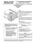
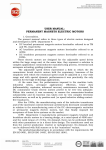
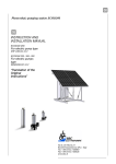
USER MANUAL
DC TORQUE MOTOR
The present manual shows an opportunity for the servomechanisms
builders of choosing the DC torque motors, with high performances, low
price and immediate delivery.
ICPE SA Department 4 designs and manufactures DC permanent
magnets torque motors whose windings are optimized so that a maximum
torque within overall size (housing outside diamater): 1.5 inch…5.1 inch can
be obtained.
1.Features of the DC torque motor.
These motors are designed in such a way as to function in direct-drive
construction. The fixed element – the stator, is equipped with permanent
magnets and the rotor with a DC specific winding which is connected to an
extra-flat commutator – brushes system; the rotor can perform a continuous
rotation and the main advantages of this construction are:
Lack of the gear or the mechanical multiplier;
Direct mounting on the leading shaft;
High useful mechanical torque at low speeds;
Big ratio: torque/inertia moment;
Linear characteristic of the useful mechanical torque function
the speed;
Big ratio: useful mechanical torque/power;
Time electrical constant: small;
Noise and vibration- free operation;
Simple but solid construction.
This electro-mechanical construction allows the servosystem
designer to obtain the following advantages:
Rigid coupling;
Quick response to the controls;
Static positioning: accurate;
Dynamic positioning: accurate;
Consumed electrical power: low;
The servosystem operates without any noise and vibrations;
The servosystem can be designed in a compact construction;
High reliability.
The DC direct-drive construction torque motor is equivalent to a DC
servomotor with a gear or mechanical multiplier but, because of the latter’s
absence (gear / mechanical multiplier), the servosystem is ideal for very fast
accelerations or decelerations. The lack of the gear in the system eliminates
the errors caused by the frictions, the clearances among the gear sides and
other mechanical accuracy errors, determines a very high positioning
sensitivity-arc seconds. This positioning sensitivity firistly depends on the
transducer detection accuracy-feed-back (synchro, resolver, encoder) which
is directly coupled onto the load shaft.
The DC torque motor offers a perfect linearity M = f(ω), in relation
to the AC two-phase servomotor (Fig.1) due to the fact that the frictions are
constant compared to those of the other one, where they are variable
function the speed and the control voltage. The performance of the DC
torque motor can be estimated accurately enough by using the linearity
conventional hypotheses of the servosystem. Thus, the servosystem time
mechanical constant has the same magnitude order (milliseconds) as that of
an AC servomotor. In any case, the effective time constants of the AC low
power servomotors for low positioning speeds are twice up to five times
smaller in comparison with the catalogue values. In this case, the higher
values are determining factors for the establishing of the system stability.
On the other hand, the time electric constant of a DC torque motor is very
small (fractions of milliseconds). In a system with performances of the 2nd order,
the time electric constant is that which determines the system stability. Due
to the linear characteristics of the DC torque motor, they are recommended
for being used in the servosystems requesting a position tracking accuracy
within the speed range from several thousandes up to one. The dynamic
regime is about ten times faster than that of the AC servomotor.
Fig.1 Torque-Speed characteristic of the DC torque motor
compared to that of the AC servomotor.
2. Operating equations.
The DC torque motor has a construction similar to that of a DC classic
motor, consequently there can be used its operating equations
U = E+IRM
(2.1)
E = KEω
(2.2)
T = KTI
(2.3)
where:
U – supply voltage [V];
E – back electromotive force (back EMF) [V];
RM (R) – DC resistance of the rotor winding [Ώ];
T - torque [Nm];
ω – rotation angular speed rad/sec];
KT - torque constant;
KE (KB) – back EMF constant;
If in equation (2.1) ther are introduced equations (2.2) and (2.3), there
results:
U = KE ω +
T R
KT
(2.4)
where: the first term of equation (2.4) represents the part of the supply
voltage necessary to produce the motor back EMF at the requested speed
and the 2nd term represents the part of the supply voltage necessary to
produce requested torque.
The torque motors can satisfactorily operate practicaly at any level of
supply voltage without the essential change of the mechanical
characteristics: the power, torques, and electro-mechanical constants
remain unchanged. Fig.2 shows the equivalent diagram of the torque motor.
L
where: the
ratio represents the time electric constant. The L
R
component stands for the armature inductivity and can be minimized
through an adequate design of the magnetic circuit.
Fig.2 Equivalent circuit of DC brushed motor
Energy relations.
If equation (2.1) is multiplied by the absorbed current I, then there
results the power balance:
UI = EI + RI2
(2.5)
The first term of equation (2.5) represents the absorbed power, the
second term (EI) stands for the mechanical power (W) developed in the motor
shaft which includes the friction and iron losses, the third term represents
the copper losses. The mechanical power developed in the motor shaft
results from equation (2.6):
EI =
T
0.007062
(2.6)
Under short – circuit conditions, equation (2.6) becomes:
TP 0
(2.7)
0,007062
where: ω0 is the no-load theoretical speed (without the losses effect).
Heat considerations: the absorbed winding electrical power is changed
into mechanical power deweloped by the rotor on one hand, as well as into
calorific power dissipated in the winding, on the other hand. For this reason,
the user must have in view that the motor overtemperature should not
exceed its insulation class and, at the same time, the operating critical
temperature of the magnets which, generally, are made of rare earths.
3. Construction.
From a constructive viewpoint, one distinguishes two types of DC
torque motors: torque motors with and without commutator.
3.1. Torque motors without commutator. These consist of two
armatures:
stator, made up of stamped and glued laminations, equipped with
a ring type winding; beacause of this construction, the cogging
torque is null;
rotor provided with permanents magnets. Figure 3.1.1 shows the
construction of this type of torque motor.
This construction limits the domain of the rotor rotation movement
which is function the number of the rotor pole pairs; consequently these
motors are called limited angle torque motors. Figure 3.1.2 shows the
mechanical feature corresponding to a four-pole construction.
3.2 Torque motors with commutator. Unlike the first type, these
motors have a reversed construction – the stator is equipped with
permanent magnets and the rotor is similar to that of a DC classic motor
(Fig.3.2).
Pp =
Fig. 3.1.1
Fig.3.1.2
The rotor lamination stack is made up slot, stamped and glued
laminations within which a DC winding is distributed and connected to the
commutator.
As far as the commutator is concerned, it can have a classic
construction if the length – outside diameter ratio is overunitary and if this
ratio is underunitary, ICPE SA Department 4 has developed a technology
enabling the attachment of the commutator directly to the front side of the
winding. The brush block assembly with the commutator brushes is carried
out in a detachable construction and it is operational by being attached to
the stator housing by the user – it is delivered separately.
The commutator brushes are of the silver-graphite type and the springs
which are made from bronze-beryllium also represents the paths of current.
With the two types of torque motors, ICPE SA Department 4 uses, for
the achievement of the armatures with permanent magnets, the SPM-type
technology (surface mounted permanent magnet); on demand, there can
also be used IPM technology (inside mounted permanent magnet).
Fig. 3.2
4. Definition of the electromechanical parameters.
4.1. Torque motors without commutator.
Peak torque Tp [N.m]
This electromagnetic torque is obtained under short-circuit conditions,
at a current IP, in the reference position of the rotor: α = 0º (Fig.3.1.2);
Angular range α [deg]
This is the angular operating range;
Power PP [W]
This is the power absorbed at the peak torque; computed value: RMIP2;
T
N.m
Motor constant KM [
]; this is the value computed by: P
W
PP
The supply voltage Up [V]
This is the voltage required to obtain current IP with the winding at
25ºC;
Peak current IP [A]
This is the motor current consumption required to obtain the peak
torque with the winding at 25ºC;
Maximum current Imax [A]
This is the value given for the metal permanent magnet type motors
below wich there is no risk of demagnetization;
Resistance RM [Ώ]
This is the resistance viewed from the motor output leads measured at
25ºC;
N.m
Torque constant KT [
]
A
The electromagnetic torque at 0.25IP (or at another value mentioned in
the specification) divided by the current value;
Back EMF constant KE [V/rad/s]
This is the induced voltage/speed ratio when the motor is driven at
1000 rev/min (or at another value mentioned in the specification);
Time electrical constant e [ms]
With the rotor locked, this is the time taken by the current to reach
U
63% of the value
, where U is the voltage required to obtain 0.25IP;
MM
Time mechanical constant m [ms]
J R
This is the value computed by using the equation: m = m M
KT K E
Static friction torque TF [cN.m]
This is themotor dry friction torque (mainly of magnetic origin)
Viscous damping coefficient F0 [N.m/rad/s]
This is the value computed by using the equation: F0 =
KT K E
;
RM
Heat constant TT [ºC/W]
This is the winding temperature rise versus the motor dissipated power.
This value is measured on a thermally insulated motor in calm atmosphere.;
The winding maximum temperature Δθ [ºC]
This value depends on the insulation class of the magnet wire and the
electro-insulating materials;
Rotor inertia Jm [g.cm2]
This is the measured inertia for the motor rotating armature;
Maximum theoretical acceleration [rad/s2]
This is the value computed by using the equation:
=
TP
.
Jm
4.2 Torque motors with commutator
Peak torque Tp [N.m]
This electromagnetic torque is obtained under short-circuit conditions,
at a current IP. This is the average of the torque values measured in both
directions of rotation and in both directions of power supply;
Power at peak torque PP [W]
Absorbed power corresponding to the peak torque;
Motor constant KM [
T
N.m
]; this is the value computed by: P
W
PP
Electrical time constant e [ms]
With the rotor locked, this is the time taken by the current to reach
U
63% of the value
, where U is the voltage required to obtain 0.25IP;
MM
Time mechanical constant m [ms]
J R
This is the value computed using the equation: m = m M ;
KT K E
Static friction torque TF [N.m]
Average of the friction torque values measured on a motor which is not
energized and is driven at a very low speed (a few rev/min)
Viscous damping coefficient F0 [N.m/rad/s]
K KE
This is the value computed by using the equation: F0 = T
;
RM
Ripple torque TR [%]
T
Tmin
This is the value computed by using the equation: TR = 100 max
, at
Tmax Tmin
a current of 0.25IP or at another value mentioned in the specification;
Heat constant TT [ºC/W]
This is the winding temperature rise versus the motor dissipated power.
This value is measured on a thermally insulated motor in calm atmosphere;
The winding maximum temperature Δθ [ºC]
This value depends on the insulation class of the magnet wire and the
electro-insulating materials;
Rotor inertia Jm [kg.m2]
This is the measured inertia for the motor rotating armature;
Maximum no-load speed ωNL [rad/s]
This is the value computed by using the equation: ωNL = UP / KE;
The supply voltage Up [V]
This is the voltage required to obtain the current IP with the winding at
25ºC;
Peak current IP [A]
This is the motor current consumption required to obtain the peak
torque with the winding at 25ºC;
Resistance RM [Ώ]
This is the resistance viewed from the motor output leads measured at
25ºC;
N.m
Torque constant KT [
]
A
The electromagnetic torque at 0.25IP (or at another value mentioned in
the specification) divided by the current value;
Back EMF constant KE [V/rad/s]
This is the induced voltage/speed ratio when the motor is driven at
80% of the maximum no-load speed;
Inductance LM [mH]
This is the value computed by using the equation: LM = e.RM.