1
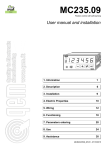
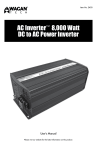
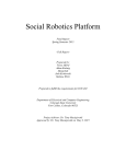
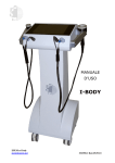
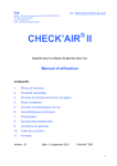
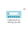
USER MANUAL MITOS VT6 AIR release software 3.1 Summary: GENERAL DESCRIPTION ............................................................................................................................................. 3 GENERAL FEATURES ................................................................................................................................................... 3 FUNCTIONING PARAMETERS .................................................................................................................................... 4 MITOS VT6 AIR FUNCTIONING MODE ..................................................................................................................... 7 FUNCTIONING JUST DISPLAY ..................................................................................................................................... 7 MANUAL FUNCTIONING ............................................................................................................................................. 8 AUTOMATIC FUNCTIONING (PID CONTROL)......................................................................................................... 9 PRESSURE / VELOCITY / FLOW RESET .................................................................................................................. 11 RESET INVERTER ALARM ........................................................................................................................................ 11 SELECTION OF SERIAL COMMUNICATION TTL/RS485 ...................................................................................... 11 CONNECTION FOR PRESSURE MEASURE / REGULATION................................................................................. 12 CONNECTION FOR FLOW OR VELOCITY MEASURE/REGULATION................................................................ 14 MECHANICAL DIMENSIONS .................................................................................................................................... 15 APPENDIX ..................................................................................................................................................................... 16 2 / 17 GENERAL DESCRIPTION MITOS VT6 AIR is a measure, visualization and control device for pressure, velocity and flow. It has got a differential pressure sensor with a +/-999mmH2O +/-1% F.S. range and a temperature sensor (internal). The precision of the pressure measurement is optimized by the compensation in function of the temperature. It is equipped with 6 buttons and 1 LCD 16x2 lines display (2 lines and 16 fonts each line). It is also programmable by a menu. The control is done by a VF-S11, VF-FS1, VF-AS1 or VF-PS1 Toshiba inverter, using a simple TTL serial connection (VF-S11 inverter) or RS485 (VF-FS1, VF-AS1, VF-PS1 inverter) and it can be manual or automatic. The selection of the type of serial connection can be selected by a dip-switch placed on the back of the box. Manual control allow to command run/stop and/or the inverter frequency. The frequency sent is fixed and is programmable from the display menu. Automatic control commands run/stop and also regulate the frequency sent to the inverter in order to keep the pressure, velocity or flow (selectable) at a fixed level, programmable from the display menu. Automatic control uses a PID regulation characterized by proportional, integrative and derivative parameters, changeable from the programming menu. MITOS VT6 AIR can also visualize some functioning parameters of the inverter, such as current and power delivered, input and output voltage, frequency, hours of functioning, historic of the last four alarms. Available scales for pressure, velocity and flow are: Pressure: mmH2O; mbar; Pascal; Kpascal. Velocity: second meter Flow: hundreds of cube meters per hour; cube meters per second; litres per second. GENERAL FEATURES MITOS VT6 AIR has got the following features Case: Alimentation: Working temperature: Box dimensions: Weight: Input: User interfaces: Material: ABS. IP55 protection degree The alimentation is directly taken by the inverter through the serial connecting cable From -5 to +50 °C 120 x 65 x 35 mm. 350g. 1 differential pressure gauge with +/-999mmH2O +/-1% F.S. Monocromatic graphic display 2x32 types, 6 buttons (START, MAN/AUTO, UP, DOWN, MON, STOP/RESET) 3 / 17 FUNCTIONING PARAMETERS The parameters programming menu is accessible in the normal functioning menu, by pushing MON button for at least 3 seconds. After the 3 seconds, it is necessary to insert a password. With UP and DOWN, you can change the number referred to the password, between 0 and 999. Once set the correct value, press MON to confirm. Each wrong password value allows to view just a part of the available parameters, the first eight in the following pattern. In the programming menu, you can select the parameter with the buttons UP and DOWN. Then, when the parameter is selected, the parameter will flash pressing the button MON. Value can be changed through buttons UP and DOWN. To store the new value, you need to press again MON (the parameter stops flashing). To quit the programming menu, just press MAN/AUTO. Here follow all the functioning parameters of MITOS VT6 AIR. PARAMETER Hysteresis FUNCTION POSSIBLE VALUES If the PID control is enabled, this act only if: min = 0; max (2) appendix V > Set point PID + Hysteresis or V < Set point PID - Hysteresis where V is the value measured by the controlled variable Constant PID Kp Constant PID Ki Constant PID Kd ACC manual DEC manual ACC automatic DEC automatic Mode Rotation sense PID control proportional constant PID control integrative constant PID control derivative constant Value of the ACC parameter sent to the inverter when Type command = MANUAL. Value of the DEC parameter sent to the inverter when Type command = MANUAL. Value of the ACC parameter sent to the inverter when Type command = AUTOMATIC. Value of the DEC parameter sent to the inverter when Type command = AUTOMATIC. MITOS VT6 AIR can be used as a simple display, but it can also send run and/or frequency variation commends to the Inverter Sense of engine rotation Feedback Type of variable where the control PID is performed Pressure unit Pressure Unit of measurement 0.0 ÷ 300.0 0.0 ÷ 300.0 0.0 ÷ 300.0 0.1 ÷ 320.0 sec. 0.1 ÷ 320.0 sec. 0.1 ÷ 320.0 sec. 0.1 ÷ 320.0 sec. COMMAND VISUALIZATOR AHEAD BACK PRESSURE VELOCITY FLOW mmH2O Pa kPa mBar m3 / h (value per 100) m3 / s l/s Flow unit Flow Unit of measurement Velocity unit PID Set point Velocity Unit of measurement Set the set-point of the variable where the PID control is performed PID Type Type of PID control m/s min = 0; max (2) appendix PID PI P PD 4 / 17 proport.-integr.-derivat. proport.-integr. proportional proport.-derivat. PID ACC/DEC delay Velocity calculation In AUTOMATIC mode, Inverter starts working through ACC/DEC ramps equal to ACC MANUAL/DEC MANUAL. When the controlled variable reaches the set-point, ACC/DEC are automatically set to the values ACC AUTOMATIC / DEC AUTOMATIC. This configuration remains till the stop of the Inverter. If the controlled variable does not reach the setpoint within PID ACC/DEC Delay seconds from the start, ACC/DEC are set to the values ACC AUTOMATIC/DEC AUTOMATIC Type of velocity calculation. The setting AIR has to be used in case the fluid present in the pipe is air. Otherwise, you may use the GENERIC setting. During velocity calculation with the section AIR, you need to set also the fluid temperature in °C, through the parameter Fluid Temperature. The calculation of the velocity with GENERIC setting is base on the following formula:: v=k P 0-999 sec. GENERIC AIR [m/s] where k = Velocity Constant (settable) and P is the differential pressure in mmHH2O. Pipe type Sets the pipe section. Pipe diameter Pipe side 1 Pipe side 2 Fluid temperature Circular pipe diameter (mm) Rectangular pipe’s side 1 size (mm) Circular pipe’s side 1 size (mm) Temperature of the fluid in the pipe (°C) Speed constant Language Sets the constant value in the generic formula for Sets the language of the menu Command type If the MITOS VT6 AIR is enabled to send commands to the inverter (Mode = COMMAND) and it has the complete control of the inverter (run-stop and frequency variation (1)), the Command type parameter determines the way the commands are sent Sets the monitor variable shown in the first line of the normal functioning display menu. Var. monitor1 will be visualized only in the following cases: Var. monitor1 RECTANGUL. CIRCULAR 0 2000 mm 0 2000 mm 0 2000 mm 0 200 °C 0.01 99.99 GERMAN ITALIAN ENGLISH SPANISH MANUAL AUTOMATIC (PID) see appendix (3) Mode = MONITOR or Var. monitor2 1) Mode = COMMAND 2) the MITOS VT6 AIR has only the run/stop command (1) Sets the monitor variable shown in the second line of the normal functioning display menu. Var. monitor2 will always be visualized and can be changed pushing UP and DOWN buttons while keeping F2 key pushed. But in this case the selection will be kept only until the device is on 5 / 17 see appendix (3) Set point manual Store set point Sets the value of the frequency sent to the inverter in MANUAL functioning. This value can be modified from the normal functioning menu It allows to store automatically or not the set point variation chosen with the UP and DOWN keys. Selecting YES, the set point variation (of the frequency or of the variable regulated in the PID control) from the normal functioning menu, is automatically stored. Selecting NO, the set point variation is not automatically stored and when you turn on the device again the value reloaded is the one saved using the parameters programming menu. 6 / 17 0.0 500.0 Hz YES NO MITOS VT6 AIR FUNCTIONING MODE The possible functioning modes of MITOS VT6 AIR are: Just display: it displays just the values of some parameters (3) Frequency Manual: it displays the values of some parameters (3) and it has just the control of the frequency Start/Stop Manual: it displays the values of some parameters (3) and it has just the manual control of the start/stop Complete Manual: it displays the values of some parameters (3) and it has the manual control of the start/stop and of the frequency Automatic PID: it displays the values of some parameters (3) and it has the automatic control (PID) of the frequency. The automatic control can have the start/stop control. You have the Just display mode through the setting of Modality parameter to the value VISUALIZATOR. All the other functioning modes are reachable setting the parameter Modality to the value COMMAND or changing CMOD, FMOD and command Type, as described in the appendix (1). It is possible to set the Modality parameter just through the parameters programming menu. If the Modality parameter is set on COMMAND, the setting of parameter command Type is possible through the programming menu and through the normal functioning menu, pressing for at least 3 seconds the button MAN/AUTO. The continuous pressure MAN/AUT allows to change the value from AUTOMATIC to MANUAL, and vice versa. Pressing the button MAN/AUTO for less then 3 seconds, you can only see the type of functioning selected at the moment. FUNCTIONING JUST DISPLAY In the JUST DISPLAY mode, MITOS VT6 AIR allows to display just: some parameters of the Inverter measured pressure or velocity or flow set-point (frequency set-point, or pressure/velocity/flow set-point) In appendix (3) you can find the complete list of the parameters. In the first line of the display you can find the information selected through the parameter Variable Monitor 1. In the second line of the display, after the card start, you can find the information selected through the parameter Variable Monitor 2. However, through the keys UP and DOWN, it is easy to reach all the other information available. 7 / 17 MANUAL FUNCTIONING In manual functioning, the MITOS VT6 AIR allows to control run-stop and/or change the frequency of inverter functioning, to a fix value which can be set through the parameter manual Set point. To enable the manual functioning the following points are necessary: Modality = CONTROL Control type = MANUAL It is possible to set the Modality only by the programming menu. If the Modality parameter is set to COMMAND, the setting of the parameter command Type is possible through the programming menu and through the normal functioning menu, pressing for at least 3 seconds the button MAN/AUTO. The continuous pressure MAN/AUT allows to change the value from AUTOMATIC to MANUAL, and vice versa. Pressing the button MAN/AUTO for less then 3 seconds, you can only see the type of functioning selected at the moment. The possibility to control just the run-stop, just the frequency or both, depends on the CMOD and FMOD values of Inverter, as shown in the appendix (1). If the MITOS VT6 AIR has the frequency control (1), you will see the real frequency reference value in the first line of the display. Otherwise, in case of lack of frequency control, in the first line of the display you will see the information selected through the parameter Variable Monitor 1. In the second line of the display, after the card start, you can find the information selected through the parameter Variable Monitor 2. However, through the keys UP and DOWN, it is easy to reach all the other information available. The value Manual Set point can be changed through the parameters programming menu and through the normal functioning mode. In this last case, if the Set point Storing is set on YES, the change of the set point is automatically stored and it will be kept even when the card is off; otherwise, if this parameter is set on NO, the change of the set-point won't be stored. The change of the Manual Set Point from normal functioning menu is performed as follows: 1. 2. 3. 4. with keys UP and DOWN, program "Set" in the second line of the display press the button MON (the second like will flash) change the value through UP and DOWN press the button MON (the second line will stop flashing and the value will be stored) If the MITOS VT6 AIR has the run-stop control, (1), pressing START the inverter will start work; pressing STOP/RESET the inverter will stop. When the inverter is in start and the engine is in spin, in the first line of the display, on the right side, it appears a symbol to indicate the rotation way. In the manual functioning, ACC and DEC Inverter parameters are automatically set equal to the values of ACC manual/ DEC manual parameters. 8 / 17 AUTOMATIC FUNCTIONING (PID CONTROL) In automatic functioning, the MITOS VT6 AIR does an automatic regulation of the frequency sent to the inverter so as to maintain the controlled variable (pressure, speed or flow) to a settable fixed value through the parameter Set point PID. The sent frequency will have like limits the values of parameters UL (upper limit) and LL ( lower limit) set up in the inverter, that’s will be always: UL frequency unchanged LL The regulation uses a control type PID, P, PI, PD, which can be selected through the parameter Type PID. To enable the automatic regulation, it is necessary that: Modality = CONTROL Control type = AUTOMATIC MITOS VT6 AIR must have the complete control frequency variation (1) The Modality setting is possible only from parameters programming menu. If the parameter Modality is set up on COMANDO, the Control type is possible is possible also from normal functioning menu, pressing more than 3 seconds button MAN/AUTO. The continuous pressure of MAN/AUTO allows to change the value from AUTOMATIC to MANUAL and vice versa. Pressing the button MAN/AUTO for less than three seconds you will only see the functioning selected at the moment. The setting of reference value (Set point PID) can be varied from menu programming parameters menu and also from the menu of normal operation. In this case, if the parameter Store set point is set on YES, the changing of set point is automatically stored and it will remain even if the card is turned off and on again; on the other hand, if this parameter is set on NO, the set point changing won't be stored. The variation of Set point PID from the menu of normal operation is carried out as follows: 1. 2. 3. 4. through buttons UP and DOWN set up “ SET” on the second line of the display press the MON button (the second line flashes) through buttons UP and DOWN vary the value press the MON button (the second line stop to flash and the value comes acquired) If MITOS VT6 AIR has the march-arrest control (1), pressing the button START, the inverter start, pressing the button STOP/RESET the inerter stops. When the inverter it’s in start and the motor is in rotation, in the first line of the display a little symbol appears on the right and this indicates the direction of rotation. After the command of start, the operation is manual with fixed set-point frequency, as the value of the inverter UL parameters and ACC/DEC ramps with the same value of ACC manual/ DEC manual parameters respective. When one of the two condition are verify: an equal time to second delay ACC/DEC PID passes the controlled variable catches up the set-point control PID of the frequency enters automatically in function and moreover, ACC/DEC ramps comes set up respective to the ACC automatic/DEC automatic parameters. Below there is a graphical representation of what is said previously 9 / 17 The meaning f the several numbers is the following one: 1. 2. 3. 4. moment in which there is the start moment in which the controlled variable is catches up the set-point and starts the PID regulation moment in which there is the stop equal time to the value of the Delay ACC/DEC PID after which PID regulation enter however in function The figure “a” is relative to the case in which between the start and stop inverter the controlled variable never doesn’t catch up the set point. The figure “b” is relative to the case in which between the start and stop inverter the controlled variable catch up the set point ( in correspondence of the point 2). The purpose of the two couples of different ramps in manual and automatic is to allow a slower answer during the startup, a quicker one when you are working at full speed. If the system can be led to instability (permanent waver), an empirical way to find the values of integrative, derivative and proportional constants is the following one: 1) Set Ki and Kd to zero 2) Staring from Kp low, increase Kp slowly to reach a waver of controlled variable 3) Reduce Kp at the half of precedent value 4) If necessary, increase Ki to bring to zero errors in stationary system 5) If necessary, increase Kd to speed up the answer If you change the unit of measurement to the controlled variable, you need to calibrate again the PID parameters. 10 / 17 PRESSURE / VELOCITY / FLOW RESET Due to the change of weather conditions, humidity etc., pressure or flow or speed viewed on the display, can change lightly on equal pressure on the sensor. To restore the correct value, you need to reset the offset. To do this, you may press at the same time the buttons STOP/RESET and MON when the engine is not working yet, and the vents of pressure sensor are both opened. CAUTION! The reset has to be performed only when the size on the display (pressure, velocity or flow) with open vent is different from zero, when the device is on since at least 15 minutes. RESET INVERTER ALARM In the case in which the inverter it had to go in alarm, TO INV REG visualizes to display the same code of alarm visualized on the display of the inverter. To reset the alarm is enough to press button STOP/RESET. SELECTION OF SERIAL COMMUNICATION TTL/RS485 Depending on the kind of inverter used, the dip-switch with two levers on the back of the box, has to be configured as follows: VF-S11 1=ON 2=ON VF-FS1 1=OFF 2=OFF VF-AS1 1=OFF 2=OFF 11 / 17 VF-PS1 1=OFF 2=OFF CONNECTION FOR PRESSURE MEASURE / REGULATION The pressure measure/regulation must be performed using the connections of the following figure FILTERED OUTPUT PRESSURE PIPE VT6 AIR DRAIN COCK (OPTIONAL) FAN CONSTANT PRESSURE It is recommended the use of filtered outputs to limit possible damages to the internal pressure sensor. These filtered outputs thwart the dust or other elements to go up to the pressure sensor and to small elements to obstruct the flow into the pipes. It is possible not to use the filtered outputs, but to the detriment of the instrument. The filtered outputs have to be mounted directly on the filter, where there are usually the air outputs pipes. It is necessary to install a filtered output for each pressure pipe, applied when necessary. In the following image, you can see the particular of a filtered output. 12 / 17 FILTER WALL 4 IMPLANTATION HOLES Ø3,75 PACKING IN RUBBER Ø20 HOLES LOW PRESSURE (3-5 Ø4 IN THE CENTER WITHIN A DIAMETER OF 20mm) SCREW Ø4,25 13 / 17 WADDING CONNECTION FOR FLOW OR VELOCITY MEASURE/REGULATION For velocity and flow regulation it’s necessary to use the Pitot Pipe applied to the vent of MITOS VT6 AIR. The choice of Pitot pipe lenght has to be made following the dimensions of the pipe, in order to put it at least up to the central part of the tubing. VT6 AIR 14 / 17 MECHANICAL DIMENSIONS Legend: 1: Pressure negative Input 2: Pressure positive Input 3: Connector for serial connection 4: TTL/RS485 serial line selector 5: Fixing brackets The pipes connected to the pressure sensor must have an internal diameter of 4 mm 15 / 17 APPENDIX (1) If Modality parameter is set on COMMAND, the control type of MITOS VT6 AIR on inverter is fixed by the parameter settings CMOD and FMOD of inverter, and by the Command Type parameter, as you can see in the following chart: Manual Frequency Manual Start/Stop Manual Complete Automatic PID (with start/stop) Automatic PID (without start/stop) VF-S11 CMOD 1 FMOD = 4 Command type: MANUAL CMOD = 1 FMOD 4 Command: MANUAL CMOD = 1 FMOD = 4 Command type: MANUAL CMOD = 1 FMOD = 4 Command type: AUTOMATIC CMOD 1 FMOD = 4 Command type: AUTOMATIC VF-FS1 CMOD 2 FMOD = 4 Command type: MANUAL CMOD = 2 FMOD 4 Command type: MANUAL CMOD = 2 FMOD = 4 Command type: MANUAL CMOD = 2 FMOD = 4 Command type: AUTOMATIC CMOD 2 FMOD = 4 Command type: AUTOMATIC VF-AS1 CMOD 2 FMOD = 5 Command type: MANUAL CMOD = 2 FMOD 5 Command type: MANUAL CMOD = 2 FMOD = 5 Command type: MANUAL CMOD = 2 FMOD = 5 Command type: AUTOMATIC CMOD 2 FMOD = 5 Command type: AUTOMATIC VF-PS1 CMOD 2 FMOD = 5 Command type: MANUAL CMOD = 2 FMOD 5 Command type: MANUAL CMOD = 2 FMOD = 5 Command type: MANUAL CMOD = 2 FMOD = 5 Command type: AUTOMATIC CMOD 2 FMOD = 5 Command type: AUTOMATIC (2) The maximum values which can be set for Set point PID and Hysteresi in case of pressure, velocity and flow are: Pressure: mmH2O: Pa: kPa: mBar: 9999 9999 99.99 9.99 Velocity: m/s: 999.9 Flow: m3/h: m3/s: l/s: 32767 3276.7 32767 16 / 17 (3) Possible values and its meaning for parameters Variable monitor 1 and Variable monitor 2 SET POWER CURRENT VIN VOUT ALARM1 ALARM2 ALARM3 ALARM4 CNT TEMPERATURE PRESSURE/VELOCITY/FLOW FREQUENCY frequency or pressure or velocity set point programmed * real power in kW absorbed by the engine real current absorbed by the engine, measured in Ampere tension in Volt in inverter input tension in Volt in engine input last alarm next to last alarm third from last alarm fourth last alarm hours counter temperature measured in grades centigrades value of measured pressure/velocity/flow * real frequency of inverter functioning * “frequency” if the functioning is MANUAL; one of the remaining, if the functioning is AUTOMATIC. In this second case, the selection between "pressure", "velocity" and "flow" depends on the value of Feedback parameter. ** the selection between “pressure”, “velocity” and “flow” depends on the value of Feedback parameter. 17 / 17