1
CET s.r.l.
A402
MESSAGE
DISPLAY
User manual
Version 1.1
CET s.r.l. - S.S. 211 Km 53 28071 Borgolavezzaro (NO)
Tel. 0321-885180 / 885301 FAX. 0321-885560
CET s.r.l.
MESSAGE DISPLAY A402
INDEX
1. INTRODUCTION .......................................................................................... 5
1.1. MAIN CHARACTERISTICS ......................................................................................... 5
1.2. TECHNICAL FEATURES ............................................................................................ 6
2. WORKING DESCRIPTION........................................................................... 7
2.1. SEQUENCES AND ALARMS VISUALIZATION .......................................................... 7
2.2. PROGRAMMABLE FUNCTIONS ................................................................................ 7
2.2.1.
2.2.2.
FUNCTION MENU AND THEIR ENTERING ....................................................................8
FUNCTIONS DESCRIPTION ...........................................................................................9
2.2.2.1.
2.2.2.2.
2.2.2.3.
2.2.2.4.
2.2.2.5.
2.2.2.6.
2.2.2.7.
2.2.2.8.
Alarms display mode ......................................................................................................................9
Alarm acknowledgment mode ........................................................................................................9
Input functions ..............................................................................................................................10
Input contact polarity ....................................................................................................................10
Parameters ...................................................................................................................................11
General working ...........................................................................................................................11
Output functions ...........................................................................................................................11
Timing message ...........................................................................................................................12
2.3. PROGRAMMED LOGICS MANAGEMENT (PLC)..................................................... 13
2.3.1.
2.3.2.
2.3.3.
2.3.4.
MAIN TABLE OF COMMANDS ......................................................................................13
MESSAGE MANAGEMENT............................................................................................14
VARIABLE ENTERING AND MANAGEMENT ................................................................15
SERVICE COMMANDS..................................................................................................17
2.3.4.1. Service commands description ....................................................................................................17
2.4. ELECTROMECHANICAL CONTACTS MANAGEMENT ........................................... 20
2.4.1.
2.4.2.
FUNCTIONS FOR 16 INPUTS .......................................................................................20
FUNCTIONS FOR 64 INPUTS WITH MUX EXPANSION ..............................................21
3. TECHNICAL DESCRIPTION...................................................................... 22
3.1. INPUTS...................................................................................................................... 22
3.1.1.
INPUT CONFIGURATION IN THE DIFFERENT FUNCTIONS.......................................22
3.1.1.1. Coded inputs from PLC ................................................................................................................22
3.1.1.2. Inputs from electromechanical CONTACTS.................................................................................23
3.1.1.3. Input from MUX electromechanical CONTACTS .........................................................................23
3.1.2.
TEMPORARY OPERATIONS ON THE INPUT COMMANDS.........................................24
3.2. OUTPUT CONFIGURATIONS AND CONNECTIONS............................................... 24
3.3. SERIAL LINE ............................................................................................................. 26
3.3.1.
SERIAL LINE COMMANDS............................................................................................26
3.4. CLOCK ...................................................................................................................... 27
3.4.1.
CHRONOLOGICAL ALARMS RECORDING ..................................................................27
4. FRONT KEYS OPERATIONS AND COMMANDS ..................................... 28
4.1. DESCRIPTION OF THE FUNCTIONAL COMMAND KEYS ...................................... 28
4.1.1.
4.1.2.
Operations with one key .................................................................................................28
Operations with two keys operated with the shown sequence ........................................29
4.2. KEYS DESCRIPTION FOR PROGRAMMING COMMANDS (ON THE MENU)........ 29
5. TEXT AND FUNCTION PROGRAMMING.................................................. 31
5.1. TEXT ORGANIZATION ............................................................................................. 31
pag. 1
MESSAGE DISPLAY A402
CET s.r.l.
5.2. FUNCTION ORGANIZATION ....................................................................................31
5.3. PROGRAMMING BY KEYBOARD.............................................................................31
5.3.1.
5.3.2.
Main level....................................................................................................................... 32
TEXT PROGRAMMING ................................................................................................. 32
5.3.2.1.
5.3.2.2.
5.3.2.3.
5.3.2.4.
5.3.2.5.
5.3.2.6.
5.3.3.
FUNCTIONS PROGRAMMING...................................................................................... 34
5.3.3.1.
5.3.3.2.
5.3.3.3.
5.3.3.4.
5.3.3.5.
5.3.3.6.
5.3.3.7.
5.3.3.8.
5.3.4.
5.3.5.
5.3.6.
5.3.7.
5.4.
5.5.
5.6.
5.7.
5.8.
Alarm display mode ......................................................................................................................34
Alarm acknowledgment mode ......................................................................................................34
Input function ................................................................................................................................34
Input contact polarity ....................................................................................................................34
Parameters ...................................................................................................................................35
General functioning ......................................................................................................................35
Output functions ...........................................................................................................................35
MESSAGGI A TEMPO .................................................................................................................35
TEXT VISUALIZATION .................................................................................................. 35
FUNCTION VISUALIZATION......................................................................................... 36
PRINT ............................................................................................................................ 36
DIAGNOSTICS .............................................................................................................. 36
5.3.7.1.
5.3.7.2.
5.3.7.3.
5.3.7.4.
5.3.7.5.
5.3.8.
Edit ...............................................................................................................................................32
Copy .............................................................................................................................................33
Compress .....................................................................................................................................33
Print ..............................................................................................................................................33
Progr. Transmission .....................................................................................................................33
Memory format .............................................................................................................................33
Hardware diagnost. ......................................................................................................................37
Input/output diagnostic .................................................................................................................37
Display diagnostic.........................................................................................................................37
Serial line diagnost. ......................................................................................................................37
Clock.............................................................................................................................................37
LANGUAGE CHOICE .................................................................................................... 38
PROGRAMMING WITH FRONT KEYS .....................................................................38
PROGRAMMING WITH SAMPLE MESSAGE DISPLAY ..........................................38
PROGRAMMING WITH PERSONAL COMPUTER...................................................39
PROGRAMMED MEMORY FILE ...............................................................................39
CHART OF THE AVAILABLE CHARACTERS ..........................................................39
6. ACCESSORIES ..........................................................................................41
6.1. KEYBOARD TS58 .....................................................................................................41
6.1.1.
DESCRIPTION OF THE KEYS ...................................................................................... 41
6.1.1.1. ORGANIZATION AND ACCESS TO MENUS..............................................................................42
6.1.2.
EDIT COMMANDS......................................................................................................... 43
6.1.2.1. Keys for characters writing ...........................................................................................................43
6.1.2.2. Command keys.............................................................................................................................44
6.2. ST40 PRINTER..........................................................................................................46
6.2.1.
6.2.2.
TECHNICAL FEATURES............................................................................................... 46
INSTALLATION ............................................................................................................. 47
6.3. “FV1” SOFTWARE PROGRAMS FOR PC MS-DOS AND ITS USE .........................48
6.3.1.
FV1 PROGRAM ............................................................................................................ 48
6.3.1.1. Installation ....................................................................................................................................48
6.3.1.2. Use guide file................................................................................................................................48
6.3.1.3. Symbols and hints ........................................................................................................................48
6.3.1.4. Created files .................................................................................................................................48
6.3.1.5. Program start................................................................................................................................49
6.3.1.6. Main menu ....................................................................................................................................49
6.3.1.7. Text management menu...............................................................................................................49
6.3.1.8. Text file creation ...........................................................................................................................49
6.3.1.9. Note for the displays with RAM memory ......................................................................................51
6.3.1.10. Text file change ..........................................................................................................................51
6.3.1.11. Text file view ...............................................................................................................................51
pag. 2
CET s.r.l.
MESSAGE DISPLAY A402
6.3.1.12.
6.3.1.13.
6.3.1.14.
6.3.1.15.
6.3.1.16.
6.3.1.17.
6.3.1.18.
Text file printing ..........................................................................................................................51
Text file removal .........................................................................................................................51
Conversion of a text file into an absolute file ..............................................................................52
Absolute file printing ...................................................................................................................52
Eprom programming...................................................................................................................52
Details about the use of the software of the eprom programmers sunshine type ......................52
"SERIAL" PROGRAM (For message displays with RAM memory and serial line).....................53
6.4. MULTIPLEXER DEVICE MUX 64/A .......................................................................... 54
6.4.1.
6.4.2.
6.4.3.
TECHNICAL FEATURES ...............................................................................................54
CONNECTIONS AND USE ............................................................................................54
A402 - MUX64A CONNECTION DIAGRAMS .................................................................55
7. TERMINAL BOARD AND MECHANICAL PART DIMENSIONS ................ 56
7.1. CONNECTION SCHEMES AND TERMINAL BOARDs ............................................. 56
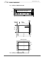
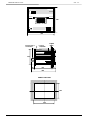
OVERALL DIMENSIONS ................................................................................................... 57
7.2.1.
7.2.2.
OVERALL DIMENSIONS A402 ......................................................................................57
OVERALL DIMENSIONS ST40 ......................................................................................57
pag. 3
MESSAGE DISPLAY A402
pag. 4
CET s.r.l.
CET s.r.l.
1.
MESSAGE DISPLAY A402
INTRODUCTION
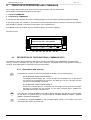
The A402 message display is a diagnosis device equipped with a 80 character alphanumeric display on two
lines, which shows the Operator a series of written information relative to certain situations.
The information is represented by messages which can be composed of 2 up to 8 lines each. Each line can have
a length up to 64 characters (generally 60 characters are used), with automatic scrolling of the writing in case the
maximum length of the display is exceeded (40 characters).
The scrolling writing is limited to the first display line, for simplification reasons.
All texts are entered and the stored in the message display through a suitable keyboard (TS 58 CE for
EUROPEAN characters or TS58 CI for CYRILLIC and INTERNATIONAL characters). As an alternative, text
programming can also be carried out by a serial connected PERSONAL COMPUTER. In this case, it is possible
to keep files relative to programming carried out on the different devices.
Furthermore, each display is capable, through a serial line, to transferring its programs into other devices, or to
carry out relative lists on the appropriate printer ST40.
The messages contained in the message display are recalled and managed on display according to various
procedures, both through the parallel interface of the COMMANDS (20 INPUTS) and through the suitable
SERIAL RS232 interface.
Furthermore, the text on display can be completed (or managed) through the entering of ASCII or BCD
characters (VARIABLES) directly to its inputs.
The display is equipped with programmable FUNCTIONS which make it suitable both for PROGRAMMABLE
LOGICS (PLC) and independent electromechanical CONTACTS.
On the front panel of the device there are 8 keys available, with which the Operator can directly carry out both
display commands and main FUNCTION programming, and also some specific visualization commands
occurred and stored sequences and relative printer lists.
Below some functions and fields where such message display is particularly suitable:
• Information about conditions or function sequences of a machine with relative diagnostics in case of shut
down.
• Chronological information and alarm recording.
• Alarm definition guide with 8 message lines.
• Sequence information of the setting at work operations with direct display of possible entered data
(variables).
• Information about maintenance operations.
• Troubleshooting sequences.
• Sequence information in different languages (8 lines).
1.1.
⇒
⇒
⇒
⇒
⇒
⇒
⇒
⇒
⇒
⇒
⇒
⇒
⇒
⇒
⇒
⇒
⇒
⇒
⇒
⇒
MAIN CHARACTERISTICS
Visualization on a fluorescent alphanumeric two lines display with 40 characters per line.
Punctiform character with 5x7 matrix, h= 5 mm with high brightness.
Complete ascii set availability (96 characters) + cyrillic set.
Possibility to enter up to 512 messages composed of 2 to 8 lines each for a maximum total of about 30.000
characters.
Written messages with a length up to 64 characters (if exceeding 40 characters there is an automatic lateral
scrolling).
Text programming with suitable keyboard or with pc through a serial line rs232 or by other already
programmed displays.
Entering completely guided by a suitable menu with the possibility to select 6 different languages.
Set of functional keys on the frontal for manual interface with the operator.
Direct message management by plc with coded parallel commands on 16 lines or in rs232 series.
Direct message management by 16 inputs for electromechanical contacts.
Management of up to 64 messages for the relative electromechanical contacts with extension card “mux64”.
Different management and codification for alarm and sequence visualization.
Message visualization on display according to two different programmable methods.
Alarm priority storage and visualization (up to a maximum of 64).
Programmable and addressable signals on 4 outputs.
Possibility of entering on display “variables” in ascii o bcd in any position.
Printing of the stored events with chronological time information (max. 128 events).
Programmable functions.
Built in diagnostics.
Power supply MULTI-VOLTAGE 24-110-220 Vac
pag. 5
MESSAGE DISPLAY A402
CET s.r.l.
⇒ Connections with removable terminals or connectors.
⇒ Front panel din 72 x 288 with protection degree ip65.
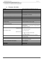
1.2.
TECHNICAL FEATURES
POWER
FREQUENCY
ABSORPTION
WORKING TEMPERATURE
STORAGE TEMPERATURE
CLIMATIC CONDITIONS
VISUALIZATION
: MULTI-VOLTAGE 24-110-220 Vac +10% -15%
: 50 - 60 Hz
: 10 VA
: -5 °C % + 50 °C
: -35 °C % + 70 °C
: R.H. 95 % AT 40 °C (with no c ondensate)
: 40 punctiform alphanumeric characters (H 5 mm) with
high brightness, on two lines
MESSAGE NUMBER (CAPACITY)
: 512 + WAIT. MESS. + COMMON. MESS.
MESSAGE COMPOSITION
: from 2 to 8 LINES each
LINE LENGTH
: 64 CHARACTERS MAXIMUM
TEXT MEMORY
: RAM for a total capacity of about 30.000 characters
FUNCTION AND ALARM MEMORY
: RAM (for a maximum of 64 ALL)
CHRONOLOGICAL MEASURE MEMORY
: RAM (for a Maximum of 128 measures)
MEMORY AUXILIARY POWER
: Battery Ni.Cd. in buffer with an autonomy of about 2
(for data reserve)
years and duration of over 10 years.
NUMBER OF VARIABLES THAT CAN BE ENTERED : as many characters as the corresponding text.
(with external commands)
INPUTS
: PRI input for POSITIVE or NEGATIVE LOGIC
programming
: DATA inputs NR. 20 (see table), all opto-isolated, for
the different functions.
0 = 0 Vdc % 6 Vdc
: POSITIVE logic
1 = 10,5 Vdc % 28 Vdc
INPUT SIGNAL LEVEL
1 = 0 Vdc % 3 Vdc
: NEGATIVE logic
0 = OFF from OPEN COLLECTOR
or
0 = 12 Vdc % 30 Vdc.
(connecting PRI to the terminal Vdc POWER)
INPUT AUXILIARY POWER
: 12 Vdc - 100 mA supplied to the terminal board by the
message display
SERIAL INTERFACE
: RS232 with cannon connector with 9 poles
SERIAL CHARACTERS
: all characters available on display with some of the
main command characters
SERIAL PROTOCOL
: 1 START Bit, 9 DATA Bits, PARITY NONE, 2 STOP
(common in transmission and reception)
Bits, 1200 BAUD
CONNECTIONS
: with removable terminals
PROTECTION DEGREE ON THE FRONT PANEL
: IP 65
EXECUTION
: DIN 72 X 288
ASSEMBLY
: Built in, fixed with suitable squares.
pag. 6
CET s.r.l.
2.
MESSAGE DISPLAY A402
WORKING DESCRIPTION
2.1.
SEQUENCES AND ALARMS VISUALIZATION
The "SEQUENCES" are all the operations carried out by a certain machine in consecutive times (machine
CYCLES).
In case of a logic or a series of contacts capable to identify the different cycles, it is possible, through the
message display, to visualize all the machine sequences, thus allowing the operator to know at anytime which
function is being carried out.
In the message display the different SEQUENCES are not stored, but only scanned in time by the movement of
the contacts or by the input logics commands.
The "ALARMS” are occasional events representing a machine malfunctioning and can be temporary,
continuous, single or multiple.
Their recording, in case of breakdowns, allows to discover the cause of the malfunctions and to identify all the
occurred inconveniences.
The ALARM resolution (removal of the cause), also in selective mode (one by one)and their recording reset,
allow to point out possible connections between one alarm and another.
In case of alarm survey by contact, it can be useful to operate with N.C. contact connection wire safety.
The A402 message display gives, with a single instrument, the possibility to analyze all the events occurring on
machines or plants.
In fact, the SEQUENCES can be visualized and simultaneously it is possible to keep under control all the
ALARMS of a machine. All ALARMS are stored and are thoroughly managed, both in visualization and in
acknowledgment.
The message display has a BUFFER for the chronological recording of 128 alarm addresses, containing the last
128 alarms occurred at any time, each one with date and time.
An operational BUFFER allows to store and process up to 64 ALARMS, with programmable management
characteristics.
In case of coded logics the alarm can be entered and then acknowledged (cleared) in a completely addressed
way (singularly)
In case of contacts, every single alarm can be acknowledged in a conditioned way, that is only if the respective
input has gone home.
In any case, from the front keys it is possible to know how many ALARMS are in memory, which one has arrived
first and which one last. It is also possible to review them one by one and in case, to reset them singularly or in
programmed way.
Each alarm is always followed by the DATE and TIME of the moment when it occurred
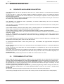
2.2.
PROGRAMMABLE FUNCTIONS
Before using this device it is necessary to program it. Such an operation can be divided into two main parts:
message TEXT PROGRAMMING and FUNCTION PROGRAMMING, that is the functioning of the device itself.
All programmings can be carried out with the suitable KEYBOARD (TS58 CE / TS58 Cl) whose specific use will
be described later; the function programmings can be carried out also with the front keys. If necessary, it is also
possible to program the texts with the front keys.
Two other programming methods are represented by external programming obtained through the serial line,
through PERSONAL COMPUTER or by another MESSAGE DISPLAY (also the FV1 series or A402) already
programmed.
All operations regarding the physical programming of the device are described in paragraph 5.
The following paragraphs describe the structure and meaning of all the FUNCTIONS of the message display.
pag. 7
MESSAGE DISPLAY A402
CET s.r.l.
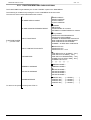
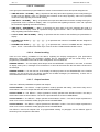
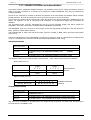
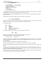
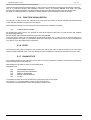
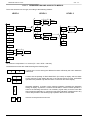
2.2.1. FUNCTION MENU AND THEIR ENTERING
The FUNCTIONS are generated by the "FUNC. PROGR." option in the MAIN MENU.
Their entering is conditioned by writing the correct code SYS in the shown boxes.
The structure of the FUNCTIONS follows the scheme:
ALARMS DISPLAY MODE
ALARM ACKNOWLEDGMENT MODE
COMMON
SELECTIVE
CONDITIONED for contacts
AUTOMATIC CONDITIONED for contacts
INPUT FUNCTIONS
(PLC) CODED
CONTACTS FOR SEQUENCES
CONTACTS FOR ALARMS
ALARMS +8 SEQUENCES CONTACTS
MUX CONTACTS FOR SEQUENCES
MUX CONTACTS FOR ALARMS
ALARMS + 32 SEQ. MUX CONTACTS
INPUT CONTACTS POLARITY
CONTACTS N.A.
CONTACTS N.C.
CONTACTS N.C. + N.A
FUNCTION PROGR.
[ . . . ] Access Code
PARAMETERS
GENERAL WORKING
OUTPUTS WORKING
TIMING MESSAGE
To return to the previous menu press CTRL+C
pag. 8
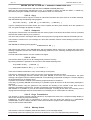
SINGLE DIRECT
SINGLE INVERSE
CYCLIC DIRECT
CYCLIC INVERSE
TIME RELAYS 2 for ALARMS [ .. Sec.]
TIME OUT3 for ALARMS [ .. Sec.]
TIME OUT4 for SEQUENCES [ .. Sec.]
ALARM CYCLIC SCAN. TIME [ . Sec.]
ALARMS FOR "OUT3"
[...][...][...][...]
GENERAL MODE 1
GENERAL MODE 2
OUTPUTS MODE 1
OUTPUTS MODE 2
OUTPUTS MODE 3
OUTPUTS MODE 4
1>MESS. NR. [ . . . ] > HOURS
2>MESS. NR. [ . . . ] > HOURS
3>MESS. NR. [ . . . ] > HOURS
4>MESS. NR. [ . . . ] > HOURS
[......]
[......]
[......]
[......]
CET s.r.l.
MESSAGE DISPLAY A402
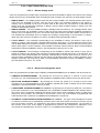
2.2.2. FUNCTIONS DESCRIPTION
2.2.2.1. Alarms display mode
There are grouped all the possible ways of presenting the stored ALARMS on display of the device: the message
display can store up to 64 ALARMS; when exceeding the 64th message, the oldest one is automatically cleared.
• SINGLE DIRECT - The display always shows the last entered ALARM. The message flashes when there is
more than one ALARMS in memory. With the S4 key (ADV), the messages regarding to the alarms in
memory can be reviewed one by one in inverse order to the arrival one. The arrival of a new Alarm will
directly show the corresponding message on display. After the 64th ALARM message in memory, the first
entered is automatically cleared.
• SINGLE INVERSE - The first ALARM message is displayed (the first entered). The message flashes when
there is more than one ALARMS in memory. With the S4 key (ADV) the messages regarding the alarms in
memory can be reviewed one by one in the arrival order (from the first to the last entered). The arrival of a
new ALARM will automatically show on display the message corresponding to the first alarm in memory.
When there are more than 64 alarms in memory, the oldest will be automatically cleared.
• CYCLIC DIRECT - The messages corresponding to the ALARMS in memory are shown in cyclic way on
display (in inverse order) and with a programmable scanning time (from I to 9 seconds).The arrival of any
new ALARM displays the respective message, as in the direct visualization, and from this the scanning of the
alarms starts again. In these conditions, some suitable commands, with front KEYS, allow a manual detailed
examination of all the ALARMS in memory. See descriptions of the keys S1, S4, S5.
• CYCLIC INVERSE - The messages corresponding to the ALARMS in memory are shown in cyclic way on
display (according to the arrival order) and with a programmable scanning time (from I to 9 Seconds). The
arrival of any new ALARM displays the message corresponding to the first alarm arrived in memory, as in
with the inverse visualization, and from this the scanning of all alarms starts again. In these conditions, some
suitable commands, with front KEYS, allow a manual detailed examination of all the ALARMS in memory.
See descriptions of keys S1, S7, S4, S5.
2.2.2.2. Alarm acknowledgment mode
There are grouped all the possible ways to RESET (ACKNOWLEDGMENT) the ALARMS in the device memory.
• COMMON ACKNOWLEDGMENT - By pressing the S7 Front key (ACK) for 3 seconds or by the input
command 117, the acknowledgment of the ALARMS in COMMON mode is started, that is they are all reset.
• SELECTIVE ACKNOWLEDGMENT - By pressing the S7 front key (ACK) for 3 seconds or by the input
command 117, the acknowledgment of the ALARMS in SELECTIVE mode is started, that is the message
regarding the first entered alarm in memory is reset.
• CONDITIONED ACKNOWLEDGMENT for contacts - By pressing the S7 front key (ACK) For 3 seconds or
by the input command 117, the acknowledgment of the ALARMS in CONDITIONED mode is started: there is
the reset of all the messages regarding the alarms whose device inputs (message display or MUX) have
returned to home position. The execution of this function occurs only if the display is programmed with
CONTACTS function. Otherwise, a COMMON acknowledgment is carried out.
• AUTOMATIC CONDITIONED ACKNOWLEDGMENT for contacts - This type of acknowledgment requires
no external command, but is automatically executed, that is the input alarms are stored in memory and as
soon as the alarm is lacking, it is cleared from the memory (automatic acknowledgment). The execution of
this function occurs only if the display is programmed to function with CONTACTS. Otherwise, if the
commands are operated by the S7 key or in input 117, a COMMON acknowledgment is carried out.
pag. 9
MESSAGE DISPLAY A402
CET s.r.l.
2.2.2.3. Input functions
In this group are defined all the possibilities of use of the inputs in relation to the commands coming from the
system.
• CODED for PLC - The input commands are interpreted according to the suitable coded table. This type of
programming is used with PROGRAMMED LOGICS (PLC), that, through their internal program, manage all
the commands for the message display.
• CONTACTS for SEQUENCES - The input commands are interpreted according to the 16 INPUT
configuration, as shown in paragraph 7.1 and corresponding to SEQUENCE CONTACTS. To each input (IN0
... IN15) corresponds a SEQUENCE MESSAGE (from 0 to 15), that is shown on display when the respective
input is present. If more than one input is present at the same time, priority is given to the one with lowest
value (towards IN0).
• CONTACTS for ALARMS - The input commands are interpreted according to the 16 INPUT configurations
as shown in paragraph 3.1 and corresponding to ALARM CONTACTS. To each input (IN0 ... IN15)
corresponds a SEQUENCE MESSAGE (from 0 to 15) which is stored and managed in the message display
according to the functions received in the programming.
• ALM. + 8 SEQ. CONTACTS - The input commands are interpreted according to the 16 INPUT configurations
as shown in paragraph 3.1 and relatively to 8 ALARM contacts (IN0 ... IN7) and 8 SEQUENCE contacts (IN8
... IN15). The messages corresponding to the ALARM inputs have priority on those for the sequences and
work in the same way as described for the 16 alarms. When in the display memory there are no more
ALARMS, the message corresponding to the present sequence contact (input) is shown, in the way
described for the sequence inputs.
• MUX CONTACTS FOR SEQUENCES - The input commands are interpreted according to the 64 INPUT
configuration, as shown in paragraph 3.1 and corresponding to MUX SEQUENCE CONTACTS. To each
input (IN0 ... IN64) corresponds a SEQUENCE MESSAGE (from 0 to 64) corresponds to each input which is
shown on display when the respective input is present. If more than one input is present at the same time, the
one with the lowest value has priority (towards IN0).
• MUX CONTACTS FOR ALARMS - The input commands are interpreted according to the 64 INPUT
configurations, as shown in paragraph 3.1 and corresponding to ALARM CONTACTS. To each input (IN0 ...
IN64) corresponds an ALARM MESSAGE (from 0 to 64) to which is stored and managed in the display
according to the functions received during programming.
• CONTACTS 32 ALM + 32 SEQ MUX - The input commands are interpreted according to the 64 INPUT
configurations as shown in paragraph 3.1 and corresponding to the 32 ALARM contacts (IN0 ... IN31) and 32
SEQUENCE contact (IN32 ... IN63). The messages corresponding to the ALARM inputs have priority on the
sequence ones and work in the same way as the ones described for the 64 alarms. When no more ALARMS
are present in the display memory, the message corresponding to the present sequence contact (input) is
visualized, in the way described for the sequence inputs.
2.2.2.4. Input contact polarity
In this group are defined the significant modes assigned to the input contacts. These programmings are not
significant when the inputs are used in coded logics.
• CONTACTS N.C. - The display considers all input contacts as NORMALLY CLOSED (or closed at rest), so
the alarm or sequence will be activated on contact opening.
• CONTACTS N.A. - The display considers all input contacts as NORMALLY OPEN (or open at rest), so the
alarm or sequence will be activated on contact closing.
• CONTACTS N.C. + N.A. - The display considers the first half of the input contacts as NORMALLY CLOSED
(or closed at rest) and the second half as NORMALLY OPEN (or open at rest) and in particular if the input
programming is carried out as ALARMS + SEQUENCE, the N.C. contacts will be assigned to the ALARMS,
while the N.A. contacts will be assigned to the SEQUENCES.
pag. 10
CET s.r.l.
MESSAGE DISPLAY A402
2.2.2.5. Parameters
In this group are included the programmable time values of some timed functions and special assignments.
• TIME RELAYS 2 - ALARMS [ .. Sec.] - Represents the relays time value regarding to the recall (entering) of
an alarm into the display. Value "0" represents the exclusion of the relays signaling. Value "99" represents
continuous relays signaling until manual clearing.
• TIME OUT 3 - ALARMS [ . . Sec.] - It represents the output time value when an alarm message among the 4
programmed ones is recalled on display. Value "0" represents the signalling exclusion. Value "99" represent
the continuous signalling until manual clearing.
• TIME OUT4 - SEQUENCES [ ... Sec.] - It represents the time value of the OUT regarding the recall of a
sequence into the display. Value "0" represents relays signal exclusion. Value “99” represents continuous
relays signalling until manual clearing.
• CYCLIC SCAN. TIME ALARMS [ ... Sec.] - It represents the time value for the ALARM cyclic presentation on
display.
• ALARMS FOR "OUT3" [ ... ] [ ... ] [ ... ] [ ... ] - It represents the number of ALARMS that are assigned to
output "OUT3".
• ALARMS FOR “OUT4" [ ... ] [ ... ] [ ... ] [ ... ] - It represents the number of ALARMS that are assigned to
output “ OUT4”. These alarms are used only in case of OUTPUT FUNCTIONS in MODE 3 and 4.
2.2.2.6. General working
There are two working possibilities of the device, regarding the display management. (The performance
differences mainly regarding the messages recalling and its management with the frontal keys; all the
programming visualization forms and the men management are not influenced.
GENERAL MODE 1 – The two display lines always show one MESSAGE. It’s possible, in this case, to visualize
on display, time by time, messages of 80 characters or to show at the same time the text and the under text of
the message.
GENERAL MODE 2 – On the first line of the display are always present or the SEQUENCES or the WAITIN
message. On the second line are always showed the ALARM messages (40 characters); if there are no
memorized alarms will be show the data and time.
2.2.2.7. Output functions
There are 4 different possibilities to operate with outputs.
OUTPUT MODE 1 - The RELAY 1 output (operation contact) operates with safety, with excited relay and no
stored alarms. The OUT4 output indicates the recall of a SEQUENCE.
OUTPUT MODE 2 - The RELAY 1 output (operation contact) operates with standard function: the relay is
excited when there are stored alarms. The OUT4 output indicates the recall of a SEQUENCE.
OUTPUT MODE 3 - The RELAY 1 output operates as described in mode 1. The OUT4 output represents the
recall of one of the 4 ALARMS, suitably programmed in PARAMETERS.
OUTPUT MODE 4 - The RELAY 1 output Operates as described in mode 2. The OUT4 output represents the
recall of one of the 4 ALARMS, suitably programmed in PARAMETERS.
The RELAY 2 and OUT3 outputs have no programmable working. At paragraph 3.2 the different types of
functioning of all 4 outputs are described.
pag. 11
MESSAGE DISPLAY A402
CET s.r.l.
2.2.2.8. Timing message
In the device are available 4 clocks with programmable value set point, able to active 4 memorized messages
when the timings are ended
1>MESS.NR.[...]>ORE [......]
2>MESS.NR.[...]>ORE [......]
3>MESS.NR.[...]>ORE [......]
4>MESS.NR.[...]>ORE [......]
In the field shown by NR. enter the number of the alarm to recall, in the field shown by ORE enter the clock SET
time in hour in 6 digits, eith the non significave zeros.
Not correct selections excludes the entered values.
pag. 12
CET s.r.l.
2.3.
MESSAGE DISPLAY A402
PROGRAMMED LOGICS MANAGEMENT (PLC)
• Starting from the home position (reset of all eventual storages), the writing WAITING MESSAGE will appear
on display.
• Normally, if the text is longer than display length (40 characters), there is an automatic continuous scrolling
(from right to left) of the whole message.
• With the PLC it is possible to send two types of commands to the message display input in order to recall the
MESSAGES; one is associated with the meaning of recall for the SEQUENCE message, the other is
associated with the meaning of the recall for the ALARM message.
• The recalled SEQUENCE MESSAGE appears on display and isn't stored; the following sequence message
command clears the previous one and brings the new text on display. The recalled ALARM MESSAGE is
stored in chronological order; it has the priority on the sequence one for visualization and it is shown on
display according to the programming received for the alarm message visualization. Such a message can be
cleared (acknowledged) according to the suitable modes.
• Furthermore, other stored alarm messages can be visualized according to different automatic or manual
sequences.
• By entering service commands, the PLC can recall the various message lines on display (or ask for their
automatic management); such operations are also possible with the keys on the front panel. In the same way
all message lines of stored ALARMS can be managed.
• By entering suitable coded commands by suitable PLC, it is possible to manage and directly update
thoroughly or partly, certain areas of the message text on display, by entering the desired characters (ASCII
or BCD). In this way it is possible to complete the texts with values (VARIABLES) present in the system, for
example voltage, current, speed and times.
• Furthermore, various service commands are available for clearing the variables and messages, display
flashing, entering different lines, clock entering, executions, printing and others.
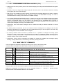
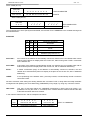
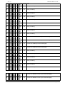
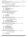
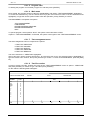
2.3.1. MAIN TABLE OF COMMANDS
The input signals are divided and managed according to the codes of the following table.
The inputs of the visualizator from IN0 to IN15 are here indicated from D0 to D15
TYPE “0”
command
TYPE “1”
command
TYPE “2”
command
TYPE “3”
command
TYPE “4”
command
TYPE “5”
command
SY
D15 D14
0
0
0
0
0
0
0
0
1
1
1
1
INPUTS
D13 D12 D11 D10 D9 D8 D7 D6 D5 D4 D3 D2 D1
0 0 0
SEQUENCE message recall in BINARY code
0 0 1
SEQUENCE message recall in BCD code
0 1 0
ALARM message recall in BINARY code
0 1 1
ALARM message recall in BCD code
1 0 0
POSITION entering of the VARIABLE in BINARY code
1 0 1
POSITION entering of the VARIABLE in BCD code
1 1 0
CHARACTER entering of the VARIABLE in ASCII code
1 1 1
CHARACTER entering of the VARIABLE in BCD code
0 0 0
Acknowledgment of the ALARM message in BINARY code
0 0 1
Acknowledgment of the ALARM message in BCD code
0 1 0
SERVICE COMMAND with number in BINARY code
0 1 1
SERVICE COMMAND with number in BCD code
The inputs D16--D19 are only used as impulsive commands, therefore they are not included in the table.
N.B. EACH COMMAND IS STORED ON THE SY CHANGE FROM 0 --> 1 (absent --> present) WHICH
OPERATES AS SYNCHRONIZED IMPULSE OR STROBE.
pag. 13
MESSAGE DISPLAY A402
CET s.r.l.
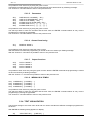
2.3.2. MESSAGE MANAGEMENT
Each message is associated with a number which identifies the sequence position in the composition memory.
In order to manage the message on display it its necessary to send to the display inputs the group of 16 data
with the shown code:
D14 D13 D12
X
X
X
COMMAND TYPE "0", "1", “4"
D11 = 0
INDICATES THAT THE MESS NUMBER TO BE MANAGED IS IN
"BINARY” CODE .
D11 = 1
INDICATES THAT THE MESS NUMBER TO BE MANAGED IS IN "BCD"
CODE.
The number of the message to be managed is situated in inputs D0 --- D10 if in BCD, in inputs D0---D8 if in
BINARY.
BCD CODE (D11=1)
2° digits
3° digits
2
2
1
2
0
3
2
2
D10 D9 D8
2
2
1
2
1° digit
0
3
2
D7 D6 D5 D4
HUNDREDS
2
2
1
2
0
2
2
D3 D2 D1 D0
TENS
BCD NUMBER
INPUTS
UNITS
BINARY CODE (D11=0)
-
-
8
2
7
2
6
2
5
4
2 2
3
2
2
2
1
2
0
2
D10 D9 D8 D7 D6 D5 D4 D3 D2 D1 D0
BINARY NUMBER
INPUTS
"0" TYPE COMMAND
It is used to recall a SEQUENCE MESSAGE on display. In this case the message is not stored and a
subsequent command of this type clears the sequence message and brings a new SEQUENCE message on
display.
"1" TYPE COMMAND
It is used to store an ALARM MESSAGE in the device.
The entering of an alarm is shown by an acoustic BEEP if there is the appropriate enabling.
The stored alarm messages assume priority on the sequence ones and are shown on display at once, according
to the programmed procedures and until they are completely acknowledge.
In the case of more than one ALARM in the message display memory, the corresponding message(s) are shown
in a flashing way.
"4" TYPE COMMAND
It is used to ACKNOWLEDGE (reset) an ALARM MESSAGE in the device.
The stored alarm messages can be cleared in selective mode, as they were recalled.
pag. 14
CET s.r.l.
MESSAGE DISPLAY A402
2.3.3. VARIABLE ENTERING AND MANAGEMENT
In the texts of all the messages recalled on display, it is possible to enter by PLC certain characters in order to
make up a word, a sentence or a number; such wording are called VARIABLES, since they are continuously
changed (updated).
First of all it is necessary to foresee in advance the positions in the texts where the variables will be inserted,
leaving them free. This can be carried out only for one part of the text, or for the whole text.
In any case, the variable can be entered only within the length of the text programmed in MEMORY and not
further. For example, if a text is composed of 30 characters, it is possible to manage only 30 positions as
variables.
The commands which must be transmitted by the PLC to the message display and which contain the
VARIABLE, are mainly composed of CHARACTERS e ADDRESS (POSITION).
THE ADDRESS (from 0 to N, where N is the length of the text) represents the address in the text where the
letter, symbol or number will be entered.
The CHARACTER, in ASCII code, will be the letter, symbol or number; in BCD code it will only be the number
(from 0 to 9).
The whole management of the VARIABLES is carried out by using the TYPE "2" command for the address and
TYPE “3” command for the character with all their eventual possibilities of sub-coding.
ADDRESS ENTERING
D14 D13 D12
0
1
0
COMMAND TYPE "2"
D11 = 0
IT SHOWS THAT THE ADDRESS NUMBER IS IN
CODE
"BINARY"
D11 = 1
IT SHOWS THAT THE ADDRESS NUMBER IS IN "BCD" CODE
The address number to be entered resides in the inputs D0 --- D6 if in BCD, and in D0--D5 if in BINARY.
BCD CODE ( D11=1)
2° digit
-
-
-
2
-
2
D10 D9 D8 D7
1
1° digit
0
2
3
2
2
2
D6 D5 D4
2
1
2
D3 D2 D1 D0
TENS
0
2
BCD POSITION
INPUTS
UNITS
BINARY CODE (D11=0)
-
-
-
-
-
D10 D9 D8 D7 D6
5
4
2 2
3
2
2
2
1
2
0
2
D5 D4 D3 D2 D1 D0
BINARY POSITION
INPUTS
CHARACTER ENTERING
D14 D13 D12
0
1
1
COMMAND TYPE "3"
D11 = 0
IT SHOWS THAT THE VARIABLE IS IN ASCII CHARACTER CODE
D11 = 1
IT SHOWS THAT- THE VARIABLE IS IN "BCD" CHARACTER CODE
The value of the VARIABLE to be entered is in the inputs among D0 and D3, if in BCD code, and among the
input D0 and D7 if in BINARY code.
pag. 15
MESSAGE DISPLAY A402
CET s.r.l.
ASCII CODE (D11=0)
Sub-code
7
X X X
2
D10 D9 D8
6
5
2
4
2
3
2
2
2
2
1
0
2
2
ASCII CHARACTER
D7 D6 D5 D4 D3 D2 D1 D0
INPUTS
BCD CODE (D11=1)
Sub-code
7
X X X
6
2
D10 D9 D8
5
2
2
4
3
2
2
2
D7 D6 D5 D4
1
2
2
0
2
BCD CHARACTER
D3 D2 D1 D0
INPUTS
The inputs D8--D10, which specify the SUB-CODE, are foreseen for the ADDRESS in the variable entering area
as indicated below:
SUBCODE
D10
D9
D8
carried out operations
0
0
0
AUTO INC
0
0
1
AUTO DEC
0
1
0
STOP
0
1
1
HOME
1
X
X
IND+BCD (only with D11=1)
AUTO INC :
An increase of the address is automatically carried out; therefore the next variable which will be
entered, will be placed on display after the current one, without using other TYPE 2 commands
for the address set.
AUTO DEC :
A decrease of the address is automatically carried out; therefore the next variable which will be
entered will be placed on display before the current one, with no additional addressing.
STOP :
A further confirmation (stop) of the address is automatically carried out; therefore, the next
variable to be entered will be placed on display in the place of the current one, with no additional
addressing.
HOME :
A new positioning to the address value, previously entered, is automatically carried out with the
command TYPE2.
All these subcodes, after setting the starting address with command TYPE 2, easily allow the totally automatic
management and updating of a whole data string (VARIABLES) of any length, by using only command TYPE3.
IND + BCD :
This type of sub-code makes the VARIABLE management in BCD code even easier. It is
possible to use only the TYPE "1" command, which contains both the address data and the data
of the BCD character data to be entered.
In this case the data from D0---D9 are interpreted as follows:
5
2
pag. 16
4
2
3
2
2
2
1
2
0
2
3
2
2
2
1
2
0
2
D10
D9 D8 D7 D6 D5 D4
D3 D2 D1 D0
1
ADDRESS (IN BINARY)
BCD VARIABLE
TYPE "3" COMMAND
CET s.r.l.
MESSAGE DISPLAY A402
2.3.4. SERVICE COMMANDS
The device is equipped with a series of FUNCTIONS which the PLC can enter by sending TYPE 5 coded
commands: SERVICES.
D14 D13 D12
1
0
1
COMMAND TYPE "5"
(SERVICES)
D11 = 0
IT SHOWS THAT THE NUMBER OF THE SERVICE COMMAND IS IN
"BINARY" CODE
D11 = 1
IT SHOWS THAT THE NUMBER OF THE SERVICE COMMAND IS IN
"BCD" CODE
The NUMBER of the SERVICE COMMAND (NCS) is found in the inputs D0 --- D7 if in BCD code and in the
inputs D0 --- D5 if in BINARY code (for a maximum of 32 available commands).
BCD COMMAND (D11=1)
2 digit
-
-
3
-
2
D10 D9 D8
2
2
1
2
1 digit
0
3
2
2
2
D7 D6 D5 D4
2
1
0
2
2
D3 D2 D1 D0
TENS
BCD NUMBER (NCS)
INPUTS
UNITS
BINARY COMMAND (D11=0)
-
-
-
-
5
4
2 2
-
D10 D9 D8 D7 D6
3
2
2
2
1
2
0
2
D5 D4 D3 D2 D1 D0
BINARY COMMAND (NCS)
INPUTS
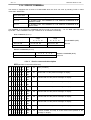
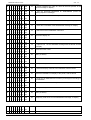
2.3.4.1. Service commands description
NCS (Number of Command of Service)
0 0 0 0 0 0 0 0 BCD
-
It shows LINE 4 of the present message on display
05
It shows LINE 5 of the present message on display
06
It shows LINE 6 of the present message on display
07
It shows LINE 7 of the present message on display
08
It shows LINE 8 of the present message on display
09
It moves forward one step at a time all the lines present in the
message on display
- 0 0 1 0 0 0 BIN
0 0 0 0 1 0 0 1 BCD
-
04
- 0 0 0 1 1 1 BIN
0 0 0 0 1 0 0 0 BCD
-
It shows LINE 3 of the present message on display
- 0 0 0 1 1 0 BIN
0 0 0 0 0 1 1 1 BCD
-
03
- 0 0 0 1 0 1 BIN
0 0 0 0 0 1 1 0 BCD
-
It shows LINE 2 of the present message on display
- 0 0 0 1 0 0 BIN
0 0 0 0 0 1 0 1 BCD
-
02
- 0 0 0 0 1 1 BIN
0 0 0 0 0 1 0 0 BCD
-
Shows LINE 1 of the present message on display
- 0 0 0 0 1 0 BIN
0 0 0 0 0 0 1 1 BCD
-
01
- 0 0 0 0 0 1 BIN
0 0 0 0 0 0 1 0 BCD
-
NULL (no effect)
- 0 0 0 0 0 0 BIN
0 0 0 0 0 0 0 1 BCD
-
00
- 0 0 1 0 0 1 BIN
pag. 17
MESSAGE DISPLAY A402
0 0 0 1 0 0 0 0 BCD
-
Previous function reset
20
NULL (no effect)
21
NULL (no effect)
22
NULL (no effect)
23
It sends the display contents to the PRINTER, with the DATE
24
Sends the VARIABLE on display to the printer, with the DATE
25
It sends the ALARM BUFFER contents (chronological recording) to
the PRINTER
26
It sends the ALARMS in memory to the PRINTER
27
NULL (no effect)
28
NULL (no effect)
29
Temporary recall of the current SEQUENCE message on display
30
Current serial TRANSMISSION reset
31
NULL (no effect)
- 0 1 1 1 0 1 BIN
0 1 1 0 0 0 0 0 BCD
-
19
- 0 1 1 1 0 0 BIN
0 0 1 0 1 0 0 1 BCD
-
It replaces line 1 of the WAITING message with the DATE CLOCK
on display
- 0 1 1 0 1 1 BIN
0 0 1 0 1 0 0 0 BCD
-
18
- 0 1 1 0 1 0 BIN
0 0 1 0 0 1 1 1 BCD
-
It turns the display on
- 0 1 1 0 0 1 BIN
0 0 1 0 0 1 1 0 BCD
-
17
- 0 1 1 0 0 0 BIN
0 0 1 0 0 1 0 1 BCD
-
It turns the display off
- 0 1 0 1 1 1 BIN
0 0 1 0 0 1 0 0 BCD
-
16
- 0 1 0 1 1 0 BIN
0 0 1 0 0 0 1 1 BCD
-
It clears the entered VARIABLE characters
- 0 1 0 1 0 1 BIN
0 0 1 0 0 0 1 0 BCD
-
15
- 0 1 0 1 0 0 BIN
0 0 1 0 0 0 0 1 BCD
-
It resets the FLASHING of the SEQUENCE message on display.
- 0 1 0 0 1 1 BIN
0 0 1 0 0 0 0 0 BCD
-
14
- 0 1 0 0 1 0 BIN
0 0 0 1 1 0 0 1 BCD
-
It sets the FLASHING of the SEQUENCE message on display.
- 0 1 0 0 0 1 BIN
0 0 0 1 1 0 0 0 BCD
-
13
- 0 1 0 0 0 0 BIN
0 0 0 1 0 1 1 1 BCD
-
It resets all the ALARMS in memory.
- 0 0 1 1 1 1 BIN
0 0 0 1 0 1 1 0 BCD
-
12
- 0 0 1 1 1 0 BIN
0 0 0 1 0 1 0 1 BCD
-
It sets the WAITING MESSAGE for SEQUENCES (resets the
existing sequence message).
- 0 0 1 1 0 1 BIN
0 0 0 1 0 1 0 0 BCD
-
11
- 0 0 1 1 0 0 BIN
0 0 0 1 0 0 1 1 BCD
-
It moves backward one step at a time all the lines present in the
current message on display
- 0 0 1 0 1 1 BIN
0 0 0 1 0 0 1 0 BCD
-
10
- 0 0 1 0 1 0 BIN
0 0 0 1 0 0 0 1 BCD
-
CET s.r.l.
- 0 1 1 1 1 0 BIN
0 0 1 1 0 0 0 0 BCD
pag. 18
CET s.r.l.
-
- 0 1 1 1 1 1 BIN
0 0 1 1 0 0 1 0 BCD
-
CLOCK 1 It enables CLOCK 1 (for timed messages)
42
CLOCK 2 It enables CLOCK 2 (for timed messages)
43
CLOCK 3 It enables (for timed messages)
44
CLOCK 4 It enables (for timed messages)
45
NULL (no effect)
46
NULL (no effect)
47
NULL (no effect)
48
NULL (no effect)
49
NULL (no effect)
50
NULL (no effect)
51
CLOCK 1 It disables CLOCK 1 (for timed messages)
52
CLOCK 2 It disables CLOCK 2 (for timed messages)
- 1 1 0 0 1 1 BIN
0 1 0 1 0 0 1 0 BCD
-
41
- 1 1 0 0 1 0 BIN
0 1 0 1 0 0 0 1 BCD
-
NULL (no effect)
- 1 1 0 0 0 1 BIN
0 1 0 1 0 0 0 0 BCD
-
40
- 1 1 0 0 0 0 BIN
0 1 0 0 1 0 0 1 BCD
-
NULL (no effect)
- 1 0 1 1 1 1 BIN
0 1 0 0 1 0 0 0 BCD
-
39
- 1 0 1 1 1 0 BIN
0 1 0 0 0 1 1 1 BCD
-
NULL (no effect)
- 1 0 1 1 0 1 BIN
0 1 0 0 0 1 1 0 BCD
-
38
- 1 0 1 1 0 0 BIN
0 1 0 0 0 1 0 1 BCD
-
NULL (no effect)
- 1 0 1 0 1 1 BIN
0 1 0 0 0 1 0 0 BCD
-
37
- 1 0 1 0 1 0 BIN
0 1 0 0 0 0 1 1 BCD
-
NULL (no effect)
- 1 0 1 0 0 1 BIN
0 1 0 0 0 0 1 0 BCD
-
36
- 1 0 1 0 0 0 BIN
0 1 0 0 0 0 0 1 BCD
-
NULL (no effect)
- 1 0 0 1 1 1 BIN
0 1 0 0 0 0 0 0 BCD
-
35
- 1 0 0 1 1 0 BIN
0 0 1 1 1 0 0 1 BCD
-
NULL (no effect)
- 1 0 0 1 0 1 BIN
0 0 0 0 0 0 0 0 BCD
-
34
- 1 0 0 1 0 0 BIN
0 0 1 1 0 1 1 1 BCD
-
NULL (no effect)
- 1 0 0 0 1 1 BIN
0 0 1 1 0 1 1 0 BCD
-
33
- 1 0 0 0 1 0 BIN
0 0 1 1 0 1 0 1 BCD
-
NULL (no effect)
- 1 0 0 0 0 1 BIN
0 0 1 1 0 1 0 0 BCD
-
32
- 1 0 0 0 0 0 BIN
0 0 1 1 0 0 1 1 BCD
-
MESSAGE DISPLAY A402
- 1 1 0 1 0 0 BIN
pag. 19
MESSAGE DISPLAY A402
0 1 0 1 0 0 1 1 BCD
-
CET s.r.l.
53
CLOCK 3 It disables CLOCK 3(for timed messages)
54
CLOCK 4 It disables CLOCK 4 (for timed messages)
55
NULL (no effect)
56
NULL (no effect)
57
NULL (no effect)
58
NULL (no effect)
59
NULL (no effect)
60
NULL (no effect)
61
NULL (no effect)
62
NULL (no effect)
63
NULL (no effect)
- 1 1 0 1 0 1 BIN
0 1 0 1 0 1 0 0 BCD
0 0 1 1 0 1 1 0 BIN
0 1 0 1 0 1 0 1 BCD
-
- 1 1 0 1 1 1 BIN
0 1 0 1 0 1 1 0 BCD
-
- 1 1 1 0 0 0 BIN
0 1 0 1 0 1 1 1 BCD
-
- 1 1 1 0 0 1 BIN
0 1 0 1 1 0 0 0 BCD
-
- 1 1 1 0 1 0 BIN
0 1 0 1 1 0 0 1 BCD
-
- 1 1 1 0 1 1 BIN
0 1 1 0 0 0 0 0 BCD
-
- 1 1 1 1 0 0 BIN
0 1 1 0 0 0 0 1 BCD
-
- 1 1 1 1 0 1 BIN
0 1 1 0 0 0 1 0 BCD
-
- 1 1 1 1 1 0 BIN
0 1 1 0 0 0 1 1 BCD
-
- 1 1 1 1 1 1 BIN
2.4.
ELECTROMECHANICAL CONTACTS MANAGEMENT
• This device can be used with a direct connection to the contacts; in this case 16 inputs are available for a
maximum of 16 messages that can be recalled, or with connection through multiplexer card MUX64; in this
way there are up to 64 contacts available with their respective 64 messages.
• In any case, through function programming, it is possible to give the input contacts three different meanings:
SEQUENCE contacts, ALARM contacts, half contacts for ALARMS and half contacts for SEQUENCES.
• The messages will be activated or deactivated by contact functioning (opening or closing) according to the
different modes programmed in the respective function.
2.4.1. FUNCTIONS FOR 16 INPUTS
The connections in this configuration are illustrated. in paragraph 3.1.
In case of half ALARM and half SEQUENCE: programming, the inputs IN0..IN7 will be considered alarms and
the inputs IN8...IN15 sequences; furthermore, for N.C. + N.A. programming, the N.C. contacts will be given to
the alarms and the N.A. ones to the sequences.
When switching on the message display, the alarms present, will be detected according to the N.C. or NA
programming.
pag. 20
CET s.r.l.
MESSAGE DISPLAY A402
2.4.2. FUNCTIONS FOR 64 INPUTS WITH MUX EXPANSION
The connections in this configuration are illustrated in paragraph 3.1.
In case of half ALARM and half SEQUENCE programming, the inputs IN0..IN32 will be considered alarms and
the input IN32 ... IN63 sequences; furthermore, for N.C. + N.A. programming, the N.C. contacts will be given to
the alarms and the N.A. ones to the sequences.
When switching on the message display, the alarms present will be detected according to the N.C. or N.A.
programming.
pag. 21
MESSAGE DISPLAY A402
3.
CET s.r.l.
TECHNICAL DESCRIPTION
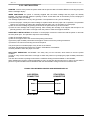
3.1.
INPUTS
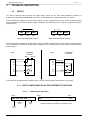
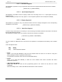
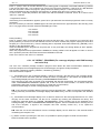
The device terminal board foresees 20 signal inputs, which can be used with POSITIVE LOGICS, by
programming the additional EARTHED input "PRI", or With NEGATIVE LOGICS with "PRI" at +12VDC.
The terminal board supplies an outside power supply of 12VDC (100mA) which can be used to control the inputs
as an alternative of the external power supply, according to the following scheme (only for programmed inputs in
positive logics).
PRI
+ 12
GND
PRI
+ 12
GND
23
10
22
23
10
22
INPUTS IN POSITIVE LOGICS
INPUTS IN NEGATIVE LOGICS
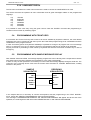
The terminal board supplies an outside power supply of 12VDC (100mA) which can be used to control the inputs
as an alternative to the external power supply, according to the following scheme (only for inputs programmed in
positive logics).
EXTERNAL
FEEDER
A402
GND
+ 24 Vdc
GND-GROUND
GND-GROUND
22
22
10
10
11
11
29
29
30
30
CONNECTOR
EXTERNAL
FEEDER
A402
CONNECTOR
CONNECTOR
+ 12 Vdc
CONNECTOR
If the inputs are programmed for negative logics, only the external earth communication is necessary
3.1.1. INPUT CONFIGURATION IN THE DIFFERENT FUNCTIONS
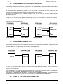
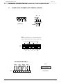
3.1.1.1.
Coded inputs from PLC
IN19
IN15
D19 D18 D17 D16
RELAY 2
Reset
OUT 3
Reset
pag. 22
D15 . . . . . . . . . .
OUT 4
Reset
Mess.
ACK
IN0
. . . D0
coded according to the chart in paragraph 2.3.1
CET s.r.l.
MESSAGE DISPLAY A402
3.1.1.2. Inputs from electromechanical CONTACTS
IN19
IN15
D19 D18 D17 D16
D15 . . . . . . . . . .
RELAY 2
Reset
OUT 3
Reset
IN0
OUT 4
Reset
. . . D0
to the 16 CONTACTS with programmed functions
Mess.
ACK
3.1.1.3. Input from MUX electromechanical CONTACTS
IN19
IN15
D19 D18 D17 D16
RELAY 2
Reset
OUT 3
Reset
IN0
D15 . . . . . . . . . .
OUT 4
Reset
. . . D0
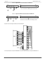
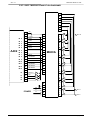
direct MUX connection, as in the following scheme
Mess.
ACK
Complete connection diagram between A402 and MUX64/A
S0
S1
S2
S3
S4
S5
S6
S7
23
A402
PRI
22
0
1
10
+ 12 Vdc
2
IN 0
11
INPUTS
3
IN 1
12
INPUTS
4
IN 2
13
INPUTS
5
IN 3
14
INPUTS
6
IN 4
15
INPUTS
7
IN 5
16
INPUTS
8
IN 6
17
INPUTS
9
IN 7
18
INPUTS
10
IN 8
19
MUX SIGNALS
11
IN 9
20
MUX SIGNALS
12
IN 10
24
MUX SIGNALS
13
IN 11
25
MUX SIGNALS
14
IN 12
26
MUX SIGNALS
15
IN 13
27
MUX SIGNALS
16
30
30
RES OUT 4
31
31
ACK
17
32
32
33
33
18
RES RL2
RES OUT 3
1A
2A
POWER
220
3A
110
4A
24
5A
0
6A
63
----56
INPUT 63
55
----48
MUX/A
47
----40
39
----32
31
----24
23
----16
15
----8
7
----0
INPUT 7
INPUT 0
To the input IN0 (D0) corresponds MESSAGE 0 and to the input IN15 (D15) corresponds MESSAGE 15.
pag. 23
MESSAGE DISPLAY A402
CET s.r.l.
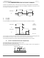
3.1.2. TEMPORARY OPERATIONS ON THE INPUT COMMANDS
In general, every single device input, in order to be read, must remain in a stable condition for at least 8 Msec.
All coded commands are stored on the significant variation (from ABSENT to PRESENT) of the signal in SY and
must respect the following min. time conditions:
coded inputs
SY
T1 T3
T2 T1
T3
COM1
T1
T2
T3
COM2
min. 1 Msec.
min. 9 Msec.
min. 9 Msec.
For a quick updating of the VARIABLES from PLC the use of a sequence is advisable, as follows:
FIRST
COMMAND
coded inputs
SY
SECOND
COMMAND
coded inputs
SY
10Msec 10Msec 10Msec 10Msec
ETC. ETC.
The input signals, managed with MUX64, answer with times from MUX; in general the total scanning time of the
64 input CONTACTS is (:)93 Sec., whether, there is only one input or they are all connected.
The 16 direct input CONTACTS to the device A402 are always tested with a min. time of 10 Msec.
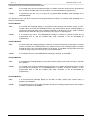
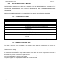
3.2.
OUTPUT CONFIGURATIONS AND CONNECTIONS
The message display has 4 output relays with operating contacts.
RL1 and RL2 are suitable for a 5A-250Vac load.
OUT3 and OUT4 can be used with a max. load of O,5A and a max. voltage of 120Vac. Their configuration on
the terminal board is shown in the following diagram.
OUT4 RL1 OUT3 RL2
39 40 41 42 43 44 45 46
pag. 24
CET s.r.l.
MESSAGE DISPLAY A402
The functions of RL2 and OUT3 OUTPUTS are fixed:
- RL2 :
It is excited every time an ALARM message is recalled. It remains excited for the programmed
time or until the suitable relay reset command. It can be disenabled by programming.
- OUT3 :
It operates as RL2 but only f or a group of 4 programmable ALARMS. (See paragraph 2.2.2
PARAMETERS).
The functions of RL1 and OUT4 OUTPUTS are programmable according to 4 methods (See paragraph 2.2.2
OUTPUT FUNCTIONS).
OUTPUT MODE 1
- RL1 :
It is excited with message display on and with no alarm present (rest contact closed). It is deexcited if there is at least one ALARM present in the inside memory of the message display. It
remains de-excited till there is the complete acquisition of all alarms. The RL1 reset command
with front keys resets the relay (only for the time you act) for an operating test.
- OUT4 :
It is excited every time a new SEQUENCE message is entered. It remains excited for the
programmed time or until the suitable relay reset command. It can be disenabled by
programming.
OUTPUT MODE 2
- RL1 :
It is de-excited with message display on and with no alarm present (rest contact open). It excites
if there is at least one ALARM present in the inside memory of the message display. It remains
excited till there is the complete acquisition of all alarms. The suitable command with front keys
excites the relay (only for the time you act) for an operating test.
- OUT4 :
It is excited every time a new SEQUENCE message is entered, as in MODE 1.
OUTPUT MODE 3
- RL1 :
It is excited with message display on and with no alarm present (rest contact closed). it operates
as in MODE 1.
- OUT4 :
It is excited every time an ALARM message, among the 4 suitably programmed for this output
(as indicated at paragraph 2.2.2 PARAMETERS) is recalled. It remains excited f or the
programmed time or until the suitable relay reset command. It can be disenabled by
programming.
OUTPUT MODE 4
- RL1:
It is de-excited with message display on and with no alarm present (rest contact open). It
operates as in MODE 2.
- OUT4 :
It is excited every time an ALARM message, among the 4 suitably programmed for this output is
recalled; it operates as in MODE 3.
pag. 25
MESSAGE DISPLAY A402
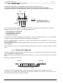
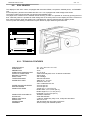
3.3.
CET s.r.l.
SERIAL LINE
The A402 message display is equipped with a RS232 serial line with fixed protocol:
1 START Bit, 8 DATA Bits, Parity NONE, 2 STOP Bits with transmission speed 1200 BAUD.
The physical connection is carried out through a female cup connector with 9 pins as shown in the picture:
RX
BUSY
OUT
TX
BUSY
IN
5
1
9
6
SHIELD
P1 P2
SI NO = COMMANDS RECEPTION
NO SI = PROGRAMMING RECEPTION
P1
P2
The two P1 and P2 bridges determine the type of connection and therefore the operations to be carried out.
With the serial line it is possible to carry out the following functions:
•
•
•
•
PROGRAMMING TRANSMISSION
TRANSMISSION TO PRINTER
PROGRAMMING RECEPTION.
COMMAND RECEPTION
The devices can transmit all programmed messages to another message display set in the "programmingreception" condition according to the procedure described in paragraph 5.3.
With the suitable SERVICE commands it is possible to directly pilot the ST40 PRINTER in order to print the
device visualization listings.
During programming with KEYBOARD, suitable MENU commands allow to list the texts of the entered message
on the PRINTER.
The message displays can be completely managed (controlled) with serial line commands instead of parallel
inputs.
3.3.1. SERIAL LINE COMMANDS
The device generating of the serial line command (a PC or a PLC LOGICS) must simply build the data string,
using the GENERAL COMMAND TABLE.
Each command will be composed of two words with 9 bits each, as shown in the picture and sent one after the
other:
Data string composition for command:
START BIT
2 STOP BITS
1
0
BIT BIT BIT BIT BIT BIT BIT BIT PARITÀ
0 1 2 3 4 5 6 7 NONE
The sequence of the transmitted bytes corresponds exactly to the sequence of the parallel commands.
The recovery of a possible byte synchronism loss between transmitter and receiver can be carried out by
sending 3 BYTES composed of contiguous ZEROS.
pag. 26
CET s.r.l.
3.4.
MESSAGE DISPLAY A402
CLOCK
The message displays are equipped with a perpetual calendar/clock.
With the suitable SERVICE command, it is possible to transfer the clock contents on display, instead of the
waiting message.
This information is visualized as in the following example:
"Mon. 4 Sept. 89 - 13:25:18”
From the front panel it is always possible, with suitable keys to visualize the clock contents.
In the devices equipped with connection to the PRINTER, the carried out listings are automatically equipped with
date and time, as follows:
MESS. 005 LINE 1
< 4/9/89 - 13:25 >
The time and date adjustment is carried out through the keyboard.
3.4.1. CHRONOLOGICAL ALARMS RECORDING
The device has an internal BUFFER to store in chronological order the ALARMS coming from the plant, each
one equipped with date and time when they occurred.
The capacity of this memory is 128 ALARMS with direct loading of the last entered and unloading of the oldest
one.
The whole BUFFER can be made available for PRINTER with a suitable command from the front keys.
This type of listing appears as in the example shown below.
MESS. 001
< 4/9/89 - 13:25 >
Message . . .. . . . . . . . . . . . . . . . . . . .
MESS. 005
< 3/9/89 - 17:31 >
Message . . .. . . . . . . . . . . . . . . . . . . .
MESS. 028
< 1/9/89 - 18:24 >
Message . . .. . . . . . . . . . . . . . . . . . . .
MESS. 071
< 1/9/89 - 11:09>
Message . . .. . . . . . . . . . . . . . . . . . . .
I
I
I
I
MESS. nnn
< 1/9/89 - 1040 >
Message . . .. . . . . . . . . . . . . . . . . . . .
pag. 27
MESSAGE DISPLAY A402
4.
CET s.r.l.
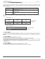
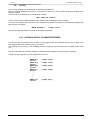
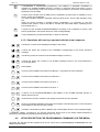
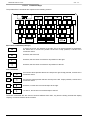
FRONT KEYS OPERATIONS AND COMMANDS
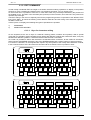
The message display front panel has 8 keys for a direct interface with the OPERATOR.
The available commands are divided into two types:
1. Function COMMANDS
2. Programming COMMANDS
In the first case the operator can ask the message display for the information regarding the plant functioning.
In the second case, it is possible to give the device some information about its working in the plant and it will be
also possible to operate on its internal composition of the message texts.
If the BEEP function is enabled, any key activation causes an acoustic signalling
Device front view
ALLARME TEMPERATURA MOTORE RINCIPALE
КOHTPOЛЪ ЭATTOЛH. ЛPECCФOPMЬI
ENT
1 LIN
2 NUM
S1 S2
4.1.
3 ALL
4 ADV
S3 S4
5 S/RUN
RES
MENU
S5 S6
ACQ
PRINT
S7 S8
DESCRIPTION OF THE FUNCTIONAL COMMAND KEYS
Here below are listed all the operations that can be carried out as FUNCTION COMMANDS, and their effect.
The key number or numbers (S1...S8) are given as a reference, and beside there is the operation mnemonic
meaning, those abbreviation is reported on the keys themselves.
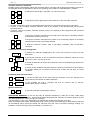
4.1.1. Operations with one key
It increases the number of LINE of the message on display ( only for existing lines ).
1 LIN
WITH GENERAL FUNCTIONING MODE 1
The display shows message line 1 on the first line and message line 2 on the second
line; with the S1 command for line increase, you obtain line 2 on line 1 and line 3 on line
2 and so on with following commands.
WITH GENERAL FUNCTIONING MODE 2
if there are no alarms present, it increases the line number for the sequence message;
otherwise it increases the line number for the alarm message and it displays the
message and line NR. on display line 1.
2 NUM
3 ALL
pag. 28
It visualize the message NUMBER and LINE on display with time and data when it was recalled
for the time it is pressed (only if it programmed as ALARMS DISPLAY MODE - SINGLE
DIRECT OR SINGLE INVERSE).
It visualizes the ALARM NUMBER in the message display memory, the number of the first
entered and the number of the last one.
CET s.r.l.
It INCREASES or DECREASES (respectively if the DIRECT or INVERSE visualization is
enabled) the ALARM NUMBER present in memory (in temporal order) and tranfer it on the
display. In functionning mode 2 for the time the key is pressed on the first line of the display is
showed the time and data.
3 ADV
It carries out the STOP of the ALARM CYCLIC visualization (if this function is enabled). If it is in
STOP, it stops the visualization.
The STOP condition remains in automatic mode for about 69 sec. from the last activation of any
key.
When the device operates in ALARM CYCLIC visualization, it is necessary to stop this
operation with STOP in order to be able to visualize the memorized alarms, operating on the
keys marked with ( * ).
ENT
5
MESSAGE DISPLAY A402
S/RUN
It carries out the ALARM ACKNOWLEDGMENT according to the conditions for which it has
been programmed in the specific functions of the message display;
RES
ACQ
If it is pressed during a serial transmission, it stops its execution.
PRINT
4.1.2. Operations with two keys operated with the shown sequence
It sends the contents of the displayed message to the printer.
PRINT
1 LIN
PRINT
2 NUM
PRINT
3 ALL
PRINT
4 ADV
It sends the printer the contents of all ALARM messages stored in the event BUFFER in
chronological order.
ENT
Not available
PRINT
5 S/RUN
It sends the printer the contents of the VARIABLE corresponding to the current sequence
message.
It sends the printer the contents of all ALARM messages in memory.
It carries out the RESET command for the RELAY 1 (considered as a test operation
RES
ACQ
1 LIN
It carries out the RESET command for the RELAY 2.
RES
ACQ
2 NUM
It carries out the RESET command for the OUT 3
RES
ACQ
3 ALL
It carries out the RESET command for the OUT 4
RES
ACQ
4 ADV
RES
ENT
ACQ
5 S/RUN
It transfers the CLOCK contents to the display for the time they are operated.
ENT
5 S/RUN
1 LIN
ENT
5 S/RUN
2 NUM
During the ALARM visualization it transfers the message corresponding to the current sequence
to the display for the time they are pressed.
It enables or disenables (in SET or RESET) the acoustic BEEP function in the message display.
ENT
5 S/RUN
It carries out the ACKNOWLEDGMENT (the RESET) of the ALARM message present on
display at that moment.
3 ALL
A GENERAL RESET command for the internal memorized alarms and for the whole EVENT BUFFER is
foreseen by simultaneously pressing of the three keys: SS + S7 + S5.
4.2.
KEYS DESCRIPTION FOR PROGRAMMING COMMANDS (ON THE MENU)
Here after are described all the operation that can be carried out as PROGRAMMING COMMANDS ON THE
MENU and their effect.
pag. 29
MESSAGE DISPLAY A402
CET s.r.l.
The key number or numbers (S1 ... S8) are given as a reference, and beside there is the operation mnemonic
meaning, whose abbreviations is reported on the same keys.
5 S/RUN
From the position of rest, it enters the programming menu. In the programming, it returns to the
position rest.
1 LIN
It scrolls UP the menu lines (this function is also carried out by the keyboard GREEN UP
cursor).
ENT
It scrolls DOWN the menu lines (this function is also carried out by the keyboard GREEN DW
cursor).
It carries out the ENTER in the same way as the keyboard; it enters all data or increases the
level.
2 NUM
ENT
5 S/RUN
RES
ENT
ACQ
5 S/RUN
PRINT
5 S/RUN
ENT
It carries out the inverse function of ENTER; it returns to the previous level; it is the equivalent
command of the keyboard “Control + C".
It carries out the programming of one COMMON TEXT line; it can only be used in text editing
and it is the equivalent command of the keyboard "Control + ENTER".
PRINT
ACQ
It carries out the clearing of the characters in the EDIT line; it corresponds to the keyboard
“ERASE" command.
PRINT
1 LIN
It carries out the scrolling of the writing on display, one step on the right. It is the equivalent
command of "SHIFT + RED CURSOR RIGHT" keyboard.
PRINT
2 NUM
It carries out the scrolling of the writing on display, one step on the left . Equivalent command of
"SHIFT+RED CURSOR LEFT" on keyboard.
PRINT
3 ALL
It carries out the scrolling of the edit cursor on display, one step on the left. Equivalent
command of "RED CURSOR LEFT" on keyboard.
PRINT
4 ADV
It carries out the scrolling of the edit cursor on display, one step on the right. Equivalent
command of "RED CURSOR RIGHT" on keyboard.
RES
3 ALL
4 ADV
This command has no equivalent on the keyboard and it is used to enter the requested
character into the position indicated by the cursor. The character is set through the scrolling of
all the 224 available characters in an INCREASING way.
This command has the same function of the previous one but with the characters scrolling in a
DECREASING way.
All commands marked with an (R) have an impulsive and repetitive action if kept pressed, with a differentiated
initial repetition speed.
pag. 30
CET s.r.l.
5.
MESSAGE DISPLAY A402
TEXT AND FUNCTION PROGRAMMING
5.1.
TEXT ORGANIZATION
The total memory capacity of the message displays is of 32.000 characters with about 28.000 available for text
programming.
The MEMORY where the message texts are programmed is organized in an Automatic way (with special
delimiting characters) by means of the suitable keyboard command, "FORMAT". Initially the formatting carries
out the positioning of 512 messages composed of 2 lines each, containing 0 characters and identified as LINE 1
and LINE 2. The visualization of those lines originates the message "NOT PROGRAMMED LINE".
The display of the following lines (4, 5... ) originates the message “NOT-EXISTING LINE".
When a text is programmed in non existing lines, these are automatically created, including those missing
between the programmed one and LINE 2.
In general, the programming operations ( also for the easiness due to the guided logics) are carried out per lines
and for subsequent messages.
There is a message for COMMON TEXTS identified with "COM"; it is possible, in this way, to program part of the
messages (1 or more lines) all equal, without using memory; in this case, an index in the message composition
will show that that line will have the same contents of the corresponding one in the COMMON TEXTS message.
Furthermore, there is a message called WAITING MESSAGE, composed of 8 lines, for reasons of evenness;
this message is used in the device rest mode; it is called "ATT”.
Thus, general the inside memory is composed of a WAITING MESSAGE, a COMMON TEXT MESSAGE and
512 MESSAGES, all with 2 lines min. and 8 lines max.
5.2.
FUNCTION ORGANIZATION
The programmable functions are organized in a suitable menu. Their names, on display are also used as a
guide for their specific function.
The access to their programming is protected by software safety code.
5.3.
PROGRAMMING BY KEYBOARD
This paragraph describes all the operations that can be carried out on the message display by means of the
supplied keyboard, and the main commands to carry them out. The use of all the keys in the main menu
configuration is described in another specific paragraph regarding the keyboard.
The KEYBOARD is used to manage, in the device, the TEXTS of all messages and the FUNCTIONS to be
assigned to the message display. The main possible operations are the following
⇒
⇒
⇒
⇒
⇒
⇒
⇒
⇒
Text programming
Function programming
Text visualization
Function visualization
Printed listing of the programmed texts
Transmission of the programmed texts to PC to carry out a documentation file
Transmission display of the programmed texts to another message for program copy.
Diagnostics
All operations are assisted by guided logics, whose composition is described hereafter:
pag. 31
MESSAGE DISPLAY A402
CET s.r.l.
5.3.1. Main level
1)
2)
3)
4)
5)
6)
7)
TEXT PROGRAM. [ ... ] ins. access code
FUNC. PROGRAM. [ ... ] ins. access code
TEXT VISUALIZATION
FUNCTION VISUALIZATION
PRINT
DIAGNOSTICS
LANGUAGE SELECTION
It is possible to enter the main level with the "PROG" key; this command puts the device in the "MAIN
PROGRAMMING" mode; furthermore all keyboard commands are enabled.
It is possible to quit the MAIN PROGRAMMING mode at any time and from any menu position with the SHIFT +
PROG. command.
Using the green cursor keys it is possible to enter all the entries of the main level.
5.3.2.
TEXT PROGRAMMING
By typing the "ACCESS CODE" in the three special boxes (the standard access code is “CET") and pressing
ENTER, it is possible to enter the next menu level, which is composed as follows:
Text programming level:
1A)
1B)
1C)
1D)
1E)
1F)
ED IT
COPY
COMPRESS
PRINT
PROGRAM. TRANSMISSION
MEMORY FORMAT
it is possible to enter each entry of this level by using the green cursors again.
5.3.2.1.
Edit
The EDIT function is used to edit and then program the different message texts.
By pressing the ENTER key, on display it appears the writing:
1A1) EDIT TX. NR. [ . . . ] LINE NR. [ . ]
Than on the keyboard it is necessary to type the text (MESSAGE) number (from 0 to 51 and ATT or COM,
respectively for the waiting message and for the common message) and the line number (from 1 to 9), which is
to be programmed.
By pressing ENTER it is possible to enter the requested message line.
If a text was already present in memory, it reappears for a possible change or a new confirmation.
By using all the edit keyboard commands, the requested text can be composed and stored in memory with
ENTER.
On display, the 1A1 writing appears again with the indexes (text and line number) automatically increased of 1
line; in this way the text entering can continue with an increasing order otherwise by updating the indexes, time
after time, it is possible to proceed in the described way.
While writing the text on display, by operating the SHIFT+GREEN CURSOR (UP) keys, the information message
about the current editing and memory space appears on display:
pag. 32
CET s.r.l.
MESSAGE DISPLAY A402
EDITING TEXT NR. xxx LINE NR. x - AVAILABLE CHARACTERS xxxxx
It is possible to return to the edit line with the SHIFT+GREEN CURSOR (DW) keys.
When the text programming operations are over, it is possible to directly quit with the SHIFT + PROG key;
otherwise by using the suitable commands, it is possible to enter new menu lines.
5.3.2.2. Copy
The copy function is used to copy the contents of a text line into another line of the same or of another message.
With the ENTER key the following writing appears.
1B1) COPY TX NR. [ ... ] LINE. NR. [ . ] TO TEXT NR. [ ... ] LINE NR. [ . ]
Type he message and line number where you have to operate and then press ENTER; when the operation is
over, the guide message 1B appears on display.
5.3.2.3. Compress
The purpose of this function is to rationalize the text memory space of the device when there are a lot of inserted
texts and the residual capacity is very reduced.
The use of this function in messages where there are empty lines not programmed reduces the actual byte use.
The function is carried out on one message at a time with automatic research of the following one that can be
compressed.
With ENTER the following writing appears:
COMPRESS TX. NR. [ ... ]
After entering the number, press ENTER again and the operation will be carried out; on display the same guide
message reappears with the text number automatically positioned on the following message that needs to be
compressed.
Proceed with ENTER until the TX. NR. remains unchanged.
5.3.2.4. Print
This function allows to print one or all message texts present in memory.
By pressing ENTER it is possible to have access to the suitable selecting level:
1D1) PRINT TX NR. [ ... ] LINE NR. [ . ]
1D2) PRINT FROM TX. NR. [ ... ] 1-11 TX NR. C ... I
There are two different methods to carry out the listings on the printer.
The first one, obtained with 1D1, prints only one line of one specific message at a time.
Insert the text (message) and line numbers and press ENTER; at the end of the transmission, the guide
message 1D1 appears with the indexes positioned on the following programmed message or / and line (skipping
the unprogrammed or not existing ones).
In practice, an automatic research of the following programmed line is carried out.
In this way, by pressing ENTER consecutively, it is possible to print all the lines of all the existing messages in
sequence.
The second method, using the guide line 1D2, foresees the entering of the number of the start and end
message, remembering that the max. number of messages to be transmitted as a group is 100.
With ENTER it is possible to print all the indicated messages, including all the lines and excluding all the
unprogrammed messages and lines, and however not exceeding a max. total number of 100 lines.
5.3.2.5. Progr. Transmission
This function is used to transmit, through serial line, all programmed texts from a sample message display to
others, thus avoiding any keyboard entering.
Furthermore, the same type of transmission is used to copy the whole text memory in a PERSONAL
COMPUTER in order to create a data file or a file to be used later to program other message displays.
Carry out this function with ENTER.
5.3.2.6.
Memory format
This function is used to completely clear the text memory of the message display.
It is generally used when operating the device for the first time, or for a new reprogramming of all its texts.
pag. 33
MESSAGE DISPLAY A402
CET s.r.l.
When the display shows "MEMORY ERROR" or "MEMORY NOT PROGRAMMED" its use is forced by the guide
menu itself in order to enter EDIT.
its execution and the following operations are obtained with ENTER.
5.3.3. FUNCTIONS PROGRAMMING
By typing the "ACCESS CODE" in the three special boxes [the standard access code is "SYS"] and by pressing
ENTER, it is possible to enter the next menu level, which is composed as follows:
function programming level
2A)
2B)
2C)
2D)
2E)
ALARM DISPLAY MODE
ALARM ACKNOWLEDGMENT MODE
INPUT FUNCTION
INPUT CONTACT POLARITY
PARAMETERS
It is possible to enter each, entry of this level by using the green cursors again.
The "Control + C" command allows to return to the previous level.
The ENTER command allows to enter the level of FUNCTION choice.
The SHIFT-RUN command allows to quit the programming.
5.3.3.1.
2A1)
2A2)
2A3)
2A4)
Alarm display mode
SINGLE DIRECT
SINGLE INVERSE
CYCLIC DIRECT
CYCLIC INVERSE
It is possible to enter each entry by using the green cursors.
The ENTER command allows to carry out the programming which will be shown by a flashing message.
The "Control+C” command allows to return to the previous level.
5.3.3.2.
2B1)
2B2)
2B3)
2B4)
Alarm acknowledgment mode
COMMON ACKNOWLEDGMENT
SELECTIVE ACKNOWLEDGMENT
CONDITIONED ACKNOWLEDGMENT for contacts
AUTOMATIC COND. ACKNOWLEDGMENT for contacts
It is possible to enter each entry by using the green cursors,
The ENTER command allows to carry out the programming which will be shown by a flashing message.
The "Control+C" command allows to return to the previous level.
5.3.3.3.
2C1)
2C2)
2C3)
2C4)
2C5)
2C6)
2C7)
Input function
CODED (for PLC)
CONTACTS FOR SEQUENCES
CONTACTS FOR ALARMS
8 ALL + 8 SEQ CONTACTS
MUX CONTACTS FOR SEQUENCES
MUX CONTACTS FOR ALARMS
32 ALL + 32 SEC MUX CONTACTS
It is possible to enter each entry by using the green cursors.
The ENTER command allows to carry out the programming which will be shown by a flashing message.
The "Control+C” command allows to return to the previous level.
5.3.3.4. Input contact polarity
2D1)
2D2)
2D3)
pag. 34
N.A. CONTACTS
N.C. CONTACTS
N.C.+ N.A. CONTACTS
CET s.r.l.
MESSAGE DISPLAY A402
It is possible to enter each entry by using the green cursors.
The ENTER command allows to carry out the programming which will be shown by a flashing message.
The "Control+C" command allows to return to the previous level.
5.3.3.5.
2E1)
2E2)
2E3)
2E4)
2E5)
2E6)
Parameters
TIME RELAYS 2 ALARMS [ .. Sec.]
TIME OUT4 SEQUENCES [ . Sec.]
TIME OUT3 ALARMS [ .. Sec.]
ALARMS CYCLIC SCAN TIME [ .Sec.]
ALARMS FOR OUT3 [ ... ] [ ... ] [ ... ] [ ... ]
ALARMS FOR OUT4 [ ... ] [ ... ] [ ... ] [ ... ]
It is possible to enter each entry by using the green cursors.
The edit keys allows to enter the numbers and the time value; the ENTER command allows to carry out the
programming by entering the typed data.
The "Control+C” command allows to return to the previous level.
5.3.3.6. General functioning
2F1)
2F2)
GENERAL MODE 1
GENERAL MODE 2
It is possible to enter each entry using the green cursors.
With the ENTER command the programming is carried out and it in shown by a flashing message.
With the "Control+C” command it is possible to return to the previous level.
5.3.3.7.
2G1)
2G2)
2G3)
2G4)
Output functions
OUTPUT MODE 1
OUTPUT MODE 2
OUTPUT MODE 3
OUTPUT MODE 4
It is possible to enter each entry using the green cursors. With the ENTER command the programming is carried
out and it is shown by a flashing message.
With the “Control + C” command it is possible to return to the previous level.
5.3.3.8. MESSAGGI A TEMPO
2H1)
2H2)
2H3)
2H4)
1>MESS.NR.[... ]> HOURS [......]
2>MESS.NR.[... ]> HOURS [......]
3>MESS.NR.[... ]> HOURS [......]
4>MESS.NR.[... ]> HOURS [......]
It is possible to enter each entry using the green cursors.
The edit keys allows to enter the numbers and the time value; the ENTER command allows to carry out the
programming by entering the typed data.
The "Control+C” command allows to return to the previous level.
5.3.4. TEXT VISUALIZATION
This function belongs to the main menu level and it is used to visualize the different messages programmed in
the device.
With ENTER the following writing appears on display:
3A)
VIEW TEXT NR. [ ... ] LINE NR. [ . ]
pag. 35
MESSAGE DISPLAY A402
CET s.r.l.
Insert the numbers and press ENTER again; in this way the corresponding message text will appear on display.
This is a continuous function with automatic research, that is, by pressing ENTER once again, the guide
message 2A reappears with the numbers already positioned on the following text of the programmed line.
By going on pressing ENTER it is possible to directly visualize all the messages present in memory.
5.3.5. FUNCTION VISUALIZATION
This function, as the previous one, belongs to the main menu level and it is used to visualize the programmings
of the different operations carried out on the device.
With ENTER the writing of the second level of the function Menu appears on display:
2A)
ALARM DISPLAY MODE
By operating the green cursors, it is possible to enter all the entries of this menu, in order to enter and visualize
the single programmings.
But the easiest and automatic method is to proceed using ENTER.
At the 2A) menu option the corresponding programmed function 2A1 or 2A2 or 2A3 or 2A4 will appear; by
pressing ENTER once again, it is possible to pass to the 2B) option, whose access is the same as the previous
one, and so on for all programmed components.
5.3.6. PRINT
The execution and guide messages of this function are exactly the same as those foreseen for the 1D option
inside the TEXT PROGR. menu. The only difference is the possibility to enter this level without an access code.
5.3.7. DIAGNOSTICS
This function belongs to the main menu level and it is used to visualize the status of some device components
and to manage the CLOCK functions.
With ENTER it is possible to enter the succeeding level.
Diagnostic level:
6A)
6B)
6C)
6D)
6E)
HARDWARE DIAGNOST.
INPUT/OUTPUT DIAGNOST.
DISPLAY DIAGNOST.
SERIAL LINE DIAGNOST.
CLOCK
It is possible to enter each entry of this level by using the green cursors again.
The "Contrl + C" command allows to return to the previous level.
The ENTER command allows to enter the following execution level.
pag. 36
CET s.r.l.
MESSAGE DISPLAY A402
5.3.7.1. Hardware diagnost.
With ENTER it is possible to carry out particular internal checks on peripherals and memories and to visualize
the results:
[ CHECK OK. ] or [ MEM. ERROR ]
5.3.7.2.
Input/output diagnostic
With ENTER it is possible to insert on display a mask for the checking of 20 "0" or "1" input signals and one for
the 8 front keys.
Suitably energizing the input or the key, signal "1" in the respective positions must correspond on display.
5.3.7.3. Display diagnostic
With ENTER it is possible to carry out particular internal checks on display management, with corresponding
visualization of the results:
[ CHECK OK ] or [ DISPLAY ERROR ]
5.3.7.4.
Serial line diagnost.
In order to carry out this test, it is necessary to connect among one another the BUSY lines and the TX and RX
lines on the serial line connector.
With ENTER the suitable checks are carried out and then the results are visualized.
[ CHECK OK ] or [ SERIAL LINE ERROR ]
5.3.7.5.
Clock
This line creates an additional level to be used for the operations of management and setting of the calendar
clock.
Clock management level:
6E1)
6E2)
6E3)
STOP
START
TIME AND DATE PRESET
• STOP
Option: to be used (with ENTER) to stop the clock oscillator when the device is not used for a long time
(during storage) or when it is going out of the factory.
This operation increases the life of the self contained date battery.
• START
Option: to be used (with ENTER) to restart the clock oscillator after STOP command and before
programming the time.
• TIME AND DATE PRESET
Option: with ENTER you enter the time programming phase to be carried out only with the 4 RED
CURSORS.
When the setting is over, confirm with ENTER. Quit with the usual commands.
pag. 37
MESSAGE DISPLAY A402
CET s.r.l.
5.3.8. LANGUAGE CHOICE
This function is included in the main menu level and it is used to choose the LANGUAGE to be used.
The device will show the operator all menu information and all guide messages relative to the programmed
language.
7A)
7B)
7C)
7D)
7E)
7F)
ITALIAN
ENGLISH
FRENCH
GERMAN
SPANISH
RUSSIAN
It is possible to enter each entry using the green cursors. With the "ENTER" command the programming is
carried out and is shown by a flashing signal.
5.4.
PROGRAMMING WITH FRONT KEYS
It is foreseen also for the front keys the access to all menus available by keyboard. However, the most rational
operations that can be carried out with the keys are the FUNCTION programmings, their visualizations and the
visualizations of the programmed text.
In case of necessity (when no keyboard is available) it is possible to change or to program one or more message
texts, or in general to carry out, by using the front keys, all operations that can be carried out by keyboard.
Anyway, this kind of proceeding is much easier by keyboard and therefore it has been foreseen only in case of
emergency.
5.5.
PROGRAMMING WITH SAMPLE MESSAGE DISPLAY
With suitable serial line RS232, all message displays programmed can be directly with a sample device whose
texts have been previously inserted by the keyboard (or in any case programmed).
In order to carry out this operation it is necessary to connect the two message displays through a serial line. The
connector of the receiving device must have the function bond foreseen for "PROGR. RECEPTION", suitably
wired as in the picture:
SAMPLE
VISUALIZATOR
TX 2
BUSY 3
RECEIVING
VISUALIZATOR
4 RX
5 BUSY
BYIN 3
6
BYOUT 5
8
GND 1
9 POLE MALE
1 GND
9 POLE MALE
In the sample device it is necessary to connect the keyboard, start the programming in the "TEXT PROGR."
menu, search the "PROGR. TRANSMISSION" option and press ENTER.
The messages "TRANSMISSION RUNNING" and "RECEPTION RUNNING" Will appear and at the end of the
operation, the receiving device will inform with "RECEPTION OK" or with "RECEPTION ERROR".
pag. 38
CET s.r.l.
MESSAGE DISPLAY A402
5.6.
PROGRAMMING WITH PERSONAL COMPUTER
The message displays can be directly programmed with a PERSONAL COMPUTER (IBM COMPATIBLE)
through the suitable serial line RS232.
The message texts present in a PC FILE could have been created in two different ways:
By using the suitable SOFTWARE package for FV1 text creation, remembering to create in any case 512
messages and considering that this software cannot create more than 2 lines.
By copying the programming from a sample message display into the PC FILE, according to the procedure
described at point 5.7.
In order to carry out the message display programming with the PC, it is necessary to prepare the connection,
through serial line, with the receiving device connector, programmed as described at point 5.3.
So, it is necessary to use the suitable command for the transmission present in the available "SERIAL”
application FV1 SOFTWARE for PC.
PERSONAL
COMPUTER
4 RX
TX 3
5 BUSY OUT
CTS 8
GND 5
PERSONAL
COMPUTER
TX 2
CTS 5
RECEIVING
VISUALIZATOR
4 RX
5 BUSY OUT
6
6
8
8
1 GND
9 POLE FAMALE
5.7.
RECEIVING
VISUALIZATOR
9 POLE MALE
GND 7
25 POLE FAMALE
1 GND
9 POLE MALE
PROGRAMMED MEMORY FILE
The message displays can be connected, with the serial line RS232, with a PERSONAL COMPUTER (IBM
COMPATIBLE) in order to transfer all programmed texts into a data FILE. This FILE can be used both as a
document file and as a programming source for other message displays.
The devices will be simply serial connected as shown:
PERSONAL
COMPUTER
RX 2
TRANSMITTING
VISUALIZATOR
2 TX
DTR 4
3 BUSY IN
GND 5
1 GND
9 POLE FAMALE
9 POLE MALE
PERSONAL
COMPUTER
RX 3
TRANSMITTING
VISUALIZATOR
2 RX
DTR 20
4 DTR
GND 7
5 GND
25 POLE FAMALE
9 POLE MALE
On the PC, by using the suitable. command present in the available application software, it will be necessary to
open a FILE for this purpose.
In the sample device it is necessary to connect the keyboard; to enter the programming in the "TEXT PROGR."
menu and search the "PROGR. TRANSMISSION option; then press ENTER.
The messages "TRANSMISSION RUNNING" and "RECEPTION RUNNING" will appear and at the end of the
operation the receiving device will inform with "RECEPTION OK" or with "RECEPTION ERROR".
5.8.
CHART OF THE AVAILABLE CHARACTERS
pag. 39
MESSAGE DISPLAY A402
D7
D6
D5
D4
C
CET s.r.l.
0
0
1
0
0
0
1
1
0
1
0
0
0
1
0
1
0
1
1
0
0
1
1
1
1
0
0
0
1
0
0
1
1
0
1
0
1
0
1
1
1
1
0
0
1
1
0
1
1
1
1
0
1
1
1
1
2
3
4
5
6
7
8
9
A
B
C
D
E
F
↑
↓
←
→
α
β
γ
δ
ε
IE
IR
Ä
Ö
Ü
ä
A
Б
B
Г
П
P
C
┬
Я
a
b
c
d
e
p
q
r
s
t
u
E
y
ф
ö
ü
Å
Ñ
¿
Ё
Ж
З
И
Й
К
Л
M
H
O
X
ц
ч
ш
щ
ъ
ы
ь
Э
Ю
D3
D2
D1
D0
0
0
0
0
0
0
0
0
0
0
1
1
0
0
1
1
0
0
0
1
0
1
0
1
0
1
2
3
4
5
SP
!
“
#
$
%
0
1
2
3
4
5
@
A
B
C
D
E
P
Q
R
S
T
U
0
0
1
1
1
1
1
1
1
1
1
1
0
0
0
0
1
1
1
1
1
1
0
0
1
1
0
0
1
1
0
1
0
1
0
1
0
1
0
1
6
7
8
9
A
B
C
D
E
F
&
‘
(
)
6
7
8
9
*
+
,
-
:
;
<
=
>
?
F
G
H
I
J
K
L
M
N
O
V
W
X
Y
Z
[
pag. 40
R
.
/
\
]
^
_
f
g
h
i
j
k
|
m
n
o
v
w
x
y
z
{
}
~
░
η
-1
2
3
0
½
x
÷
Ω
θ
λ
µ
π
ρ
σ
φ
ω
∆
Σ
≤
≥
±
≠
∞
╤
C
£
§
°C
▒
~
CET s.r.l.
6.
MESSAGE DISPLAY A402
ACCESSORIES
6.1.
KEYBOARD TS58
Two types of keyboards are available, both with the same functioning philosophy and each one showing the
mostly used characters. The keyboard is used to communicate with the display devices Which have an internal
mass memory, and carries out the following functions:
⇒
⇒
⇒
⇒
PROGRAMMING
STATUS DISPLAY
DIAGNOSTIC EXECUTION
MEASURING LISTINGS.
The keyboard has 58 keys, of which 42 are used to enter characters (letters, numbers and symbols) and 16 to
execute commands. Some operations have free access, while others are protected by a safety code.
All operations are guided according to the suitable structured menu, reported in the charts of the following
pages.
The functional keyboard structure is valid for all "CET” display devices with display of 20, 32 or 40 characters,
with one or two lines. Among the various models it is possible to find out differences in the composition of the
various menus, which are specific for the devices themselves and are thus reported in the display descriptions.
The menu are composed of 1 or 2 lines and therefore directly visible on the devices with 2 line displays, while for
the 1 line ones it will be necessary to operate the suitable commands in order to read the possible sub-text.
When the menu writings exceed the display character capacity, the suitable commands are available to scroll
the writing on the right and the left.
For the displays equipped with BEEP, with the function enabled, there is an acoustic BEEP signal any time a key
is used.
6.1.1. DESCRIPTION OF THE KEYS
STOP/RUN
It takes the device to the STOP mode, ready for the programming by entering
the selection menu main list. Only in this condition the functions of all the other
keys are available.
SHIFT
or
CTRL
STOP/RUN
It takes the device back to the RUN mode, ready to function and in rest
conditions (waiting message on display).
pag. 41
MESSAGE DISPLAY A402
CET s.r.l.
6.1.1.1. ORGANIZATION AND ACCESS TO MENUS.
The menu structure is a tree type, according to the following scheme:
LEVEL 1
LEVEL 2
ts
ve
sts
ENTER
Text
Sub-text
CTRL
+ C
ve
LEVEL 3
+ SHIFT
ts
ts
sts
sts
ts
sts
ENTER
CTRL
ve
+ SHIFT
ts
+ C
sts
Text
Sub-text
ts
sts
ve
Text
ve
Sub-text
+ SHIFT
ve
All menus are composed of 1 or 2 lines (TS = text + STS = sub-text)
The different accesses are obtained through the following keys:
It carries out a choice among the different functions offered by the menu inside the
same level.
It carries out the passing of TEXT/SUB-TEXT (if it exists) on display, that it is takes
on the main line of the display the text or the sub-text and vice versa. All ENTER
operations are possible only with the TEXT on the main line of the display.
SHIFT
Generally speaking, it carries out the entering operation regarding the indication
writing on display. In practice, it controls the set data, it carries out their operation, it
shifts to the following level and if it is necessary it gets ready to receive new data
with increased parameters, it cancels an interactive indication message and in any
case it always shifts to the following logic operation that can be executed.
E
N
T
E
R
CTRL
pag. 42
C
It returns to the previous menu level.
CET s.r.l.
MESSAGE DISPLAY A402
6.1.2. EDIT COMMANDS
It used usually considered EDIT the single or the whole character entering operations on display in the position
shown by a cursor, identified by a flashing point or by a flashing character, or by an actual cursor.
On each main line it is possible to have one or more EDIT areas; they are always identified by the presence of
the suitable cursor. The EDIT in the secondary line (sub-text) is never foreseen, since this line is only used as an
operator help message.
The EDIT writing in the menu is expressly used for the programming and the composition of the different TEXT
lines "TEXT EDIT", for which the entering of the different characters and the writing of the sentences represent
the EDIT normal use.
In EDIT (cursor on display) the following two types of operations are possible:
1)
2)
COMMANDS
CHARACTER WRITING
6.1.2.1. Keys for characters writing
On the keyboard, there are 42 keys for character entering (letters, numbers and symbols). With a special
command it is possible to select two different key banks with different symbols and, inside each bank, every key
identifies two different symbols or characters selected with the SHIFT command.
As a total it is possible to define 168 characters: 96 standard ASCII characters, all the CYRILLIC characters,
further specific EUROPEAN characters, part of the GREEK alphabet and a certain number of special symbols.
For reason of clearness, on the keyboard are reporter only the symbols of the mostly used characters. Instead,
in the enclosed scheme of the two banks are described all the characters which is possible to enter.
!
1
“
2
Q
A
#
3
W
S
E
D
Z
!
1
“
2
И
Й
Ф
$
4
F
#
3
bl
>
.
@
0
?
/
*
:
=
-
Ъ
X
Щ
Э
Ж
Д
Ъ
=
-
P
<
,
Ш
*
:
+
;
)
9
Л
Ь
O
M
г
@
0
L
(
8
O
T
I
N
H
)
9
K
‘
7
P
M
U
B
Ё
E
(
8
J
&
6
П
C
Y
V
K
‘
7
H
%
5
A
Ч
T
C
Y
&
6
G
$
4
B
Я
R
X
Ц
%
5
ю
ç
°с
pag. 43
MESSAGE DISPLAY A402
CET s.r.l.
6.1.2.2. Command keys
The possible EDIT commands are reported in the following scheme:
E
N
T
E
R
DRAW
ERASE
SHIFT
CTRL
STOP/RUN
DEL
SHIFT
Edit Cursor commands (red keys)
It moves the cursor one position to the right. If it is on the last position of the display,
the whole line is moved one position to the left. If kept pressed, it carries out a
continuous action.
As above, but to the left.
As above, but the cursor movement is 20 positions to the right.
As above, but the cursor movement is 20 positions to the left.
Line commands
SHIFT
SHIFT
SHIFT
SHIFT
It moves the whole present edit line one step to the right. If kept pressed, it carries out a
continuous action.
It moves the whole present edit line one step to the left. If kept pressed, it carries out a
continuous action.
As above., but the line is moved 20 steps to the right.
As above., but the line is moved 20 steps to the left.
These line commands are also used in functions different from EDIT, any time the writing exceeds the display
capacity, in order to read the whole contents.
pag. 44
CET s.r.l.
MESSAGE DISPLAY A402
Character selection commands:
the EDIT entering automatically selects the main bank (bank 1) and the main characters (this setting is shown by
the keyboard led off; the led lights on with any key pressing): this condition is called DEFAULT condition.
CTRL
A
It alternatively selects (flip - flop) bank 1 or 2 and vice-versa
or
CTRL
Q
CTRL
1
It alternatively selects (flip-flop) the main character or the secondary character.
• the bank 2 selection is shown by the keyboard led constantly on (it switches off with any key pressing)
• in bank 1, with secondary character selected, there is the flashing of the keyboard led with prevalent
switching off time.
• in bank 2, with the secondary character selected, there in the flashing of the keyboard led with prevalent
switching on time.
It enters the character selected from the bank or from the main or secondary selection
in the position shown by the cursor.
X
SHIFT
X
It enters the character selected from the bank in an inverse way respect to the setting
carried out in the main or secondary selected.
CTRL
R
It takes the selection of bank, main or secondary characters, back to DEFAULT
conditions.
Commands for character management:
It deletes the character highlighted by the cursor and moves the cursor one step
backwards.
DEL
DEL
SHIFT
It erases all characters of the line and moves the cursor to the beginning (if pressed for
3 seconds).
ERASE
CTRL
It cancels the character on the cursor and moves all line characters, which are on the
right of the cursor, one step to the left.
I
It carries out the "INSERT" operation, that is the entering of characters in the middle of
the already written line. If pressed a second time, it takes the edit back to normal
conditions.
Commands with special function:
DRAW
DEL
It cancels the little point on the right of the last character of the line, sizing the line
length with the real number of written characters.
CTRL
ENTER
In the message line edit, it programs this line as common text or sub-text,
independently from the contents.
Special commands:
CTRL
B
It sets and resets the acoustic BEEP function.
PARTICULAR REMARKS: In the text line edit, all positions indicated by a little dot (or with a little dash)
represent a programmed “space". These spaces defined beyond the last character are used to distance the text
end and its beginning in case of scrolling on of display.
The text length is, in any case, delimited by the last little dot (or little dash) present on the line.
When a message takes up the whole display length, at the end the cursor (little dot) is automatically positioned
on the following space, moving the writing one character to the left. Thus, to avoid the message scrolling, it is
possible to remove this space using the "DRAW" or "CLEAR" key.
pag. 45
MESSAGE DISPLAY A402
6.2.
CET s.r.l.
ST40 PRINTER
The displays of the "CET" series, if equipped with serial line RS232, can pilot the suitable printer, “ALFAPANEL”
type.
It is a wall printer, placed in the suitable box DIN 144 x 144, equipped with multi-voltage main feeder.
The printing matrix impact and with 40 columns with standard paper.
The paper roll is contained in the suitable internal housing, to which it is possible to acceed by opening the front
door. With this printer it is possible to obtain listing both of the texts present on the display and of the contents of
their memory buffers; when the display has a calendar/clock, also the date and the time will be printed.
The front panel has feeding on leds and one push button for paper advancing and auto-test.
6.2.1. TECHNICAL FEATURES
POWER SUPPLY
FREQUENCY
ABSORPTION
OPERATING TEMPERATURE
CLIMATIC CONDITIONS
RELIABILITY (MCBF)
INKED TAPE
TAPE ENDURANCE
PAPER FEATURES
PAPER ADVANCING SPEED
WRITING SPEED
CHARACTER SIZES
CHARACTER AVAILABILITY
INTERFACE
SERIAL PROTOCOL
EXECUTION
CONNECTIONS
ASSEMBLY
pag. 46
: 24 - 110 - 220 V ac +10 -15%
: 50 - 60 Hz
: 6 VA
: 0° C % 50 °C
: relative humidity 95% at 40 °C without condensate
: 500.00 lines
: with cartridge
: 200.000 characters
: width 69.5 + - 0.5 mm
: thickness: 0.07 mm
: max. roll diameter 50 mm
: 0.4 lines per sec.
: 0.4 lines per sec.
: normal 2,4 x 1,3 mm (40 c/r)
double width: 2,4 x 2,6 mm (20 c/r)
double height: 4,8 x 1,7 mm (40 c/r)
expanded 4,8 x 2,6 mm (20 c/r)
: 96 ASCII characters
: serial EIA RS232C
: 1 start bit, 8 data bits, parity none, 2 stop bits 1200 baud
: DIN 144 X 144
: with terminals and removable connectors
: built-in locking with suitable squares
CET s.r.l.
MESSAGE DISPLAY A402
6.2.2. INSTALLATION
PRINTER: connect to the printer the power cable and the special cable of interface RS232 connecting the printer
and the message display.
INKED CARTRIDGE: the printer is normally supplied with the inked cartridge and the paper roll, already
installed. The inked cartridge allows the printing of about 10.000 lines with 20 characters per line, keeping the
writing perfectly clear for reading.
The cartridge replacement is a very easy operation. The operations to carry out the following:
1) remove the paper; usually the inked cartridge is replaced when also the paper roll is replaced; if for particular
reasons it is necessary to replace the cartridge with half paper roll, it is necessary to cut the paper.
2) take off the used cartridge by pushing its left end in the point shown by the word "PUSH.
3) insert the new cartridge with a slight pressing. After inserting the cartridge it can happen that the tape is not
perfectly placed; in this case it is enough to ask the printer to make some paper forwards.
PAPER ROLL INSTALLATION: the insertion of a new paper roll must be carried out with the printer on and with
the front panel open. The operation sequence is the following:
1) take off the written paper roll.
2) take the new paper end to the mouth of the printing mechanism
3) press the paper forward push button till the paper comes out from the printing mechanism.
4) insert the new roll into its housing and close the panel.
The printer prints on standard paper, easy to find on the market.
The paper specifications are listed in the chapter "TECHNICAL FEATURES".
It is also possible to order the paper from CET.
AUTO-TEST EXECUTION: ALFAPANEL can easily carry out an auto-test, which allows to test the printer
condition.
In order to carry out this auto-test it is enough to switch the printer on by keeping the paper forward push button
pressed.
The auto-test consists in printing 6 lines with the 4 different writing formats available on ALFAPANEL.
When installing the printer it is always advisable to carry out the auto-test at least once in order to check that the
printer is in good conditions and to familiarize with the ALFAPANEL writing formats and character sets.
CONNECTION BETWEEN PRINTER AND MESSAGE DISPLAY
A402 SERIAL
CONNECTOR
TX 2
ST40 SERIAL
CONNECTOR
4 RX
BUSY 3
5 BUSY
GND 1
1 GND
9 POLE MALE
9 POLE MALE
pag. 47
MESSAGE DISPLAY A402
6.3.
CET s.r.l.
“FV1” SOFTWARE PROGRAMS FOR PC MS-DOS AND ITS USE
6.3.1. FV1 PROGRAM
This program is called "FV1" and its description is in referred to the message display of the FV1 series, with
some indications about the A402 device when the application is quit different.
With the FV1 software module it is possible to create text of 2 lines (TEXT and SUB-TEXT). The created files
are used for EPROM programming or to directly transfer the programmed texts to the displays with RAM
memory.
The displays with RAM memory are equipped with an 8 line structure for each message, that in this case cannot
be completely used as the message programming is limited to 2 lines (programming with PC)
For the EPROM programming, this software directly supports the prom programmers, SUNSHINE type, with 1 or
4 places, but any other type of EPROM programmer can be used.
The program is developed in two different parts: one for text management, which depending on the "TEXT
MANAGEMENT" menu where it is possible to create, change, print and erase text files, and one for absolute file
management, which depending on the "MAIN MENU", where it is possible to create absolute files, to print them
and program them on the EPROM. Any operation is made easier thanks to the indications present in each
function.
6.3.1.1.
Installation
The application software can directly function on the floppy disk, where it can be stored only in case of a 3,5" 1Mbyte floppy disk; on the contrary the software must be installed on the hard disk or copied on a 5"1/4 floppy
disk with 1Mbyte capacity.
For the installation on hard disk, follow these operations:
1) insert into drive A or B the floppy disk containing the "CET FV1" program
2) position the cursor on the hard disk directory “ > C: “ which will contain the software
3) type A: or B: “INSTALL" and press [ ENTER ].
6.3.1.2.
Use guide file
On the "CET FV1" floppy disk there is a guide file for the use of the application software: it is the "ISTRUZIO"
file, which can lither visualize on the screen or print this use guide. Insert “ISTRUZIO” and then press [ENTER].
6.3.1.3.
Symbols and hints
WAITING MESSAGE: it is the message, with corresponding sub message, which is placed on the FV1 display
when no message is recalled from the outside; it must be programmed in order to avoid that in such conditions
the display remains off; the programming is the same as for a normal text.
COMMON TEXTS: the common text and the common sub - text are messages usable when a text must appear
more than once within a file being edited: they can be recalled with a simple procedure and allow the operator to
write this message ( or sub - message ) only once; the programming is the same as for a normal text.
6.3.1.4. Created files
The "CET FV1" software creates 3 files for each operation step: the source file, with “.SRG" extension, the data
file with “.DAT” extension and the absolute file, with “.TXT" extension. Once the absolute file is defined, the files
with “. SRG” and ”.DAT" extension can be unloaded in order to make space on disk.
pag. 48
CET s.r.l.
MESSAGE DISPLAY A402
6.3.1.5. Program start
To starting the program it is necessary to type FV1 and then press [ ENTER ].
6.3.1.6. Main menu
Once started, the program shows on video the "MAIN MENU" with option "TEXT MANAGEMENT" highlighted.
To choose the desired entry, use the vertical arrow keys (the cursor will move onto a new line which becomes
highlighted), or type the chosen option number. After this operation, press [ ENTER ] to confirm.
The MAIN MENU is composed of 5 options:
- TEXT MANAGEMENT
- CONVERSION
- EPROM PROGRAM PRINTING
- EPROM PROGRAMMING
- QUIT
To quit the program, select option 5 “QUIT”: the system control will return to DOS.
If option 1 "TEXT MANAGEMENT" is selected, the system control goes to the "TEXT MANAGEMENT" menu.
6.3.1.7. Text management menu
The text management menu is composed of 5 options:
- 1 TEXT FILE CREATION
- 2 TEXT FILE CHANGE
- 3 TEXT FILE DISPLAY
- 4 TEXT FILE PRINTING
- 5 TEXT FILE REMOVAL
The menu shows line 1 "CREATION" highlighted.
Also in this case, use the vertical. arrows keys:, to move the menu cursor. (the selected option is highlighted) or
type the chosen menu number; then press [ ENTER ] to confirm. To return to the MAIN MENU, press the [ESC]
key.
6.3.1.8. Text file creation
In order to create a text file, position the cursor of the "TEXT MANAGEMENT" menu on option 1 "CREATION"
and press [ ENTER ] to confirm or type 1 and then press [ ENTER ].
On the video the following table will appear:
DATE
NEW PROGRAM CREATION
USED PROGRAM NAME
NUMBER
ATT.
ATT.
COM.
COM.
0
0
1
1
2
2
3
3
TAB.
EPROM
DATE
FREE BYTES
TYPE
TEXT
T
S
T
S
T
S
T
S
T
S
T
S
1
10
20
30
40
50
60
pag. 49
MESSAGE DISPLAY A402
CET s.r.l.
At the beginning the cursor is positioned next to the “PROGRAM NAME" index; it will insert with the following
order (press [ ENTER ] after each operation):
• the name of the in which the text to be created will be contained; if you want to store the text on a disk
different from the one which contains the program, specify the driver ( ex. B: FILEX ) .
• the EPROM type in which the text will be contained, with the function keys F1 -> F4.
• the date with dd-mm-yy ( ex. 010389 for March, 1st 1989 ) format; for the current date press [ ENTER ].
• possible notes for text use.
At the end of these operations the max. number of texts ( or sub - texts ) to be inserted is requested: insert a
number between 200 and 4095 and press [ ENTER ] key; the higher the message number, the greater the
memory used on disk by the program. As an indication, for every 100 messages, 18.500 memory bytes are
used. The unused messages will remain empty.
The page is divided into three columns called:
• NUMBER: it is indicated the number of the message and of the corresponding sub-message; the "ATT."
index represents the waiting message and the "COM." index the common text.
• TYPE: it is indicated the text type to be treated in that line: "TT" means a normal text, "SS" a normal sub- text
"TC" and "SC" mean a common text and a common sub-text. “TT” and "SS" are automatically inserted by the
program and can be changed in "TC" and “SC” for common text entering.
• TEXT this is the area where the texts are written.
The writing is made easier by the tabulation index ("TAB:” at the bottom on the left, followed by the tabulation
number where the cursor is ) and by the fixed tabulation 10, 20...60.
After the preliminary operations it is possible to enter the text writing; the cursor is on the first character of the
waiting text; for text composition it is possible to use all standard ASCII characters (see characters table on the
FV1 use manual).
Each written message and sub-message must be confirmed by the I enter I key; the Cursor will move onto the
first character of the next line.
When the [ ENTER ] key is pressed, all the characters on the right of the cursor are removed: so the [ENTER]
key can be used to remove a part or a whole message (position the cursor. at the beginning of the line; a
removing confirmation will be asked).
To pass from one line to the other, both downwards and upwards, use the vertical direction keys (the arrows); if
after writing one line, the cursor is moved with these keys without the [ ENTER ] confirmation, all that had been
written, is removed.
The other two direction keys, the horizontal arrows, can be used to move the cursor inside the line you are
writing.
ATTENTION: do not use these keys to leave blank spaces but use the space bar: the spaces are identified on
video by a horizontal small line “ _ “. Remember that the FV1 device automatically scrolls the texts which have a
length longer than 20 characters; it is this advisable, for these texts, to leave some blank spaces at the end of
each message in order to avoid that, during the display, the end and the beginning of the message coincide. To
enter a common text or to replace an already written text with a common one, position the cursor on the first
character of the line and press the "BACK SPACE" key: the cursor moves inside the "TYPE" column.
Enter letter "C" and press [ ENTER ]: in the "TYPE" column remain the "TC" index for a text or the "SC" one for a
subtext remain and the cursor moves on the next line. In case of error, that is when the cursor has been moved
to the "TYPE" column but you don't want to insert a common text, enter “T” for texts or "S" for sub - texts and
press [ ENTER ].
In order to carry out the inverse operation, that is the replacement of a common text with a normal one, it is
enough to write the message and press [ ENTER ] (a replacement confirmation will be requested).
To pass from one line to the other, besides the vertical arrow keys, it is possible to use the following procedure:
position the cursor on the first character of the line and press the "BACK SPACE" key twice; the cursor will move
to the "NUMBER" column; type the number of the line where you want to go (without exceeding the max. number
of previously entered messages) and press [ ENTER ].
It is possible to exceed the max. number of entered messages: position the cursor on the last sub--message,
then with the [ ENTER ] key or with the downwards arrow, overtake the max. number step by step. On the top
right hand of the screen there is an index ("FREE BYTES") which shows at any time how much free memory is
available on the EPROM.
It is possible to quit the CREATION at any time by pressing the [ ESC ] key.
pag. 50
CET s.r.l.
MESSAGE DISPLAY A402
6.3.1.9. Note for the displays with RAM memory
The displays with RAM memory (both FV1 and A402) have a fixed number of messages equal to 511.
When the texts are created by a PC, it is necessary to compose the texts with 511 messages in any case,
otherwise there will be an "error". In order to obtain this, on opening a the text file, when the max.
th
number of texts is requested, enter 511, than go to the 511 text; type anything (for ex. "END"), press [
ENTER ] and then return to the beginning and create the file.
FV1 Software version 1.94
6.3.1.10. Text file change
In order to carry out the change of a text file, position the cursor of the "TEXT MANAGEMENT" menu onto
option 2 “CHANGE" and press [ ENTER ] to confirm or type “ 2 “ and then [ ENTER ].
On the video the previous diagram will appear with the headline "PROGRAM CHANGE", with the cursor
positioned next to the "PROGRAM NAME" index.
Insert the name of the text file to be edited and press [ ENTER ]; if it is necessary to store the text on a disk
different from the one which contains the program, specify the driver (ex: B:FILEX).
In this way the program allows to copy the text file; then, it is necessary to specify the new file name and press
[ENTER]; after the copy the program returns to the "PROGRAM CHANGE".
If the file is not copied, the program allows to change the headline data: EPROM type, date and use remarks (to
keep the old data press [ ENTER ]).
After these preliminary steps, it moves to the text editing which follows exactly the already outlined methods of
creation.
At any time it is possible to quit the CHANGE by pressing the [ Esc ] key.
6.3.1.11. Text file view
In order to view a text file, position the cursor of the "TEXT MANAGEMENT" menu onto option 3 "VIEW" and
press [ENTER] to confirm or type “ 3 “ and then [ENTER].
On the video the previous diagram will appear with the headline "PROGRAM VIEW”, with cursor positioned next
to the "PROGRAM NAME" index.
Insert the name of the text file to be displayed and press [ENTER]; if the file is on a disk different from the one
which contains the program, specify the driver (ex: B:FILEX). Follow the view indications. Press [ Esc ] to quit.
6.3.1.12. Text file printing
In order to print a text file, position the cursor of the "TEXT MANAGEMENT" menu onto option 4 "PRINTING"
and press [ ENTER ] to confirm or type “ 4 “ and then [ ENTER ].
On the video the previous diagram will appear with the headline "PROGRAM PRINTING", with the cursor
positioned next to the "PROGRAM NAME" index.
Insert the name of the text file to be printed and press [ ENTER ]; if the file is on a disk different from the one
which contains the program, specify the driver. (ex.: B:FILEX). Insert the number of the first line ("ATT" for wait,
"COM" for common text) and the number of the last line to be printed; then align the printer and confirm the
printing.
At the end press the [ Esc ] key to quit.
6.3.1.13. Text file removal
In order to remove a text file, position the cursor of the "TEXT MANAGEMENT" menu onto option 5 "REMOVE"
and press [ ENTER ] to confirm or type “5" and then [ ENTER ].
On the video the previous diagram will appear with the headline "REMOVE", with the cursor positioned next to
the "PROGRAM NAME" index.
Insert the name of the text file to be removed and press [ENTER]; if the file is on a disk different from the one
which contains the program, specify the driver (ex: B:FIL.EX). Confirm the removal.
In this way the text files and the data files are removed but the absolute files are not removed because they must
be removed with DOS commands. To quit press the [ ESC ] key.
pag. 51
MESSAGE DISPLAY A402
CET s.r.l.
6.3.1.14. Conversion of a text file into an absolute file
In order to convert a text file into an absolute file, position the cursor of the "MAIN MENU" onto option 2
"CONVERSION" and press [ ENTER ] to confirm or type "2" and then [ ENTER ].
On video the previous diagram will appear with the headline "CONVERSION", with the cursor positioned next to
the "PROGRAM NAME" index.
Insert the name of the text file to be converted and press [ ENTER ]; if the file is on a disk different from the one
which contains the program, specify the driver (ex: B: FILEX) .
After confirmation, the program carries out the conversion showing the absolute writing address., it is possible
that during the conversion the address remains still for some seconds; once they are expired, the counting
restart regularly.
On conversion end press [ Esc ] to quit.
6.3.1.15. Absolute file printing
In order to print an absolute file, position the cursor of the "MAIN MENU” onto option 3., “EPROM PROGRAM
PRINTING” and then on video the previous diagram will appear with the headline "EPROM PROGRAM
PRINTING", with the cursor positioned next to the "PROGRAM NAME" index.
Insert the name of the absolute file to be printed and press [ ENTER ]; if the file is on a disk different from the
one which contains the program, specify the driver (ex: B:FILEX).
After confirmation, the program carries out the printing of the necessary parts of the absolute file; it is possible
that the printing is interrupted for some seconds; once they are expired, it restarts regularly.
On conversion end press [ Esc ] to quit.
6.3.1.16. Eprom programming
Before proceeding with the EPROM programming, make sure you have converted the involved text file into an
absolute file. In order to carry out the EPROM PROGRAMMING, position the cursor of the "MAIN MENU" onto
option 4 "EPROM PROGRAMMING" and press [ ENTER ] to confirm or type "4" and then [ ENTER ].
As already mentioned, the "CET FV1" software directly supports the Prom Programmers SUNSHINE type with
the models EW701, EW702, EW901, EW904 and, on request, the model EW910. On video the writing
"ATTENTION the EPROM programming must be carried out ......” appears.
• If there is no SUNSHINE programmer available, press [ Esc ] ( return to the main menu ), then position the
menu cursor onto option 5 "QUIT" and press [ ENTER ], or type "5" and then [ ENTER ].
The control returns to DOS. Use the software of the Prom Programmer available, by using the absolute File with
".TXT" extension (ex: FILEX.TXT); if the file is on a disk different from the one which contains the program,
specify the driver and the path (ex: C:\FV1\FILEX.TXT) .
• If there is a SUNSHINE programmer of series 9 (EW901, EW904 or EW910) available, type "1". The system
control goes to prom programmer software.
• If there is a SUNSHINE programmer of series 7 (EW701, EW704), type “2”. The system control goes to the
prom programmer software.
6.3.1.17. Details about the use of the software of the eprom programmers
sunshine type
The following details are used only as an indication; for further information see to the use manual of the available
programmer.
The reported examples refer to the EPROM programming with a 12,5V voltage.
- Programmers series 9
First it is necessary to select the EPROM type to be used (the same as in the type selected in the text file); press
the "E" key (eprom type) and then select the EPROM type; press:
5 for 27C64
7 for 27C128
9 for 27C256
B for 27C512
pag. 52
CET s.r.l.
MESSAGE DISPLAY A402
Press “L” (load) in order to load the absolute file; the starting path in requested; insert 0000 followed by [ ENTER
], then the file name with ".TXT" extension (ex: FILEX.TXT) and press [ ENTER ]. If the file is on a disk different
from the one which contains the program, specify the driver and the path (ex.: C:\FV1\FILEX.TXT).
Insert the EPROM into the programmer and press the "4" (blank check and copy); confirm it with "Y".
In case of error, repeat the procedure and make sure that the EPROM is removed. Press “Q" to return to the
"CET FV1" software.
- Programmers series 7
If the writing "Error Identification" appears, press "Q" to quit and make sure that the programmer card is correctly
connected.
First it is necessary to select the EPROM type to be used (the same as the type selected in the text file): press
the "T" key (type select) and then select the EPROM type. Press:
4 for 27C64
6 for 27C128
7 for 27C256
8 for 27C512
Press [ ENTER ].
Press “2” (load) in order to load the absolute file; insert the file name with ".TXT" extension (ex: FILEX.TXT) and
press [ ENTER ]. If the file is on a disk different from the one which contains the program, specify the driver and
the path (ex: C:\FV1\FILEX.TXT). Then the starting path is requested: insert 0000 followed by [ ENTER ]; in the
window on the right appears "OK".
Insert the EPROM into the programmer and press the "A" key (auto b&p); the writing "Ready to start” appears;
confirm with the "Y" key.
When the programmer has programmed the EPROM, the writing “VERIFY OK" will appear on video. In case of
error, repeat the procedure and make sure that the EPROM is removed.
Press "Q" to return to the "CET FV1" software.
6.3.1.18. "SERIAL" PROGRAM (For message displays with RAM memory
and serial line)
The "CET FV1" software package includes a program which allows the serial communication between the
Personal Computer and message displays FV1 and A402 type, through the serial port RS232.
The program is started by entering "SERIAL.", followed by [ ENTER ].
The menu foresees 3 options:
• 1_ Transmission from PC to Message display: it allows to transmit a file with texts to the message display.
Carry out the serial connection (with P2 closed) as shown in paragraph 3.3 and switch the equipment On.
The message display will show the writing "PROGRAMMING RECEPTION".
Insert into the PC the name of the file to be transmitted and start the transmission. On the message display
video "TRANSMISSION RUNNING" appears and, at the end of the communication, it is shown if the new
programming has been correctly received (if not, repeat the communication).
Remove the P2 bridge to set the message display ready to work.
N.B. In any case the message display looses the previous programming. - Make sure that the transmitted file
is a file previously received from a message display with RAM memory, or that it is composed in the standard
FV1.
• 2_ Transmission from Message display to PC: it allows to load on PC the texts programmed on a FV1. After
carrying out the serial connection, set the PC for reception (by entering the destination file name), and
position the message display on "PROGR. TRANSMISSION". Press [ ENTER ] key on the keyboard of the
message display; on video "TRANSMISSION RUNNING" appears. The PC indicates that is receiving and, at
end of the reception, it signals if the reception has been correctly carried out ( if not, repeat the
communication).
N.B. After the end of the transmission from the message display, the PC waits for a few seconds before
considering the reception over.
• 0_ Return to DOS: by entering 0 in the menu, it is possible to quit the program of serial communication.
Remove the band P2 in operative.
pag. 53
MESSAGE DISPLAY A402
6.4.
CET s.r.l.
MULTIPLEXER DEVICE MUX 64/A
THIS DEVICE IN VERSION / A IS USED AS A SUPPORT FOR THE MESSAGE DISPLAY “A402” WITH THE
CONFIGURATION "ELECTROMECHANICAL CONTACTS".
THIS DEVICE INCREASES THE A402 CAPACITY BRINGING THE MAX. NUMBER OF MANAGEABLE
CONTACTS TO 64, LEAVING ALL THEIR PROGRAMMABILITY AND FUNCTIONALITY SERVICES
UNCHANGED.
IT IS SUPPLIED WITH THE SUITABLE VERSION FOR POSITIVE LOGICS, THEREFORE THE MESSAGE
DISPLAYS WILL BE CONSEQUENTLY CONNECTED (FOLLOWING THE REPORTED SCHEMES).
6.4.1. TECHNICAL FEATURES
POWER SUPPLY (MULTI-VOLTAGE)
FREQUENCY
ABSORPTION
OPERATING TEMPERATURE
CLIMATIC CONDITIONS
INPUTS FROM FIELD
OUTPUTS TOWARDS FIELD
OPERATION LEVEL ON FIELD :
OUTPUTS FOR MESSAGE DISPLAY
INTERFACE TYPE
CONNECTIONS
EXECUTION
ASSEMBLY
: MULTI-VOLTAGE 24-110-220 Vac +10% -15%
: 50 - 60 Hz
: 6 VA
: 0 °C % 50 °C
: RELATIVE HUMIDITY 95% at 40°C (without condense)
: 64 CONTACTS, free from voltage. N.O. or N.C. according to the
programming carried out on the message display
: 8 communication lines for MULTIPLEXING of 8 banks with 8
contacts each
: 24Vdc with 15 mA load
: 8 data signals (MULTIPLEXED) and 5 service signals
: version suitable for A402 with positive logics. Complete signal
opto-coupling between plant side and electronic side
: With terminals, fixed with screws for connection to the system.
With removable connectors for the connections to A402 and
network
: Protected CARD and DIN 100 X 220 X 50 support
: Inside the panel, on a DIN or OMEGA bar
6.4.2. CONNECTIONS AND USE
The MUX 64 device is simply connected to the message display as shown in the picture, by using a preassembled cable or specific connection.
The part connecting to the system is provided with independent power; therefore it is only possible to use
contacts free from voltage.
It is advisable to keep the length of each connection within about 50 m.
All contacts must be organized in banks with 8 positions; in each bank, the common connection is carried out on
one side and the connection to the input is carried out on the other side. The multiplexing operation is carried out
by operating a common connector of one bank at a time.
The MUX is supplied with two LEDs: one (5V) to indicate if it receives power from the A402 device and the other
one (24V) to indicate if it is powered by the mains.
The power supplies are completely independent both for A402 and MUX.
pag. 54
CET s.r.l.
MESSAGE DISPLAY A402
6.4.3. A402 - MUX64A CONNECTION DIAGRAMS
S0
S1
S2
S3
S4
S5
S6
S7
23
22
0
1
10
+ 12 Vdc
2
11
INPUTS
3
12
INPUTS
4
IN 2
13
INPUTS
5
IN 3
14
INPUTS
6
15
INPUTS
7
16
INPUTS
8
17
INPUTS
9
IN 7
18
INPUTS
10
IN 8
19
MUX SIGNALS
11
IN 9
20
MUX SIGNALS
12
IN 10
24
MUX SIGNALS
13
IN 11
25
MUX SIGNALS
14
IN 12
26
MUX SIGNALS
15
IN 13
27
MUX SIGNALS
16
30
RES OUT 4
31
31
ACK
32
32
33
33
IN 0
IN 1
IN 4
A402
PRI
IN 5
IN 6
17
30
18
RES RL2
RES OUT 3
1A
2A
POWER
220
3A
110
4A
24
5A
0
6A
63
----56
INPUT 63
55
----48
MUX/A
47
----40
39
----32
31
----24
23
----16
15
----8
7
----0
INPUT 7
INPUT 0
pag. 55
MESSAGE DISPLAY A402
7.
CET s.r.l.
TERMINAL BOARD AND MECHANICAL PART DIMENSIONS
7.1.
CONNECTION SCHEMES AND TERMINAL BOARDs
RX
BUS BUS
1 2 3 4 5 6
0
Y
OU
110
24
TX
Y
5
220
1
6
9
POWER VAC
SCHIELD
P1
P2
NOTE
Inputs in positive logics (LP) connect terminals 22-23
Inputs in negative logics (LN) connect terminals 10-23
IN1
IN0
IN3
IN2
IN5
IN4
IN7
IN6
IN9
IN8
10 11 12 13 14 15 16 17 18 19 20 21
CN4
22 23 24 25 26 27 28 29 30 31 32 33
PRI
IN11
IN10
IN13
IN12
IN15
IN14
IN19
IN17
IN16
IN18
RL1 = RL2 = 5A - 250Vac Max.
OUT1 = OUT2 = 0,5A - 120Vac Max.
OUT4
RL1
OUT3
CN6
RL2
10
20
CN5
pag. 56
39 40 41 42 43 44 45 46
1
11
KEYBOARD
CET s.r.l.
7.2.
MESSAGE DISPLAY A402
OVERALL DIMENSIONS
7.2.1. OVERALL DIMENSIONS A402
ALLARME TEMPERATURA MOTORE PRINCIPALE
КOHTPOЛЪ ЭATTOЛH. ЛPECCФOPMЬI
72
ENT
1 LIN
2 NUM
3 ALL
3 ADV
5 S/RUN
RES
MENU
ACQ
PRINT
288
10 MAX
REMOVABLE
TERMINAL
FIXING
SQUARE
64
x
127
20
125
10
155
PANEL DRILLING
67
282
7.2.2. OVERALL DIMENSIONS ST40
pag. 57
MESSAGE DISPLAY A402
CET s.r.l.
144
144
10 MAX
REMOVABLE
TERMINAL
FIXING
SQUARE
138
20
144
32
196
PANEL DRILLING
139
139
pag. 58