1
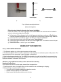
Electrode 1 23in (max) 23in (Max) Electrode 1 Electrode 2 Electrode 2 Horizontal Configuration Vertical Configuration a) b) Fig. 2: a) Electrode mounting behind the tub b) Electrode Configurations Follow the steps below for the water level sensor installation Locate the location for the sensor electrodes to be installed. Note: The electrodes can be installed in vertical or horizontal configuration (Fig. 2b) a) Drill two holes (3.5mm diameter) on the tub with approximate distance as shown in Fig. 2b above. Insert the electrodes and tighten the nuts to secure the ring connectors as shown in Fig. 2a above. b) Connect the other end of sensor cable to the BSC port named “Level Sensor” c) Connect the control button to the BSC port named “Control Button”. d) Connect the Light transformer to the BSC port named “Light” Note: The maximum current this port can provide is 1A. e) Connect the Blower to the BSC port named “Motor” WARRANTY INFORMATION One (1) YEAR LIMITED WARRANTY 1. This Warranty applies only to the original purchaser of this product. 2. This Warranty applies ONLY to repair or replacement of any supplied or manufactured parts of this product. The warranty does not cover normal wear, coating, dropped or abused unit. 3. Unless otherwise proscribed by law, The LURACO technologies, Inc. shall not be liable for any personal injury, property or any incidental or consequential damages of any kind resulting from malfunctions, defects, misuse, by improper installation or alteration of this product. Attention: Any modification to the product will void the warranty Important Instructions If you need to send a unit to us for repair, please follow the steps below. 1. Carefully pack the item in its original carton or other suitable box to avoid damage in shipping. 2. Before packing your unit; be sure to enclose: Your name with full shipping address and telephone number A dated receipt as PROOF OF PURCHASE Attach a paper detailing the problem you are having 3