1
YK200
USER MANUAL
020-100629-02
YK200
USER MANUAL
020-100629-02
NOTICES
COPYRIGHT AND TRADEMARKS
© 2012 Christie Digital Systems USA, Inc. All rights reserved.
All brand names and product names are trademarks, registered trademarks or trade names of their respective holders.
REGULATORY
The product has been tested and found to comply with the limits for a Class A digital device, pursuant to Part 15 of the FCC Rules.
These limits are designed to provide reasonable protection against harmful interference when the product is operated in a
commercial environment. The product generates, uses, and can radiate radio frequency energy and, if not installed and used in
accordance with the instruction manual, may cause harmful interference to radio communications. Operation of the product in a
residential area is likely to cause harmful interference in which case the user will be required to correct the interference at the
user’s own expense.
This Class A digital apparatus complies with Canadian ICES-003.
Cet appareil numérique de la classe A est conforme à la norme NMB-003 du Canada.
㧊 ₆₆⓪ 㠛ⶊ㣿 (A ) 㦒⪲ 㩚㧦䕢㩗䞿❇⪳㦚 䞲 ₆₆㧊㡺┞ 䕦ⰺ㧦 ⡦⓪ ㌂㣿㧦⓪ 㧊㩦㦚 㭒㦮䞮㔲₆ ⧒Ⳇ , Ṗ㩫 㣎㦮 㰖㡃㠦㍲
㌂㣿䞮⓪ ộ㦚 ⳿㩗㦒⪲ 䞿┞┺ .
GENERAL
Every effort has been made to ensure accuracy, however in some cases changes in the products or availability could occur which
may not be reflected in this document. Christie reserves the right to make changes to specifications at any time without notice.
Performance specifications are typical, but may vary depending on conditions beyond Christie's control such as maintenance of
the product in proper working conditions. Performance specifications are based on information available at the time of printing.
Christie makes no warranty of any kind with regard to this material, including, but not limited to, implied warranties of fitness for
a particular purpose. Christie will not be liable for errors contained herein or for incidental or consequential damages in
connection with the performance or use of this material.
The product is designed and manufactured with high-quality materials and components that can be recycled and reused. This
symbol
means that electrical and electronic equipment, at their end-of-life, should be disposed of separately from regular
waste. Please dispose of the product appropriately and according to local regulations. In the European Union, there are separate
collection systems for used electrical and electronic products. Please help us to conserve the environment we live in!
Canadian manufacturing facility is ISO 9001 and 14001 certified.
GENERAL WARRANTY STATEMENTS
For complete information about Christie’s limited warranty, please contact your Christie dealer. In addition to the other limitations
that may be specified in Christie’s limited warranty, the warranty does not cover:
a. Damage occurring during shipment, in either direction.
b. Projector lamps (See Christie’s separate lamp program policy).
c. Damage caused by use of a projector lamp beyond the recommended lamp life, or use of a lamp supplied by a supplier other
than Christie.
d. Problems caused by combination of the product with non-Christie equipment, such as distribution systems, cameras, video
tape recorders, etc., or use of the product with any non-Christie interface device.
e. Damage caused by misuse, improper power source, accident, fire, flood, lightening, earthquake or other natural disaster.
f. Damage caused by improper installation/alignment, or by product modification, if by other than a Christie authorized repair
service provider.
g. For LCD projectors, the warranty period specified applies only where the LCD projector is in “normal use.” “Normal use”
means the LCD projector is not used more than 8 hours a day, 5 days a week. For any LCD projector where “normal use” is
exceeded, warranty coverage under this warranty terminates after 6000 hours of operation.
h. Failure due to normal wear and tear.
PREVENTATIVE MAINTENANCE
Preventative maintenance is an important part of the continued and proper operation of your product. Please see the
Maintenance section for specific maintenance items as they relate to your product. Failure to perform maintenance as required,
and in accordance with the maintenance schedule specified by Christie, will void the warranty.
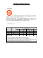
China RoHS Compliance Information
ޣҾѝഭ lj⭥ᆀؑӗ૱⊑ḃ᧗ࡦ㇑⨶࣎⌅NJⲴ䈤᰾
Environmentally Friendly Use Period
⧟⭘֯؍ᵏ䲀
The year number in the centre of the label indicates the Environmentally
Friendly Use Period, which is required to mark on the electronic information product sold
in China according to the China RoHS regulations.
ᵜḷᘇѝ㺘⽪Ⲵᒤᮠᱟṩᦞ lj⭥ᆀؑӗ૱⊑ḃ᧗ࡦ㇑⨶࣎⌅NJ˄2006 ᒤ 2 ᴸ 28
ᰕ˅ԕ৺ lj⭥ᆀؑӗ૱⊑ḃ᧗ࡦḷ䇶㾱≲NJ˄2006 ᒤ 11 ᴸ 6 ᰕ˅ࡦᇊⲴǃ䘲⭘
Ҿ൘ѝॾӪ≁઼ޡഭຳ䬰Ⲵ⭥ᆀؑӗ૱Ⲵ⧟⭘֯؍ᵏ䲀DŽ
Material Concentration Values Table
ᴹ∂ᴹᇣ⢙䍘ਜ਼䟿㺘
Material Concentration
( ᴹ∂ᴹᇣ⢙䍘ᡆݳ㍐ )
Part Name
䜘Ԧ〠
䫵
˄Pb˅
⊎
˄Hg˅
䭹
˄Cd˅
ޝԧ䬜
(Cr 6+˅
ཊⓤ㚄㤟
˄PBB˅
ཊⓤҼ㚄
㤟䟊
˄PBDE˅
X
O
O
O
O
O
⭥Ⓚ
Power supply
X
O
O
O
O
O
䘎᧕⭥㓯 㔶
Harness/cable
X
O
O
O
O
O
傜䗮
Motor
X
O
O
O
O
O
⭥䐟ᶯ
PCB
Mechanical
X
O
O
O
O
O
ᵪỠ䱴Ԧ
components*
Note:
O : indicates that the concentration value of the particular hazardous substance contained in all the homogeneous materials for this
part, according to EIP-A, EIP-B, EIP-C, is below the stipulated levels in China SJ/T11363-2006.
㺘⽪䈕ᴹ∂ᴹᇣ⢙䍘൘䈕䜘Ԧᡰᴹ൷䍘ᶀᯉѝⲴਜ਼䟿൷൘ SJ/T11363-2006 㿴ᇊⲴ䲀䟿㾱≲ԕлDŽ
X: indicates that the concentration value of the particular hazardous substance contained in all the homogeneous materials for this
part, according to EIP-A, EIP-B, EIP-C, may be above the stipulated levels in China SJ/T11363-2006.
㺘⽪䈕ᴹ∂ᴹᇣ⢙䍘㠣ቁ൘䈕䜘ԦⲴḀа൷䍘ᶀᯉѝⲴਜ਼䟿ਟ㜭䎵ࠪ SJ/T11363-2006 㿴ᇊⲴ䲀䟿㾱≲DŽ
* This part uses metallic alloys, which may contain Lead. ഐ䈕䜘Ԧ֯⭘䠁ਸ䠁ᶀᯉˈ᭵ਟ㜭ਜ਼ᴹ䫵DŽ
Table of Contents
1: Introduction
1.1 Labels and Marking .....................................................................................................................1-1
1.2 Typographical Notations .............................................................................................................1-1
1.3 General Features ..........................................................................................................................1-2
1.4 Input Rating .................................................................................................................................1-2
1.5 Safety Warnings ..........................................................................................................................1-2
1.5.1 Fuse Replacement ................................................................................................................1-3
1.6 Pre-operational Checklist ............................................................................................................1-3
2: Overview
2.1 YK200 Dual Arm Yoke...............................................................................................................2-1
2.1.1 YK200 Bracket ....................................................................................................................2-1
2.1.2 YK200 Dual Arm.................................................................................................................2-2
Removing the Yoke Arm Covers .......................................................................................2-2
2.1.3 YK200 Base.........................................................................................................................2-3
Removing the Base Covers ...................................................................................................2-4
Leg # 1: Display Module and Motherboard .........................................................................2-5
Leg # 2 Power-DMX Panel ..................................................................................................2-6
Leg # 3 Input Panel ...............................................................................................................2-7
2.2 YK200-Compatible Projectors ....................................................................................................2-7
2.2.1 Christie Roadster Series.......................................................................................................2-7
Modifications required .........................................................................................................2-7
2.3 Head Kits ....................................................................................................................................2-8
2.4 Rigging Accessories & Features..................................................................................................2-9
2.4.1 The Nitro Rigging Clamp ...................................................................................................2-9
2.4.2 Lifting Features....................................................................................................................2-10
Weights .................................................................................................................................2-10
3: Projector Installation
3.1 Roadster Series Lens Motor Replacement...................................................................................3-1
3.1.1 Lens Removal ......................................................................................................................3-1
3.1.2 Lens Motor Set Replacement...............................................................................................3-2
3.2 Roadster Series Bracket...............................................................................................................3-6
3.2.1 Bracket Description .............................................................................................................3-6
Quick Lock System ..............................................................................................................3-6
3.2.2 Bracket Setup.......................................................................................................................3-7
Removing the Bracket from the YK200 ..............................................................................3-7
Installing the Bracket on the YK200 ...................................................................................3-9
3.2.3 Installing the Roadster Series Projector on the Bracket ......................................................3-11
3.2.4 Lens Installation...................................................................................................................3-14
3.2.5 Balancing the Roadster Series Projector..............................................................................3-15
3.2.6 Making Electrical Connections............................................................................................3-18
YK200 User Manual
020-100629-02 Rev. 1 (08-2012)
i
Table of Contents
4: Operation
4.1 Pan and Tilt Movements ............................................................................................................. 4-1
4.1.1 Description .......................................................................................................................... 4-1
4.1.2 Locking System................................................................................................................... 4-1
4.2 Setup ........................................................................................................................................... 4-2
4.2.1 Opening and Ground Setup from a Flight Case .................................................................. 4-3
Description ........................................................................................................................... 4-3
Setup .................................................................................................................................... 4-3
4.2.2 System Power Up................................................................................................................ 4-7
Procedure ............................................................................................................................. 4-7
4.3 Truss Mounting........................................................................................................................... 4-10
4.3.1 Nitro Rigging Clamp Description ....................................................................................... 4-10
4.3.2 Rigging Procedure............................................................................................................... 4-11
4.4 DMX ........................................................................................................................................... 4-15
4.4.1 Controlling from a DMX Console or Controller ................................................................ 4-15
4.4.2 Control Panel....................................................................................................................... 4-15
Description ........................................................................................................................... 4-15
Roadster Series Menu .......................................................................................................... 4-16
Roadster Series DMX Protocol ............................................................................................ 4-22
5: Maintenance
5.1 Safety Warnings and Guidelines................................................................................................. 5-1
5.1.1 General Precautions ............................................................................................................ 5-1
5.2 Pre-Operational Checklist........................................................................................................... 5-1
5.3 Cleaning .................................................................................................................................... 5-2
5.3.1 Yoke .................................................................................................................................... 5-2
5.3.2 Projector .............................................................................................................................. 5-2
5.4 Lubrication.................................................................................................................................. 5-2
5.4.1 Chains ................................................................................................................................. 5-2
5.5 User-Serviceable Components.................................................................................................... 5-2
5.5.1 Yoke .................................................................................................................................... 5-2
Power Cable ......................................................................................................................... 5-2
Microchip ............................................................................................................................. 5-3
Fuses .................................................................................................................................... 5-3
Chain .................................................................................................................................... 5-3
5.5.2 Projector .............................................................................................................................. 5-4
6: Troubleshooting
6.1 Yoke............................................................................................................................................ 6-1
6.2 Projector...................................................................................................................................... 6-3
ii
YK200 User Manual
020-100629-02 Rev. 1 (08-2012)
Table of Contents
7: Specifications
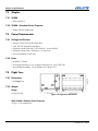
7.1 General Capabilities ....................................................................................................................7-1
7.1.1 Pan and Tilt Movements ......................................................................................................7-1
7.1.2 Focus Control.......................................................................................................................7-1
7.1.3 Zoom Control.......................................................................................................................7-1
7.2 Physical........................................................................................................................................7-1
7.2.1 Yoke Dimensions.................................................................................................................7-1
7.2.2 Yoke Body ...........................................................................................................................7-1
7.2.3 Mounting Options ................................................................................................................7-1
7.3 Weights ........................................................................................................................................7-2
7.3.1 YK200..................................................................................................................................7-2
7.3.2 YK200 + Roadster Series Projector.....................................................................................7-2
7.4 Power Requirements....................................................................................................................7-2
7.4.1 Voltage and Current.............................................................................................................7-2
7.4.2 Fuses ....................................................................................................................................7-2
7.5 Flight Case ...................................................................................................................................7-2
7.5.1 Dimensions ..........................................................................................................................7-2
7.5.2 Weight..................................................................................................................................7-2
Empty ....................................................................................................................................7-2
With YK200 + Roadster Series Projector .............................................................................7-2
7.6 Regulatory ...................................................................................................................................7-3
7.7 Environment ................................................................................................................................7-3
7.8 Optional Components ..................................................................................................................7-3
YK200 User Manual
020-100629-02 Rev. 1 (08-2012)
iii
1 Introduction
The Christie Nitro YK200 is an automated yoke designed exclusively for technicians with expertise in DMX
technology and high power automated projectors.
You must read this document in its entirety to ensure the Christie Nitro YK200 is installed and operated
correctly. Failure to follow the instructions in this manual could result in personal injury or damage to the
projector or the Christie Nitro YK200.
This product is also designed for temporary outdoor use, but must remain dry under all circumstances.
Servicing of this product may only be performed by Christie accredited service technicians.
1.1
Labels and Marking
Observe and follow any warnings and instructions marked on the Christie Nitro YK200 and throughout this
manual:
Danger symbols indicate a hazardous situation which, if not avoided, will result in death
or serious injury.
Warning symbols indicate a hazardous situation which, if not avoided, could result in
death or serious injury.
Caution symbols indicate a hazardous situation which, if not avoided, could result in
minor or moderate injury.
NOTICE! Addresses practices not related to personal injury.
1.2
Typographical Notations
The following notations are used throughout this manual:
• Keypad commands and computer keystrokes appear in bold small caps, such as POWER, INPUT, ENTER etc.
• References to specific areas of the document appear italicized and underlined. When viewed online the text
appears in blue indicating a direct link to that section. For example, Section 1 Introduction.
• References to other documents appear italicized and bold, such as User Manual.
• References to software menus and available options appear bold, such as Main menu,
Preferences.
• User input or messages that appear on screen, in status display units or other control modules appear in
Courier font. For example. “No Signal Present”, Login: christiedigital.
• Error codes, LED status appear in bold, e.g. LP, A1 etc.
• Operational states of modules appear capitalized, such as power ON/OFF.
YK200 User Manual
020-100629-02 Rev. 1 (08-2012)
1-1
Section 1: Introduction
1.3
General Features
The Christie Nitro YK200 is controlled by a DMX interface and offers these automated functions:
•
•
•
•
1.4
600° pan powered by DC servo motor – 16 bits,
270° tilt powered by DC servo motor – 16 bits,
Focus powered by DC servo motors – 8 bits
Zoom powered by DC servo motors – 8 bits
Input Rating
Table 1.1 Operating Power
1.5
Zone
Voltage
Connection
Operating Current
EUROPE
230VAC 50HZ
32A SINGLE-PHASE + EARTH GROUND
(YOKE ONLY)
1A
USA
208VAC 60HZ
30A DUAL-PHASE + EARTH GROUND
(YOKE ONLY)
1.8 A
ALL
200-240 VAC 50/60HZ
YOKE + PROJECTOR
23 A
Safety Warnings
All servicing must be performed by CHRISTIE accredited service technicians.
Use replacement parts that are manufacturer-approved only. Use of any other part other than
the ones specified by the manufacturer can result in fire, electric shock or risk of personal
injury and irreparable equipment damage.
For protection from electric shock, the YK200 must be grounded (earthed) to
protect against electrical shock and the AC power distribution circuit must be equipped with
a fuse or circuit breaker and ground-fault (earth-fault) protection.
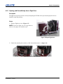
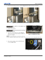
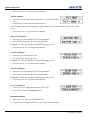
Disconnect the YK200 from AC power before removing any cover or part –
including fuses – and when not in use (See Figure 1-1 and Figure 1-2). Covers shall only be
removed by CHRISTIE accredited service technicians.
Isolate the YK200 from power immediately if any power connector, power
cable, seal, cover or other component is damaged, defective, deformed, wet or showing signs
of overheating. Do not reconnect power until repairs have been completed and unit is
completely dry.
Do not expose the YK200 to rain or moisture.
This symbol appears in this manual for procedures where a Pinching or Crushing
hazard between chain and sprocket exists. Keep hands clear when unit is
powered. Disconnect power before servicing.
1-2
YK200 User Manual
020-100629-02 Rev. 1 (08-2012)
Section 1: Introduction
This symbol appears in this manual for procedures where a Pinching or Crushing
hazard between rotating and stationary surfaces exists. Keep hands clear when
unit is powered. Disconnect power before servicing or apply rotation locks.
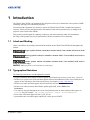
Figure 1-1 Power Cable Connector - Slide
Metal Release Tab and Unlock
Figure 1-2 Power Cable Connector - Remove
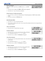
1.5.1 Fuse Replacement
Disconnect the YK200 from power before replacing a fuse. Replace fuses with
ones of the same type and rating. Never bypass or bridge a fuse. Covers shall only be
removed by CHRISTIE accredited service technicians.
The YK200 head box is protected by one fuse located next to the power switch. Use the correct replacement
fuse for the zone in which it operates:
• T750mA for 200-240V
There are also 2 fuses inside one of the legs of the base:
• T1.6A (250V) located on the power supply board (Conquer Electronics Co., Ltd # UTE1.60)
• T6.3A time delay (250V) located in an inline fuse holder (Schurter AG # 0034.3125)
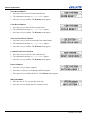
1.6
Pre-operational Checklist
Before you operate the Christie Nitro YK200, check these items:
• Verify that the power cable connector is locked to the yoke base.
• Verify that the green LED is flashing on the control panel. This indicates that the yoke is receiving a DMX
signal.
• Verify that the connection between the projector and the yoke is correct.
• Verify that the yoke and projector lens will not collide with other objects.
• Verify that the pan and tilt functions on the yoke are unlocked. See 4.1.2 Locking System, on page 4-1.
• Verify that the Nitro Rigging Clamps are installed securely. See 4.3 Truss Mounting, on page 4-10.
• Verify that the Quick Lock is locked and secured. See Quick Lock System, on page 3-6.
YK200 User Manual
020-100629-02 Rev. 1 (08-2012)
1-3
Section 1: Introduction
•
•
•
•
Verify that the screws on the dual bracket are tight after balancing the projector.
Verify that the lens is properly mounted and locked after replacing zoom and focus motors.
Verify that the yoke is properly grounded.
Verify that the AC power complies with the local building and electrical codes and has both overload and
ground-fault (earth-fault) protection.
• Verify that all power distribution equipment and cables are in good condition and rated for the requirements
of the connected devices.
• Verify that the DMX distribution has XLR 5 pin connectors. See Figure 4-17 DMX In and Thru XLR Connectors, on page 4-8.
1-4
YK200 User Manual
020-100629-02 Rev. 1 (08-2012)
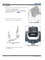
2 Overview
2.1
YK200 Dual Arm Yoke
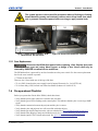
The YK200 is comprised
of the following main
components (Figure 2-1):
• The dual arm (1)
• The base, referred to as
TopBox or Tripod (2)
• Handles (3)
• Quick Locks (4)
Figure 2-1 YK200 Components
2.1.1 YK200 Bracket
The YK200 bracket
assembly contains these
components (Figure 2-2):
• The platform (1), which
accepts adaptor plates
that are unique to each
projector series.
• A head box (2), which
provides a location for
projector connections.
Figure 2-2 Bracket Platform and Head Box
YK200 User Manual
020-100629-02 Rev. 1 (08-2012)
2-1
Section 2: Overview
2.1.2 YK200 Dual Arm
The YK200 dual arm contains these components:
•
•
•
•
•
Sub connection panel
Pan and tilt motors
Tilt Sensor
Pan axis
Pan and tilt chain stretchers
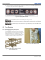
Removing the Yoke Arm Covers
Figure 2-3 YK200 Dual Arm
All servicing must be performed by CHRISTIE
accredited service technicians. Use replacement parts that are
manufacturer-approved only. Use of any other part other than
the ones specified by the manufacturer can result in fire,
electric shock or risk of personal injury and irreparable
equipment damage.
1. Remove 6 screws from the vertical covers on both ends of the arm as
shown in Figure 2-4. This provides access to the components in
Figure 2-5.
The covers should always be in place and
secured before switching projector power to ON.
Figure 2-4 Vertical Cover
Removal
2-2
YK200 User Manual
020-100629-02 Rev. 1 (08-2012)
Section 2: Overview
Figure 2-5 Vertical Components
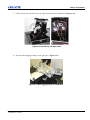
2. Remove screws from the 3 horizontal covers shown in Figure 2-3 to access the components in Figure 2-6.
Figure 2-6 Horizontal Components
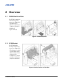
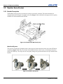
2.1.3 YK200 Base
The YK200 base is also called Top Box or Tripod. The base (Figure 2-7) contains these components, each
protected by an ABS cover and fitted with one handle:
• Display Module and Motherboard
• Power and DMX Connectors
• Video Connectors
The covers should always be in place and secured before switching projector
power to ON.
YK200 User Manual
020-100629-02 Rev. 1 (08-2012)
2-3
Section 2: Overview
Figure 2-7 YK200 Base with and without Covers
All servicing must be performed by CHRISTIE accredited service technicians.
Use replacement parts that are manufacturer-approved only. Use of any other part other than
the ones specified by the manufacturer can result in fire, electric shock or risk of personal
injury and irreparable equipment damage.
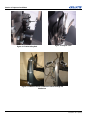
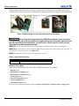
Removing the Base Covers
To remove the base covers (Figure 2-8):
1. Remove the 4 screws (2 on each side) securing the handle to the base frame.
2. Lift the handle from the base cover.
3. Lift the cover from the base frame.
Figure 2-8 Remove Base Handle and Cover
2-4
YK200 User Manual
020-100629-02 Rev. 1 (08-2012)
Section 2: Overview
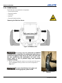
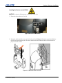
Leg # 1: Display Module and Motherboard
From this panel, you have access to all the projector functions. This part also contains the Motherboard.
Figure 2-9 LCD Display
Figure 2-10 Motherboard CPU - Top View
Disconnect the YK200 Yoke from AC power before removing any cover or part,
including fuses – and when not in use. Covers shall only be removed by CHRISTIE accredited
service technicians.
Motherboard (CPU) Features
Figure 2-11 Motherboard Features
YK200 User Manual
020-100629-02 Rev. 1 (08-2012)
2-5
Section 2: Overview
NOTE: The DIP switches in Figure 2-11 do not affect projector operation.
Leg # 2 Power-DMX Panel
The Power-DMX panel includes these components (Figure 2-12):
• Power switch
• PowerCon connector
• DMX in and out
This Leg also houses a transformer (arrow in Figure 2-13) that powers the Motherboard (CPU) as well as Pan
and Tilt yoke motors.
Figure 2-12 Power-DMX Panel
Figure 2-13 Leg #2 Top View
Disconnect the YK200 Yoke from AC power before removing any cover or part
including fuses – and when not in use. Covers shall only be removed by CHRISTIE accredited
service technicians.
Table 2.1 Fuse Values
Description
POWER SUPPLY TRANSFORMER (150
VA)
2-6
Voltage Range
Fuse protection
PRIMARY
208-230 V
T1.6A (250V) - USE ONLY CONQUER
ELECTRONICS CO., LTD # UTE1.60)
SECONDARY
22 V
T6.3A (250V) - USE ONLY
SCHURTER AG # 0034.3125
YK200 User Manual
020-100629-02 Rev. 1 (08-2012)
Section 2: Overview
Leg # 3 Input Panel
This panel includes these ports (Figure 2-14):
• 1 - Ethernet Input
• 2 - DVI-I type input
Figure 2-14 Input Panel
2.2
Figure 2-15 Leg#3 Top View
YK200-Compatible Projectors
2.2.1 Christie Roadster Series
The Christie Roadster Series video projector can be mounted to the YK200 with a special bracket. A minor
modification is required to interface with the YK200, but all other Roadster features and functions are
unchanged. Refer to the Roadster Series manuals for more information.
Figure 2-16 Roadster Series Front View
Figure 2-17 Roadster Series Connection Panel
Modifications required
Zoom and focus motors on the Roadster lens must be replaced with YK200 motors. You use the DMX protocol
to control these motors.
YK200 User Manual
020-100629-02 Rev. 1 (08-2012)
2-7
Section 2: Overview
2.3
Head Kits
Projectors are mounted to the yoke using a Head Kit comprised of:
• The YK200 bracket (Figure 2-18) and
• Adaptor plates specific to the projector series. (Figure 2-19)
The bracket has a Quick Lock (see page 3-6), allowing simplified
installation and removal.
One type of Heads Kit is available for the YK200:
• Roadster Series adaptor plates. (Figure 2-19)
Figure 2-18 YK200 Bracket
Figure 2-19 Roadster Head Kit Adaptor
Plates
Figure 2-20 YK200 with Roadster
A typical projector configuration using the YK200 is
shown in Figure 2-20.
2-8
YK200 User Manual
020-100629-02 Rev. 1 (08-2012)
Section 2: Overview
2.4
Rigging Accessories & Features
2.4.1 The Nitro Rigging Clamp
The Nitro Rigging Clamp (P/N 131-109101-xx) is an optional accessory that provides a means for attaching
the YK200 to a truss.
The Nitro Rigging Clamp (Figure 2-21) is designed to allow the YK200 base to be mounted either on the top
or the bottom of a truss (Figure 2-22). Its adjustable clamps permit the Nitro Rigging Clamp to accommodate
trusses of different widths.
Figure 2-21 Nitro Rigging Clamp with its 4
adjustable clamps
Figure 2-22 Nitro Rigging Clamp mounted
on top and bottom of truss
One triangular plate (Figure 2-23) is directly fitted on the Pan axis, under the YK200 Tripod. This plate is
designed to engage with the Nitro Rigging Clamp hook. One removable safety ring is also integrated with the
bottom of the base to allow the projector to be secured with a safety cable (Figure 2-24).
Figure 2-23 Triangular Plate
YK200 User Manual
020-100629-02 Rev. 1 (08-2012)
Figure 2-24 Base Safety Ring
2-9
Section 2: Overview
2.4.2 Lifting Features
An inbox lifting ring is fitted on top of each arm. It allows the YK200 to be lifted for easy maintenance or for
an installation away from its flight case.
Lifting of the YK200 must only be performed by a trained professional.
The YK200 tilts slightly when extracted from its flight case.
Figure 2-25 Lifting Ring
Figure 2-26 Lifting Ring suspending
YK200
Weights
Verify your lifting equipment has an adequate weight rating to lift the yoke:
• YK200 and Roadster Series w/o lens: 200 kg (441 lbs)
2-10
YK200 User Manual
020-100629-02 Rev. 1 (08-2012)
Section 3: Projector Installation
3 Projector Installation
3.1
Roadster Series Lens Motor Replacement
To implement lens zoom and focus control from the DMX console, it will be necessary to replace the Roadster
lens motors.
Do not touch or remove any parts except those that are documented in the procedure.
Malfunctions, electrical shock, fire hazard or other accidents may result.
NOTICE! When moving or setting up a projector, ensure the lens cap is in place to prevent damage to the lens
surface. Do not subject the lens to force and do not lift the projector by the lens. The actions can result in
damage to the lens, cabinet or mechanical components.
3.1.1 Lens Removal
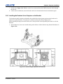
1. Install the front lens cap. (Figure 3-1)
2. Press the lens button. (Figure 3-1)
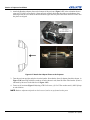
3. Rotate the lens counter-clockwise until the tabs are free of the retaining ring (Figure 3-2 A). Pull lens out
(Figure 3-2 B). Lens connectors will disconnect when the lens is pulled straight out.
NOTICE! The connector slide assembly allows the connector to move as the lens is rotated.
Figure 3-1 Lens Cap Placement
YK200 User Manual
020-100629-02 Rev. 1 (08-2012)
Figure 3-2 Lens Removal
3-1
Section 3: Projector Installation
3.1.2 Lens Motor Set Replacement
NOTICE! All original screws must be set aside for reuse.
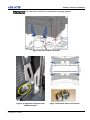
1. Remove lens motor cover by removing screws
shown in Figure 3-3.
2. Remove the motor set from the lens by removing the
screws in Figure 3-4.
Figure 3-3 Motor Cover Removal
Figure 3-4 Motor Set Removal
3. Remove the connector bracket. (Figure 3-5)
Figure 3-5 Connector Removal
3-2
YK200 User Manual
020-100629-02 Rev. 1 (08-2012)
Section 3: Projector Installation
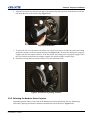
4. Open the replacement motor set. (Figure 3-7)
Figure 3-7 Open Replacement Motor Set
Figure 3-6 Replacement Motor Set
5. Loosen the screws at the locations shown in Figure 3-8 to unlock the motor position adjustments.
Figure 3-8 Unlock Motor Adjustments
6. Place the lens in the motor set in the orientation shown in Figure 3-9.
YK200 User Manual
020-100629-02 Rev. 1 (08-2012)
3-3
Section 3: Projector Installation
Figure 3-9 Place Lens in Motor Set
7. Close the motor set arms and fasten them with the hardware shown in Figure 3-10.
Figure 3-10 Fasten Motor Arms
3-4
YK200 User Manual
020-100629-02 Rev. 1 (08-2012)
Section 3: Projector Installation
8. Allow the motor gears to mesh with the lens gears. (Figure 3-11)
NOTICE! DO NOT apply additional pressure on the gears in an effort to mesh them.
Figure 3-11 Engage Gears
9. Inspect the motor gears to ensure they are meshed with
the lens gears. Tighten the motor position adjustment
screws loosened earlier (Refer back to Figure 3-8).
10. Carefully rotate the lens gears and verify that the motor
gears are rotating. If gear operation is satisfactory, the
lens is ready for installation.
Figure 3-12 Lens with Replacement Motors
YK200 User Manual
020-100629-02 Rev. 1 (08-2012)
3-5
Section 3: Projector Installation
3.2
Roadster Series Bracket
3.2.1 Bracket Description
The Roadster Series projector is mounted on a unique video head, or bracket. The bracket includes two
triangular plates that form part of a Quick Lock system (Figure 3-13), which allows the projector to be quickly
mounted on or dismounted from the YK200.
Figure 3-13 Bracket with Quick Lock plate
Quick Lock System
This system is comprised of triangular plates on the projector bracket that mate with a slots on the YK200 tilt
mechanism (Figure 3-14). They are secured with a latch that fastens with (2) nuts, (3) blocking bolts and (1)
safety bolt. With only a few steps, the user can quickly change out projectors that have been pre-mounted onto
brackets.
Figure 3-14 Quick Lock System
3-6
YK200 User Manual
020-100629-02 Rev. 1 (08-2012)
Section 3: Projector Installation
3.2.2 Bracket Setup
All servicing must be performed by CHRISTIE accredited service technicians.
Use replacement parts that are manufacturer-approved only. Use of any other part other than
the ones specified by the manufacturer can result in fire, electric shock or risk of personal
injury and irreparable equipment damage.
Removing the Bracket from the YK200
On occasion, it may be necessary to remove the bracket from the YK200. Perform the following steps on both
sides of the bracket:
1. Lock the tilt axis, then loosen (2) M8 latch nuts (Figure 3-15).
2. Back off the (3) TH 6x16 blocking bolts (Figure 3-16).
Figure 3-15 Undo 2 Latch Nuts
Figure 3-16 Undo 3 Blocking Bolts
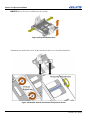
3. Back off the safety bolt (Figure 3-17).
4. Open the latch (Figure 3-18).
5. Remove the yoke arm cover (6 screws) and pull the cables through the tilt axis opening (Figure 3-19).
6. Lift the bracket from the YK200.
YK200 User Manual
020-100629-02 Rev. 1 (08-2012)
3-7
Section 3: Projector Installation
Figure 3-17 Undo Safety Bolt
Figure 3-18 Open Latch
Figure 3-19 Remove Covers and Extract Cables through Tilt
Mechanism
3-8
YK200 User Manual
020-100629-02 Rev. 1 (08-2012)
Section 3: Projector Installation
Installing the Bracket on the YK200
NOTICE! Perform the following steps on both sides of the yoke.
1. Ensure the tilt mechanism is locked.
Figure 3-20 Lock Tilt Mechanism
2. Rotate the bracket until the arrow on the bracket (circled in Figure 3-21) points upward and slide the
Quick Lock plates into the yoke. The arrow on the bracket also indicates where the lens end of the
projector will be located.
Figure 3-21 Mount Bracket onto Yoke
YK200 User Manual
020-100629-02 Rev. 1 (08-2012)
3-9
Section 3: Projector Installation
NOTICE! There are 2 ways that the bracket can be oriented when mounting onto the yoke. The correct
orientation is with the right side of the projector (as viewed from lens end) closest to yoke Arm#1, which
contains the sub connection panel. The upward arrow on the bracket also indicates the correct orientation.
3. Close the latch. (Figure 3-22)
4. Tighten the safety bolt. (Figure 3-23)
Figure 3-23 Tighten Safety
Bolt
Figure 3-22 Close Latch
5. Tighten (3) blocking bolts. (Figure 3-24)
6. Tighten (2) latch nuts. (Figure 3-25)
Figure 3-24 Tighten Blocking Bolts
Figure 3-25 Tighten Latch Nuts
3-10
YK200 User Manual
020-100629-02 Rev. 1 (08-2012)
Section 3: Projector Installation
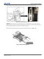
7. Refer back to Figure 3-19. With the vertical cover removed, thread the DMX and power cables through
the tilt axis.
8. Unlock the tilt mechanism, rotate the bracket until it is horizontal and lock the tilt mechanism again.
3.2.3 Installing the Roadster Series Projector on the Bracket
The bracket assembly includes an adjustable plate which allows the projector position on the bracket to be
adjusted for optimum balance. The projector is mounted to this plate with (2) adaptor plates.
Before mounting the projector on the bracket, the vertical position of the adjustable plate must be set for the
Roadster.
1. Ensure that the (6) screws are located starting at the third set of holes from the top (bottom illustrations in
Figure 3-26).
Figure 3-26 Vertical Height Adjustment for Roadster
YK200 User Manual
020-100629-02 Rev. 1 (08-2012)
3-11
Section 3: Projector Installation
2. Attach the Roadster adaptor plates to the bottom of the projector (Figure 3-27) in the orientation shown
using (4) TH 12x25 screws and (4) 12mm split lock washers. Note that the notch on each adaptor plate
must align with the screw heads as shown at bottom right. Slide the plates then fasten the M12 screws once
the plates are aligned.
Figure 3-27 Attach the Adaptor Plates to the Projector
3. Turn the projector upright, and place it on the bracket. Note that the front (2) adaptor plate holes shown, in
Figure 3-28, must align with the second set of holes (shown in red) from the front of the bracket. (Front is
indicated by the arrow in the blue box in Figure 3-28).
4. Fasten at (4) locations (Figure 3-30) using a TH12x30 screw, (2) 12x27 flat washers and (1) M12 Nylstop
at each location.
NOTE: Balance adjustment depends on the lens used, and is not performed at this point.
3-12
YK200 User Manual
020-100629-02 Rev. 1 (08-2012)
Section 3: Projector Installation
Ensure that the tilt mechanism is locked before mounting projector.
Figure 3-28 Place Projector on Bracket
Figure 3-29 Alignment of Adaptor Plates
with Bracket Holes
YK200 User Manual
020-100629-02 Rev. 1 (08-2012)
Figure 3-30 Fastener Details and Locations
3-13
Section 3: Projector Installation
5. Install the Head Box as shown in Figure 3-31 using (2) TH 6x16 screws, (1) 6x18 flat washer and (1) split
lockwasher on each side.
Figure 3-31 Fasten Head Box to Bracket
3.2.4 Lens Installation
1. Connect the lens connector to the external zoom and focus cable from the Head Box. (Figure 3-32)
Figure 3-32 Lens Connection to Zoom and Focus Cable
NOTICE! Before lens installation, remove rear lens cap.
3-14
YK200 User Manual
020-100629-02 Rev. 1 (08-2012)
Section 3: Projector Installation
2. Align the tabs on the lens with the slots in the lens retainer ring on the projector. Push the lens in until the
tabs touch the back of the retainer ring. (Figure 3-33)
Figure 3-33 Install Lens
3. To ensure the lens is secured in the lens mount, turn it clockwise until you feel the tabs on the lens butting
against the end stops on the lens mount retaining ring (Figure 3-34). To ensure the locking pin is properly
engaged, turn the lens counter-clockwise. If the lens rotates, the locking pin is not properly engaged. Turn
the lens clockwise and pull the lens plunger assembly out until the plunger assembly stops.
4. Recheck by turning the lens counter-clockwise.The lens should not rotate.
Figure 3-34 Lock Lens by turning clockwise
3.2.5 Balancing the Roadster Series Projector
Depending upon the choice of lens used on the Roadster, the balance adjustment will vary. Balancing is
achieved by adjusting the bracket in both the horizontal and vertical directions. (Figure 3-35)
YK200 User Manual
020-100629-02 Rev. 1 (08-2012)
3-15
Section 3: Projector Installation
NOTICE! Ensure the lens is installed before proceeding.
Figure 3-35 Bracket Balance Axes
Adjustments are made with 2 screws for the vertical axis and 1 screw for the horizontal axis.
Figure 3-36 Bracket Vertical and Horizontal Adjustment Screws
3-16
YK200 User Manual
020-100629-02 Rev. 1 (08-2012)
Section 3: Projector Installation
When adjusting the bracket height, use the scales to ensure all bolts are set to the same value.
Figure 3-37 Vertical Adjustment Scales
NOTICE! With the YK200 power turned off and the tilt axis unlocked, balance is only achieved when the
projector does not tilt on its own when set to tilt angles of 0°, 45° and 90°. As a result, it may be necessary to
perform the balance adjustment more than once until this is achieved.
When all balance adjustments have been completed, lock all 8 blocking screws. (Figure 3-38)
Figure 3-38 Balance Blocking Screws
YK200 User Manual
020-100629-02 Rev. 1 (08-2012)
3-17
Section 3: Projector Installation
3.2.6 Making Electrical Connections
All servicing must be performed by CHRISTIE accredited service technicians.
Use replacement parts that are manufacturer-approved only. Use of any other part other than
the ones specified by the manufacturer can result in fire, electric shock or risk of personal
injury and irreparable equipment damage.
1. Remove the yoke arm cover on Arm #1, which contains the sub
connection panel (6 screws). See Figure 3-39.
2. Connect the Roadster AC cable to the sub connection panel as shown in
Figure 3-40.
Figure 3-39 Remove Yoke
Arm Cover
Figure 3-40 Roadster AC Connection to Yoke
3-18
YK200 User Manual
020-100629-02 Rev. 1 (08-2012)
Section 3: Projector Installation
3. Attach the DMX Data In cable and the Power Supply cable to
the sub connection panel (circled in Figure 3-41).
4. Route the Power In and DMX Data In cables to the Head Box
as shown in Figure 3-42. Make connections to the Head Box
(Figure 3-43). The Power In connector must be locked by
turning the shell clockwise.
Figure 3-41 Head Box Connections
to Sub Connection Panel
Figure 3-42 Head Box to Yoke Routing
Figure 3-43 Head Box Connections
YK200 User Manual
020-100629-02 Rev. 1 (08-2012)
3-19
Section 3: Projector Installation
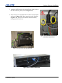
5. Make the RS232 and DVI connections as shown in Figure 3-44. Ensure that the RS232 cable is plugged
into the RS232 OUT connector.
Figure 3-44 Roadster Projector Connections
6. Remove the Head Box cover. The location of the zoom and focus board is highlighted in Figure 3-45.
Figure 3-45 Head Box Cover Removal and Zoom and Focus Board Location
3-20
YK200 User Manual
020-100629-02 Rev. 1 (08-2012)
Section 3: Projector Installation
7. Ensure that the grey coding wheel (arrow in Figure 346) on the Zoom and Focus board is set to “1” and that
the DIP switches (circled in Figure 3-46) are set as
shown (switch #1 OFF, switch #2 OFF).
NOTICE! Head Box power must be OFF before changing
the address with the grey coding wheel. Failing to do so
may produce destructive or disruptive effects.
8. Locate the DMX/RS232 board in the Head Box
(highlighted in Figure 3-47).
Figure 3-46 Zoom and Focus Grey Coding
Wheel
Figure 3-47 DMX/RS232 Board Location in Head Box
YK200 User Manual
020-100629-02 Rev. 1 (08-2012)
3-21
Section 3: Projector Installation
9. Figure 3-48 shows the DMX/RS232 board detail. For the Roadster Series, ensure that a jumper is not
present on the pins highlighted in red.
Figure 3-48 DMX/RS232 Board Detail
10. Install Head Box cover.
3-22
YK200 User Manual
020-100629-02 Rev. 1 (08-2012)
4 Operation
This section provides information and procedures for operating the Christie Nitro YK200 yoke.
4.1
Pan and Tilt Movements
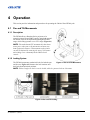
4.1.1 Description
The YK200 allows a Roadster Series projector to be
remotely oriented from a DMX console, using both pan and
tilt motion. Pans can be implemented through a full 600°
range, while tilting operates over a 270° range. (Figure 4-1)
NOTE: The motherboard CPU automatically shuts down
motor power when pan or tilt movements encounter any
kind of physical resistance. This automatic safety feature
can only be defeated by removing the source of resistance
and sending a new command from the DMX control
console.
4.1.2 Locking System
The YK200 incorporates mechanical locks for both the pan
and tilt axes. Figure 4-2 illustrates the lock locations and
their locked and unlocked positions.
Figure 4-1 Pan and Tilt Movements
NOTE: Tilt has 2 angles at which it can be locked, while the pan axis locks at 3 locations.
Figure 4-2 Pan and Tilt Locking
YK200 User Manual
020-100629-02 Rev. 1 (08-2012)
4-1
Section 4: Operation
The 3 pan lock positions are shown in Figure 4-3. Note that the tripod is in exactly the same orientation in each
case.
Figure 4-3 Pan Lock Positions
Tilt locking can be used to facilitate handling or maintenance (ie. bracket removal).
NOTICE! Before switching on the projector, verify that the 3 locking bars are in the unlocked position. This is
required to allow the projector to reset. The YK200 will not respond to DMX commands when locked.
4.2
Setup
This procedure applies to the YK200 equipped with a Roadster Series projector.
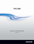
The stability of the YK200 base should always be checked and the strength of the platform needed to support it
should never be underestimated. The momentum generated by pan and tilt movements should also be taken
into account. The average surface area of the platform needed is 1.70m x 1.70m. The footprint of the YK200
without projector is shown in Figure 4-4.
Figure 4-4 YK200 Dimensions (mm)
4-2
YK200 User Manual
020-100629-02 Rev. 1 (08-2012)
Section 4: Operation
4.2.1 Opening and Ground Setup from a Flight Case
Description
The flight case provides a means of safely transporting the YK200 with a pre-mounted projector. It also
simplifies setup and packing.
Setup
1. Remove flight case cover. (Figure 4-5)
NOTE: To move the flight case over long distances,
wheels on the flight case should be used.
Figure 4-5 Open Flight Case
2. Unlock the retention plate (2 places), slide it down then remove it. (Figure 4-6)
Figure 4-6 Remove Retention Plate
YK200 User Manual
020-100629-02 Rev. 1 (08-2012)
4-3
Section 4: Operation
3. Lock the tilt axis (2 places) on the
YK200. (Figure 4-7)
Figure 4-7 Lock Tilt Axis on YK200
4. Tilt the flight case base up. (Figure
4-8)
Figure 4-8 Tilt Flight Case Base Up
4-4
YK200 User Manual
020-100629-02 Rev. 1 (08-2012)
Section 4: Operation
5. Undo latches on flight case and separate the base. (Figure 4-9)
Figure 4-9 Remove Flight Case Base
6. Tilt the flight case up until the yoke tripod touches the ground.
Figure 4-10 Tilt Flight Case Up
YK200 User Manual
020-100629-02 Rev. 1 (08-2012)
4-5
Section 4: Operation
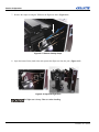
7. Remove the straps securing the YK200 to the flight case base. (Figure 4-11)
Figure 4-11 Remove Security Straps
8. Open the internal locks (both sides) and separate the flight case from the yoke. (Figure 4-12)
Figure 4-12 Separate Flight Case
The flight case is heavy. Take care when handling.
4-6
YK200 User Manual
020-100629-02 Rev. 1 (08-2012)
Section 4: Operation
4.2.2 System Power Up
NOTICE! Before switching on the YK200, verify that the 3 locking bars (2 tilt and 1 pan) are in the unlocked
position. This is required to allow the YK200 to reset.
In order to disconnect both yoke and projector from the power source in an
emergency, it will be necessary to pull the power plug from the power source
receptacle.
Procedure
1. Complete this checklist:
• Verify that power is available near the YK200 installation location
• Verify that ground fault protection is functioning
• Verify that power cables are undamaged
• Verify that the YK200 power switch is in the OFF position
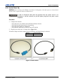
2. Plug the power cable into a 32 Amp socket. (Figure 4-13)
The mains voltage used in the country where the YK200 is used should always be checked:
Europe
230V Single Phase
North America
208V Dual Phase
Figure 4-13 Power Cables
YK200 User Manual
020-100629-02 Rev. 1 (08-2012)
4-7
Section 4: Operation
3. Attach the power cable to the YK200 (Figure 4-14) and lock the connector (Figure 4-15).
Figure 4-14 Attaching Power Cable
Figure 4-15 Locking Power Cable
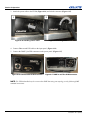
4. Connect Ethernet and DVI cables to the input panel. (Figure 4-16)
5. Connect the DMX 5 pin XLR connectors to the power panel. (Figure 4-17)
Figure 4-16 Connect Ethernet RJ45 and DVI-I
Figure 4-17 DMX In and Thru XLR Connectors
NOTE: The YK200 should always be connected to DMX data using star topology, strictly following DMX
standard instructions.
4-8
YK200 User Manual
020-100629-02 Rev. 1 (08-2012)
Section 4: Operation
6. Ensure both tilt locking systems are unlocked (Figure 4-18) and that the pan lock is unlocked.
Figure 4-18 Tilt locked (left panel) and unlocked (right panel)
Never switch on the projector and
yoke at the same time.
7. Switch on the projector.
Always ensure personnel are not close
to the YK200 at startup.
8. Turn on the main YK200 power switch (Figure 419). The unit will start its pan and tilt reset. Wait for
the reset to complete.
Figure 4-19 YK200 Power Switch
NOTE: The main YK200 power switch only switches on
the yoke components (motors and electronic boards). The projector power switch is independent of the yoke.
9. Once reset is complete, switch on Head Box power
(circled in Figure 4-20).
Figure 4-20 Head Box Power Switch
YK200 User Manual
020-100629-02 Rev. 1 (08-2012)
4-9
Section 4: Operation
10. Check the LCD Panel on both the Head Box and the Tripod. In both places, both dmx and power LEDs on
the Display LCD panel should be lit. (Figure 4-21)
Figure 4-21 Display LCD Panel LEDs
NOTE: A green flashing dmx LED indicates that a DMX signal is being received.
Always wait until the reset process is complete before switching on the next YK200 and
projector system.
There should always be two technicians at every YK200 startup: one at the DMX console
and one at the yoke
4.3
Truss Mounting
4.3.1 Nitro Rigging Clamp Description
The Nitro Rigging Clamp hook was specially designed
for the YK200 system. It can be fixed on or under trusses
ranging from 300mm (11.8”) to 500mm (19.7”) wide
with 50mm(2”) section tubes. The Nitro Rigging Clamp
is designed to support a weight of 500 Kg (1102 lbs).
Figure 4-22 The Nitro Rigging Clamp
Figure 4-23 Nitro Rigging Clamps mounted
above and below a truss
4-10
YK200 User Manual
020-100629-02 Rev. 1 (08-2012)
Section 4: Operation
4.3.2 Rigging Procedure
1. Remove flight case cover and locate yoke below truss.
(Figure 4-24)
NOTE: To move the flight case over long distances,
wheels on the flight case should be used.
Figure 4-24 Open Flight Case
2. Unlock the retention plate (2 places), slide it down
then remove it. (Figure 4-25)
Figure 4-25 Remove Retention Plate
3. Lock the tilt axis (2 places) on the
YK200. (Figure 4-26)
Figure 4-26 Lock Tilt Axis on YK200
YK200 User Manual
020-100629-02 Rev. 1 (08-2012)
4-11
Section 4: Operation
4. Tilt the flight case base up. (Figure 4-27)
Figure 4-27 Tilt Flight Case Base Up
5. Undo latches on flight case and separate the base. (Figure 4-28)
Figure 4-28 Remove Flight Case Base
6. Remove the security straps (both sides) and lock the pan axis. (Figure 4-29)
Figure 4-29 Remove Security Straps and Lock Pan Axis
4-12
YK200 User Manual
020-100629-02 Rev. 1 (08-2012)
Section 4: Operation
7. Unlock the tilt axis and tilt the yoke up. Open the internal locks (both sides). (Figure 4-30)
Figure 4-30 Tilt Yoke Up and Open Locks
8. Place the Nitro Rigging Clamp over the yoke base. (Figure 4-31)
Figure 4-31 Nitro Rigging Clamp on YK200 Base
YK200 User Manual
020-100629-02 Rev. 1 (08-2012)
4-13
Section 4: Operation
9. Clockwise from top left in Figure 4-32 - Open the lock arm on the Nitro Rigging Clamp, engage the
triangular plate on the YK200 tripod with the Nitro Rigging Clamp, then close and firmly tighten the lock.
Figure 4-32 Engage and Lock YK200 Tripod to Nitro Rigging Clamp
10. Lower the truss toward the tripod. When installing an Nitro Rigging Clamp, inspect the clamp for damage
and verify the four mounting hooks are securely attached to the truss. For added security, use the safety
cables included with the Nitro Rigging Clamp to connect the YK200 to the Nitro Rigging Clamp and the
Nitro Rigging Clamp to the truss.
11. Lift the truss. (Figure 4-33).
NOTICE! Before lifting the truss, check that pan and tilt locking bars
are all in the unlocked position, that all connections have been made
to the tripod and that the YK200 power switch is on. Failing to do so
will require lowering the truss again to rectify these conditions.
Figure 4-33 Lift the Truss
4-14
YK200 User Manual
020-100629-02 Rev. 1 (08-2012)
Section 4: Operation
4.4
DMX
The YK200 yoke is DMX managed according to USITT standards.
4.4.1 Controlling from a DMX Console or Controller
The DMX protocol used to control the YK200 yoke adheres to United States Institute for Theatre Technology
(USITT) standards. You can use any DMX console or controller that complies with these standards to control
the YK200 yoke.
If you are using DMX star topology, use XLR 5 pin connectors for all connections. In addition, use a shielded
twisted-pair cable designed for RS-485 devices. Do not use microphone cable or other cable with characteristics different from the EIA RS-485 specifications. It is recommend that you use double pair shield cabling.
4.4.2 Control Panel
Description
The YK200 yoke control panel has 6 keys to provide navigation through various menus:
• The MENU key returns the display to the Welcome Menu
• The key allows scrolling through main menu items and between submenu items
• The key also allows scrolling through main menu items and between submenu items, but in the reverse
sequence to the keyThe key allows increasing the value of a parameter
• The key allows decreasing the value of a parameter
• The OK key allows to enter a submenu or to validate a setup.
Figure 4-34 YK200 Display and Controls
When switching on, the LCD display indicates the product software version. This is displayed for one second,
then the Welcome Menu appears.
YK200 User Manual
020-100629-02 Rev. 1 (08-2012)
4-15
Section 4: Operation
All the functions and characteristics of the yoke and projectors are managed by a microchip located on the
motherboard. All software upgrades are implemented by changing the microchip installed on the motherboard.
Figure 4-35 Removal (panel 1) and replacement (panel 2) of microchip
All servicing must be performed by CHRISTIE accredited service technicians.
Use replacement parts that are manufacturer-approved only. Use of any other part other than
the ones specified by the manufacturer can result in fire, electric shock or risk of personal
injury and irreparable equipment damage.
NOTICE! Use care when inserting the microchip into the socket and ensure leads are not damaged.
NOTICE! Microchip must be inserted with the dimple facing the side of the socket indicated by the arrow on
the socket base as shown in panel 2 of Figure 4-35.
NOTE: Recommended PLCC extraction tool is Bernstein #2-620.
Table 4.1 CPU Software Versions
Projector
Version
Roadster Series
REFER TO CHRISTIEDIGITAL.COM FOR THE LATEST VERSION
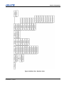
Roadster Series Menu
When using an Roadster Series projector with the YK200, these menus are available:
•
•
•
•
•
•
•
Welcome menu
DMX Number Changing menu
DMX Channel Visualization menu
Test Program menu
General Configuration menu
System Command menu
Information System menu
For an overview of the menu structure, refer to Figure 4-36 Menu Tree - Roadster Series, on page 4-21 .
4-16
YK200 User Manual
020-100629-02 Rev. 1 (08-2012)
Section 4: Operation
Welcome Screen
This menu displays the machine status when searching for home positions.
Question marks (?) indicate that the system is calibrating the pan and tilt
motors. When both pan and tilt home positions are found, the menu
indicates OK. The DMX address or the machine number is displayed.
NOTICE! If question marks persist after the YK200 is powered on and has reset, the pan or tilt axes may still
be locked.
Selecting a Menu
After the Welcome menu appears, press the or key to select the following main menu items. Once inside
a main menu item, however, the MENU key must be pressed first in order to select a different main menu with
the or keys.
DMX Address Modification Menu
1. From the Welcome menu, press once to select this menu item.
2. Press the OK key to change the DMX address.
3. Press the key to increase channel number.
4. Press the
key to decrease channel number.
5. Hold down the or
key to scroll quickly.
6. Press OK to validate this number.
7. Press MENU to return to the Welcome menu.
DMX Channel Visualization Menu
1. Press the or key to select this menu item.
2. Press the OK key to access the DMX screen.
3. Press the or
keys to review the DMX values for each channel
4. Press MENU to return to the Welcome menu.
Test Program Menu
1. Press the or key to select this menu item.
2. This menu has 6 submenus. Press the OK key to enter the first submenu:
Pan Test Submenu
1. Press the key to run the motor counterclockwise (as viewed from
above).
2. Press the
key to run the motor clockwise.
The LCD display indicates the coding point value of stripe converters in Hex mode (500 steps for 1 motor
cycle).
YK200 User Manual
020-100629-02 Rev. 1 (08-2012)
4-17
Section 4: Operation
3. Press the or key to select the next submenu.
Tilt Test Submenu
1. Press the key to run the motor clockwise (as viewed from yoke arm
side).
2. Press the
key to run the motor counterclockwise.
The LCD display indicates the coding point value of stripe converters in Hex mode (500 steps for 1 motor
cycle).
3. Press the or key to select the next submenu.
Shutter Test Submenu
1. Press the key to increment the value of the parameter.
2. Press the
key to decrease the value of the parameter.
Holding the or
key will quickly scroll through the range 0-255.
3. Press the or key to select the next submenu.
Focus Test Submenu
1. Press the key to increase the value.
2. Press the
key to decrease the value.
Holding the or
key will quickly scroll through the range 0-255.
3. Press the or key to select the next submenu.
Zoom Test Submenu
1. Press the key to increment the value of the parameter.
2. Press the
key to decrease the value of the parameter.
Holding the or
key will quickly scroll through the range 0-255.
3. Press the or key to select the next submenu.
Laser Test Submenu
1. Press the OK key to toggle the laser pointer ON or OFF.
2. Press MENU to return to the Welcome menu.
General Setup Menu
1. Press the or key to select this menu item.
2. This menu has 2 submenus. Press the OK key to enter the first submenu:
4-18
YK200 User Manual
020-100629-02 Rev. 1 (08-2012)
Section 4: Operation
Patch type Submenu
Allows you to address the YK200 with DMX channels or with UNIT
number.
1. Press the OK key to change from DMX to UNIT patch configuration.
2. Press the or key to select the next submenu.
Default Parameters Configuration Submenu
1. Press the OK key to restore the default parameters. The default parameter is DMX Channels address
setting.
2. Press MENU to return to the Welcome menu.
Command System Menu
1. Press the or key to select this menu item.
2. This menu has 9 submenus. Press the OK key to enter the first submenu, then or to navigate between
submenus if desired:
Video Control Submenu
1. Press the OK key to switch ON the video control.
Yoke Reset Submenu
1. Press the OK key to reset the pan and tilt motors (Home calibration).
2. The confirmation message Are You Sure? appears.
3. Press the OK key to confirm. The Welcome menu appears.
General Reset Submenu
1. Press the OK key to reset the pan and tilt motors, zoom, focus and video
control boards.
2. The confirmation message Are You Sure? appears.
3. Press the OK key to confirm. The Welcome menu appears.
Head Reset Submenu
1. Press the OK key to reset the zoom, focus and video control boards.
2. The confirmation message Are You Sure? appears.
3. Press the OK key to confirm. The Welcome menu appears.
YK200 User Manual
020-100629-02 Rev. 1 (08-2012)
4-19
Section 4: Operation
Zoom Reset Submenu
1. Press the OK key to reset the zoom control board.
2. The confirmation message Are You Sure? appears.
3. Press the OK key to confirm. The Welcome menu appears.
Focus Reset Submenu
1. Press the OK key to reset the focus control board.
2. The confirmation message Are You Sure? appears.
3. Press the OK key to confirm. The Welcome menu appears.
Zoom and Focus Reset Submenu
1. Press the OK key to reset the zoom and focus control boards.
2. The confirmation message Are You Sure? appears.
3. Press the OK key to confirm. The Welcome menu appears.
Command Video Reset Submenu
1. Press the OK key to reset the video control board.
2. The confirmation message Are You Sure? appears.
3. Press the OK key to confirm. The Welcome menu appears.
Pattern Submenu
1. Press the OK key to choose a pattern.
2. Press the or
key to scroll through 9 different patterns.
3. Press the OK key to confirm the choice. The Welcome menu appears.
Info System Menu
1. Press the or key to select this menu item.
2. Press the OK key to display the CPU software version.
4-20
YK200 User Manual
020-100629-02 Rev. 1 (08-2012)
Section 4: Operation
Figure 4-36 Menu Tree - Roadster Series
YK200 User Manual
020-100629-02 Rev. 1 (08-2012)
4-21
Section 4: Operation
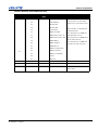
Roadster Series DMX Protocol
Table 4.2 lists the DMX channels and their function with a Roadster Series projector.
Table 4.2 Roadster Series DMX Parameters
Channel
DMX Value
Default DMX
Value
1
0-255
128
PAN HIGH
2
0-255
128
PAN LOW
3
0-255
128
TILT HIGH
4
0-255
128
TILT LOW
5
Comments
MOTOR MODE
MOTOR MODE THE SPEED AT
0-32
MODE 0
33-64
MODE 1
65-96
MODE 2
97-128
MODE 3
129-160
MODE 4
WHICH THE YOKE WILL MOVE.
DEFAULT MODE IS MODE 0,
WHICH IS THE SLOWEST. MODE 4
IS THE FASTEST. THE SLOWER
THE MODE, THE MORE ACCURATE THE YOKE WILL BE FOR
RECALL POSITIONS.
0
6
4-22
Function
0
YOKE FUNCTIONS
15
ZOOM-FOCUS RESET
20
YOKE RESET
25
HEAD RESET
30
ALL RESET
35
LASER ON
40
LASER OFF
86
LOAD
171
EXECUTE
FOR ALL THE FUNCTIONS, YOU
MUST CHOOSE THE FUNCTION
FIRST, THEN LOAD IT AND EXECUTE IT.
FOR EXAMPLE, TO RESET THE
YOKE:
SET CHANNEL #6 AT DMX 30
("ALL RESET" VALUE),
SET CHANNEL #6 AT DMX 86 TO
LOAD THE FUNCTION,
SET CHANNEL #6 AT DMX 171
TO EXECUTE THE FUNCTION.
YK200 User Manual
020-100629-02 Rev. 1 (08-2012)
Section 4: Operation
Table 4.2 Roadster Series DMX Parameters
Channel
DMX Value
Default DMX
Value
0
7
Function
VIDEO FUNCTIONS
20
VIDEO RESET
25
POWER ON
30
POWER OFF
35
LIVE VIDEO
36
MIRE CHECKER
37
MIRE GREY SCALE 16
38
MIRE GREY SCALE 256
39
MIRE WHITE
40
MIRE 50 GREY
41
MIRE BLACK
42
MIRE CONVERGENCE
43
MIRE 13 POINTS
44
MIRE COLOR BARS
86
LOAD
171
EXECUTE
8
0-255
128
ZOOM
9
0-255
128
FOCUS
10
0-255
255
SHUTTER
Comments
FOR ALL FUNCTIONS, YOU MUST
CHOOSE THE FUNCTION FIRST,
THEN LOAD IT AND EXECUTE IT.
FOR EXAMPLE, TO
THE PROJECTOR:
POWER ON
SET CHANNEL #7 AT DMX
("POWER ON" VALUE)
25
SET CHANNEL #7 AT DMX 86 TO
LOAD THE FUNCTION
SET CHANNEL #7 AT DMX 171
TO EXECUTE THE FUNCTION.
0 = CLOSED
255 = OPEN
YK200 User Manual
020-100629-02 Rev. 1 (08-2012)
4-23
5 Maintenance
Installers, service trained operators and all other users must maintain a safe operating environment at all times.
Read through this section in its entirety and understand all warnings and precautions before attempting to
operate the YK200 system.
5.1
Safety Warnings and Guidelines
5.1.1 General Precautions
All servicing must be performed by CHRISTIE accredited service technicians.
Use replacement parts that are manufacturer-approved only. Use of any other part other than
the ones specified by the manufacturer can result in fire, electric shock or risk of personal
injury and irreparable equipment damage.
For protection from electric shock, the YK200 must be grounded (earthed) to
protect against electrical shock and the AC power distribution circuit must be equipped with
a fuse or circuit breaker and ground-fault (earth-fault) protection.
Disconnect the YK200 from AC power before removing any cover or part –
including fuses – and when not in use. Covers shall only be removed by CHRISTIE accredited
service technicians.
Isolate the YK200 from power immediately if any power connector, power
cable, seal, cover or other component is damaged, defective, deformed, wet or showing
signs of overheating. Do not reconnect power until repairs have been completed.
Do not expose the YK200 to rain or moisture.
This symbol appears in this manual for procedures where a Pinching or Crushing
hazard between chain and sprocket exists. Keep hands clear when unit is
powered. Disconnect power before servicing.
This symbol appears in this manual for procedures where a Pinching or Crushing
hazard between rotating and stationary surfaces exists. Keep hands clear when
unit is powered. Disconnect power before servicing or apply rotation locks.
5.2
Pre-Operational Checklist
Before you operate the Christie Nitro YK200, check these items:
• Verify that the power cable connector is locked to the yoke base.
• Verify that the green LED is flashing on the control panel. This indicates that the yoke is receiving a DMX
signal.
• Verify that the connection between the projector and the yoke is correct.
YK200 User Manual
020-100629-02 Rev. 1 (08-2012)
5-1
Section 5: Maintenance
•
•
•
•
•
•
Verify that the yoke and projector can move freely without colliding with other objects.
Verify the pan and tilt functions on the yoke are unlocked. See 4.1.2 Locking System, on page 4-1.
Verify the Nitro Rigging Clamps are installed securely. See 4.3 Truss Mounting, on page 4-10.
Verify that the Quick Lock is locked and secured. See Quick Lock System, on page 3-6.
Verify that the yoke is properly grounded.
Verify that the AC power complies with the local building and electrical codes and has both overload and
ground-fault (earth-fault) protection.
• Verify that all power distribution equipment and cables are in good condition and rated for the requirements
of the connected devices.
• Verify that the DMX distribution has XLR 5 pin connectors. See Figure 4-17 DMX In and Thru XLR Connectors, on page 4-8.
5.3
Cleaning
5.3.1 Yoke
The plastic covers may be cleaned with water or alcohol 90.
5.3.2 Projector
Refer to the Maintenance section of the Roadster Series User Manual for cleaning information.
5.4
Lubrication
5.4.1 Chains
Chain lubricant may be applied as needed to the pan and tilt chains and checked at a minimum of every 3
months.
5.5
User-Serviceable Components
The components detailed below may be serviced by the user. All other service must be performed by a Christie
accredited service technician.
5.5.1 Yoke
Power Cable
Use only the AC power cable supplied. Do not attempt operation if the AC supply and
cable are not within the specified voltage and power range.
If the power cable is damaged or worn, replace it with the replacement part recommended by Christie.
5-2
YK200 User Manual
020-100629-02 Rev. 1 (08-2012)
Section 5: Maintenance
Microchip
If the CPU fails or a software upgrade is required, refer back to page 4-16 for microchip replacement details.
Fuses
Disconnect the YK200 from power before replacing a fuse. Replace fuses with
ones of the same type and rating. Never bypass or bridge a fuse. Covers shall only be
removed by CHRISTIE accredited service technicians.
The YK200 head box is protected by one fuse located in the fuse holder next to the power switch:
• T750mA for 200-240V
Two fuses are also located in Leg #2 of the Tripod. See Figure 5-1 and Table 5.1. The transformer primary
fuse is shown circled, and the secondary fuse (indicated by an arrow) is located in an inline fuse holder.
Table 5.1 Fuse Values
Description
POWER SUPPLY TRANSFORMER (150
VA)
Voltage
Range
Fuse protection
PRIMARY
208-230 V
T1.6A (250V) - USE ONLY CONQUER
ELECTRONICS CO., LTD # UTE1.60)
SECONDARY
22 V
T6.3A (250V)- USE ONLY SCHURTER
AG # 0034.3125
Figure 5-1 Power Supply Fuses
Chain
The chain tension should be checked every 3 months or less, depending on frequency of use.
YK200 User Manual
020-100629-02 Rev. 1 (08-2012)
5-3
Section 5: Maintenance
5.5.2 Projector
If a lens is changed, projector balance must be assessed.
NOTICE! With the YK200 power turned off and the tilt axis unlocked, balance is only achieved when the
projector does not tilt on its own when set to tilt angles of 0°, 45° and 90°. As a result, it may be necessary to
perform the balance adjustment more than once until this is achieved.
Refer to the Maintenance section of the Roadster Series User Manual for information on user-serviceable
projector components.
5-4
YK200 User Manual
020-100629-02 Rev. 1 (08-2012)
6 Troubleshooting
This section provides information and procedures for resolving common issues with the Christie Nitro YK200
yoke. If the problem can not be resolved, contact your dealer for assistance.
NOTE: Only Christie accredited technicians can perform service beyond the solutions listed in the
Troubleshooting Chart.
6.1
Yoke
Table 6.1 Troubleshooting Chart
Symptom
Action/Solution
Notes
Check MAIN ON/OFF switch is ON
No power (Red LED not lit on the control display planel)
Check that the Powercon connector
(black) is properly locked on the power/
DMX panel.
Check the power supply network
Check power supply fuses in LEG #2
No reset (after switching the yoke on /
Red LED is lit on the control display
panel)
Check that PAN and TILT Locks are properly released
If not, release them,
and switch the yoke
on again.
Check that PAN and TILT motor cables
are properly connected on motherboard
(CPU)
PAN & TILT detection is not working:
The reset sequence does not run properly : The control panel doesn’t display:
“PAN=ok TILT=ok DMX=###”
Check PAN & TILT sensors input connection on the CPU
Check detection LED indicators (orange
light) on the bottom of PAN & TILT sensors are on
Check PAN & TILT detection LED indicator on the CPU
The reset sequence does not run properly (slowly): PAN or TILT starts with a
high speed movement
Check motor cables and cables linking
motors to CPU
Check the PAN and TILT tension
PAN & TILT movement are not linear
(oscillate) when moving to a precise
position
YK200 User Manual
020-100629-02 Rev. 1 (08-2012)
For TILT : Check balance is properly
adjusted for the model of lens installed in
the projector
6-1
Section 6: Troubleshooting
Table 6.1 Troubleshooting Chart
Check DMX network linking Lighting console to the YK200. Ensure that DMX
cables used are certified DMX standard.
Check if DMX cable is properly plugged
into “DMX IN” input , on the power/DMX
panel
PAN & TILT cannot be controlled via
DMX Lighting console
Check DMX reception LED indicator on
the control display panel (green LED
should be flashing)
Check that DMX address is properly set
Check that “PAN=ok TILT=ok DMX=###”
is displayed on the control panel: DMX
signals will start to be received only after
the yoke reset is completed.
No power to the Roadster series
projector*
Check that power switch above power
cord on projector is in the ON position.
Check that power cable is properly
plugged and locked into the yoke sub
connection panel under the vertical cover.
Check that the MAIN ON/OFF switch on
the head box is ON
Check the powercon connector (blue) is
properly locked on the power/DMX head
box control display panel.
No power to the head box (Red LED on
the head box is not lit)
Check that power supply cable is also
properly connected to the yoke sub connection panel under the vertical cover.
Check power input fuse (external fuse
holder on head box).
Remove the head box cover and check
internal fuses.
Check DMX reception indicator on the
head box control display panel (green
LED flashing).
Roadster series projector doesn’t work
using DMX lighting console
Ensure that projector internal communication parameter is set to 19200 Baud.
Check DMX cable linking head box to the
YK200 yoke is properly plugged into the
head box and into the yoke sub connection panel under the vertical cover.
Check head box DMX address is set at
“1”.
Check that RS232 cable (SUB-D connector) is properly connected to RS232 OUTPUT on the Roadster series projector.
Video function (DMX channel #7) of the
Roadster series projector doesn’t work
properly.
6-2
Remove head box cover and ensure the
R232/DMX interface is properly set
(jumper).
YK200 User Manual
020-100629-02 Rev. 1 (08-2012)
Section 6: Troubleshooting
Table 6.1 Troubleshooting Chart
Roadster zoom & focus module doesn’t
work
Check that cable linking head box to
zoom/focus module is properly plugged
in (SUB-D).
Remove head box cover and check LED
indicators are lighting or flashing.
Zoom & focus module movement is not
linear.
No video signal transmitted*
Check that zoom/focus module is properly installed in the lens
Check that DVI or Ethernet cable link is
properly connected to the YK200 and to
the rear panel of the Roadster series projector.
Check that DVI signal input is activated
via the rear control panel of the Roadster
series projector
6.2
Projector
*Refer to the troubleshooting section of the Christie User Manuals for the Roadster Series projector.
YK200 User Manual
020-100629-02 Rev. 1 (08-2012)
6-3
7 Specifications
This section provides specifications for the Christie Nitro YK200 yoke. Due to continuing research, specifications are subject to change without notice.
7.1
General Capabilities
7.1.1 Pan and Tilt Movements
•
•
•
•
High Resolution - 8 arc minutes precision – Ratio 64:1
Linear command - Pan: 600°; Tilt: 270°
DC servo motor – 24 Volts
Maximum speeds: PAN: 8 sec TILT: 4.3 sec
7.1.2 Focus Control
• Remote - via DMX dedicated channels
7.1.3 Zoom Control
• Remote - via DMX dedicated channels
7.2
Physical
7.2.1 Yoke Dimensions
• H 1004 mm x W 830 mm x L
1183 mm
• H 39.5” x W 32.7” x L 46.6”
• Footprint - see Figure 7-1
7.2.2 Yoke Body
•
•
•
•
Body structure: Aluminum
Cover: thermoformed plastic
Color: grey-black
Pan and Tilt Lock for transport
and maintenance
Figure 7-1 YK200 Footprint
7.2.3 Mounting Options
• Floor mounted, upright
• Truss mounted with Nitro Rigging Clamp: upright or inverted
YK200 User Manual
020-100629-02 Rev. 1 (08-2012)
7-1
Section 7: Specifications
7.3
Weights
7.3.1 YK200
• 90 kg (198.4 lbs)
7.3.2 YK200 + Roadster Series Projector
• 200kg (440 lbs) without lens
7.4
Power Requirements
7.4.1 Voltage and Current
•
•
•
•
•
Europe: 230 VAC@50/60 Hz single phase
USA: 208 VAC@50/60 Hz dual phase
Operating current (Yoke only): 1A at 230VAC; 1.8A at 208VAC
Operating current (Yoke + Projector): 15A worst case
Power consumption: 150W max
7.4.2 Fuses
• Head Box: T750mA
• Power Supply Primary: T1.6A (Conquer Electronics Co., Ltd # UTE1.60)
• Power Supply Secondary: T6.3A (Schurter AG # 0034.3125)
7.5
Flight Case
7.5.1 Dimensions
• See Figure 7-2.
7.5.2 Weight
Empty
135 kg (297 lbs)
Figure 7-2 Flight Case Dimensions
With YK200 + Roadster Series Projector
335 kg (737 lb) without lens
7-2
YK200 User Manual
020-100629-02 Rev. 1 (08-2012)
Section 7: Specifications
7.6
Regulatory
• CE
• CSA
• UL Listed
7.7
Environment
• Maximum ambient temperature (Ta max): 45°C (113°F)
• Minimum ambient temperature (Ti max): -5°C (23°F)
7.8
Optional Components
• Nitro Rigging Clamp
YK200 User Manual
020-100629-02 Rev. 1 (08-2012)
7-3
Corporate offices
Worldwide offices
USA – Cypress
ph: 714-236-8610
United Kingdom
ph: +44 118 977 8000
Eastern Europe
ph: +36 (0) 1 47 48 100
Singapore
ph: +65 6877-8737
Japan
ph: 81-3-3599-7481
Canada – Kitchener
ph: 519-744-8005
France
ph: +33 (0) 1 41 21 00 36
Middle East
ph: +971 (0) 4 299 7575
Beijing
ph: +86 10 6561 0240
South Korea
ph: +82 2 702 1601
Germany
ph: +49 2161 664540
Spain
ph: + 34 91 633 9990
Shanghai
ph: +86 21 6278 7708
For the most current technical documentation, please visit www.christiedigital.com