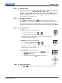
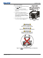
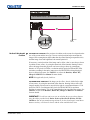
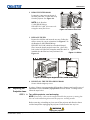
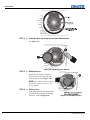
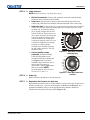
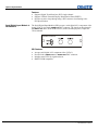
1
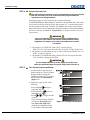
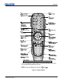
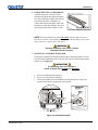
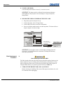
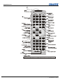
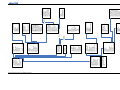
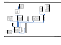
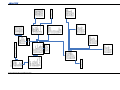
Roadster, Matrix WU, Mirage S+/HD/WU SETUP GUIDE 020-100342-02 Roadster, Matrix WU, Mirage S+/HD/WU SETUP GUIDE 020-100342-02 NOTICES COPYRIGHT AND TRADEMARKS © 2005-2011 Christie Digital Systems USA, Inc. All rights reserved. All brand names and product names are trademarks, registered trademarks or trade names of their respective holders. REGULATORY The product has been tested and found to comply with the limits for a Class A digital device, pursuant to Part 15 of the FCC Rules. These limits are designed to provide reasonable protection against harmful interference when the product is operated in a commercial environment. The product generates, uses, and can radiate radio frequency energy and, if not installed and used in accordance with the instruction manual, may cause harmful interference to radio communications. Operation of the product in a residential area is likely to cause harmful interference in which case the user will be required to correct the interference at the user’s own expense. This Class A digital apparatus complies with Canadian ICES-003. Cet appareil numérique de la classe A est conforme à la norme NMB-003 du Canada. 㧊 ₆₆⓪ 㠛ⶊ㣿 (A ) 㦒⪲ 㩚㧦䕢㩗䞿❇⪳㦚 䞲 ₆₆㧊㡺┞ 䕦ⰺ㧦 ⡦⓪ ㌂㣿㧦⓪ 㧊㩦㦚 㭒㦮䞮㔲₆ ⧒Ⳇ , Ṗ㩫 㣎㦮 㰖㡃㠦㍲ ㌂㣿䞮⓪ ộ㦚 ⳿㩗㦒⪲ 䞿┞┺ . GENERAL Every effort has been made to ensure accuracy, however in some cases changes in the products or availability could occur which may not be reflected in this document. Christie reserves the right to make changes to specifications at any time without notice. Performance specifications are typical, but may vary depending on conditions beyond Christie's control such as maintenance of the product in proper working conditions. Performance specifications are based on information available at the time of printing. Christie makes no warranty of any kind with regard to this material, including, but not limited to, implied warranties of fitness for a particular purpose. Christie will not be liable for errors contained herein or for incidental or consequential damages in connection with the performance or use of this material. The product is designed and manufactured with high-quality materials and components that can be recycled and reused. This symbol means that electrical and electronic equipment, at their end-of-life, should be disposed of separately from regular waste. Please dispose of the product appropriately and according to local regulations. In the European Union, there are separate collection systems for used electrical and electronic products. Please help us to conserve the environment we live in! Canadian manufacturing facility is ISO 9001 and 14001 registered. GENERAL WARRANTY STATEMENTS For complete information about Christie’s limited warranty, please contact your Christie dealer. In addition to the other limitations that may be specified in Christie’s limited warranty, the warranty does not cover: a. Damage occurring during shipment, in either direction. b. Projector lamps (See Christie’s separate lamp program policy). c. Damage caused by use of a projector lamp beyond the recommended lamp life, or use of a lamp supplied by a supplier other than Christie. d. Problems caused by combination of the product with non-Christie equipment, such as distribution systems, cameras, video tape recorders, etc., or use of the product with any non-Christie interface device. e. Damage caused by misuse, improper power source, accident, fire, flood, lightening, earthquake or other natural disaster. f. Damage caused by improper installation/alignment, or by product modification, if by other than a Christie authorized repair service provider. g. For LCD projectors, the warranty period specified applies only where the LCD projector is in “normal use.” “Normal use” means the LCD projector is not used more than 8 hours a day, 5 days a week. For any LCD projector where “normal use” is exceeded, warranty coverage under this warranty terminates after 6000 hours of operation. h. Failure due to normal wear and tear. PREVENTATIVE MAINTENANCE Preventative maintenance is an important part of the continued and proper operation of your product. Please see the Maintenance section for specific maintenance items as they relate to your product. Failure to perform maintenance as required, and in accordance with the maintenance schedule specified by Christie, will void the warranty. Table of Contents 1 Introduction 1.1 1.2 1.3 The Projectors ................................................................................................... 1-1 Components ...................................................................................................... 1-2 Purchase Record and Warranty Registration .................................................... 1-3 2 Installation & Setup 2.1 2.2 2.3 2.4 Quick Setup ...................................................................................................... 2-1 Installation Considerations................................................................................ 2-4 Projector Position and Mounting ...................................................................... 2-6 Power Connection ............................................................................................. 2-8 Basic Operation 3.1 3.2 3.3 3.4 3.5 3.6 Overview........................................................................................................... 3-1 Projector Basics ................................................................................................ 3-1 Using the Keypads ............................................................................................ 3-3 Navigating the Menus ..................................................................................... 3-13 Using Inputs and Channels ............................................................................. 3-17 Adjusting the Image ........................................................................................ 3-22 4 Maintenance 4.1 4.2 4.3 4.4 Warnings and Guidelines .................................................................................. 4-1 Replacing Keypad Batteries.............................................................................. 4-4 Lamp and Filter Replacement ........................................................................... 4-4 Replacing the Projection Lens .......................................................................... 4-9 5 Troubleshooting 6 5.1 5.2 5.3 5.4 Displays ............................................................................................................ 5-1 Lamp ................................................................................................................. 5-3 Ethernet ............................................................................................................. 5-4 3D Sync Input ................................................................................................... 5-4 Specifications 6.1 Specifications .................................................................................................... 6-1 A B C D E Keypad Reference ............................................................................................ A-1 Serial Communication Cables.......................................................................... B-1 System Integration ........................................................................................... C-1 Optional Input Modules ................................................................................... D-1 Menu Tree........................................................................................................ E-1 3 Appendices NOTE: Due to continuing research, all information in this manual is subject to change without notice. Roadster, Matrix WU, Mirage S+/HD/WU Setup Guide 020-100342-02 Rev. 1 (04-2011) i Section 1 Introduction 1.1 The Projectors Every effort has been made to ensure the information in this document is accurate and reliable; however, due to constant research the information in this document is subject to change without notice. This guide applies to the following projector models: Roadster S+12K Roadster S+16K Roadster S+20K Roadster HD12K Roadster HD18K Mirage S+12K Mirage S+14K Mirage S+16K Mirage S+20K Mirage HD12 Mirage HD18 Mirage WU12 Mirage WU18 Matrix WU12 Main Features General DLP™ three-chip electronics with true 1400 x 1050 (SXGA+) or 1920 x 1200 (WUXGA) resolution, and 1920 x 1080 (HD) native resolution Ten-bit digital video processing Single-lens design with field-interchangeable, fast-change lens – no tools needed Modular design for easy servicing Intelligent Lens System (ILS) to save and restore lens settings Built-in handles and multiple rigging points lenses motorized Inputs There are two different types of Input face plate configurations (model dependant). Refer to Figure 1.1 & 1.2. These configurations may include the following inputs: One analog RGBHV/YPbPr input with five BNCs One DVI-I input for either digital RGB/YCrCb or analog RGB/YPbPr signals One analog composite-video input One analog S-video input Built-in multi-standard video decoder (NTSC, NTSC 4.43, PAL, PAL-M, PAL-N, PAL-60 AND SECAM) One Dual SD/HD-SDI module (standard on Roadster models only) Compatible with all currently used HDTV formats Roadster, Matrix WU, Mirage S+/HD/WU Setup Guide 020-100342-02 Rev. 1 (04-2011) 1-1 Introduction For simplicity, this manual refers to the configuration in Figure 1.1 only. Figure 1.1 Figure 1.2 1.2 Components Ensure the following standard components have been received: 1-2 Projector Infrared (IR) remote keypad and conversion cable Power cord (NOTE: non-detachable on Roadster S+ 20K/HD18K/Mirage HD18/Mirage S+20K) Using 3D in Mirage Manual (NOTE: for Mirage Series only) 3D Stereo Sync Cable (NOTE: for Mirage Series only) Roadster, Matrix WU, Mirage S+/HD/WU Setup Guide 020-100342-02 Rev. 1 (04-2011) Introduction Differences Between Models Model Name Lamp Type Dual SD/HDSDI Module Roadster S+12K Roadster HD12K Roadster S+16K Roadster HD18K Roadster S+20K Matrix WU12 Mirage HD12 Mirage WU12 Mirage S+12K Mirage S+14K Mirage S+16K Mirage HD18 Mirage WU18 Mirage S+20K 2.0 kW 2.0 kW 2.4 kW 3.0 kW 3.0 kW 2.0 kW 2.0 kW 2.0 kW 2.0 kW 2.4 kW 2.4 kW 3.0 kW 3.0 kW 3.0 kW Optional Optional Optional Optional Optional Optional Optional Optional Optional 1.3 Purchase Record and Warranty Registration 3D Not Available Not Available Not Available Not Available Not Available Not Available Adjustable Iris Stacking Mounts 4 Top Eyebolts Integral Rigging Hardware Optional Optional Optional Optional Optional Optional Optional Optional Optional Optional Optional Optional Optional Optional Optional Optional Optional Optional Whether the projector is under warranty or the warranty has expired, Christie’s highly trained and extensive factory and dealer service network is always available to quickly diagnose and correct projector malfunctions. Service manuals and updates are available to service technicians for all projectors. If you encounter any problems with the projector and require assistance, contact your dealer or Christie Digital Systems. Fill out the information in the table below and keep with your records for future reference. Purchase Record Dealer: Dealer Phone Number: Projector Serial Number: Purchase Date: Installation Date, if applicable: NOTE: The serial number can be found on the license label, which is located at the back of the projector. You can also register your product on-line by visiting www.christiedigital.com Service and Support Product Registration. This will keep you in touch with all the latest product information, such as updates, technical bulletins, downloads and Christie newsletters. For complete details on the warranty of your Christie product, please contact your Christie dealer. Roadster, Matrix WU, Mirage S+/HD/WU Setup Guide 020-100342-02 Rev. 1 (04-2011) 1-3 Section 2 Installation & Setup 2.1 Quick Setup STEP 1 The instructions provided here are for those that are familiar with the projector and wish to quickly set it up and use it temporarily. Refer to the remaining subsections of this manual for a more complete setup. Install a Projection Lens The projection lens is shipped separately from the projector and must be installed prior to setting up the projector. Install the projection lens as described in 4.5 Replacing the Projection Lens. Remove the lens plug from the lens opening in the projector before installing the lens. Remove the lens when shipping the projector and reuse the lens plug to prevent dust and debris from entering and settling on the projector’s optical components. STEP 2 Position the Projector Place the projector on a sturdy, level surface and position it so that it is perpendicular to the screen at a suitable distance. In general, the further back the projector is positioned from the screen, the larger the image will be. If required, you can level the projector by adjusting its three feet. With the projector positioned perpendicular to the screen the image will appear rectangular instead of keystoned. For more detailed instructions on positioning the projector refer to Projector Position and Mounting later in this section. STEP 3 Connect a Source Located at the back of the projector is the input panel where all source connections are made. Each input is clearly labeled for easy identification. Using the appropriate cable(s), connect your source. Connect RGB and YPbPr sources to INPUT 1 located in the upper right corner of the input panel. Use the DVI-I connector at INPUT 2 to connect analog or digital display signals. Connect composite video to INPUT 3 and S-video to INPUT 4. NOTE: One of the available optional input modules can be installed at INPUT 5 or for additional connections. INPUT 6 Refer to 2.4 Connecting Sources for more details on connecting a specific source. Roadster, Matrix WU, Mirage S+/HD/WU Setup Guide 020-100342-02 Rev. 1 (04-2011) 2-1 Installation & Setup STEP 4 Connect the Line Cord The North American-rated line cord is provided with each projector. Ensure that you are using a line cord, socket and power plug that meets the appropriate local rating standards. Connect the projector’s line cord to the AC receptacle (Roadster S+20K/HD18K/Mirage HD18/Mirage S+20K have non-detachable line cords) at the lower corner on the rear of the projector, and to proper AC—note the outlet must be near the equipment and easily accessible. Use only the line cord provided with the projector or a power cord of appropriate ratings that comply with regional standards. (See below and refer to Section 6 – Specifications for complete details on all power requirements). WARNING Line cord replacement must be performed by qualified service personnel in accordance with specific national electrical safety regulations. For details, refer to the Service Manual and contact your dealer. The Roadster S+12K/HD12K, Matrix WU12, and the Mirage HD12/WU12/S+12K require 200-240 VAC, 50-60 Hz, 12 amps @ 200 VAC. The Roadster S+16K and the Mirage S+14K/S+16K require 200-240 VAC, 5060 Hz, 16 amps @ 200 VAC. The Roadster S+20K/HD18K/Mirage HD18/WU18/S+20K require 200-240 VAC, 50-60 Hz, 20 amps @ 200 VAC. WARNING Do not attempt operation if the AC supply and cord are not within the specified voltage and power range. Refer to Section 6. STEP 5 Turn On the Projector and Lamp 1. On the projector, turn the power breaker/switch on. The LCD Status Display Window displays the initializing window for 15 seconds, and then indicates POWER OFF (Figure 2.1). 2. Using the keypad, do one of the following: • Press and hold briefly to toggle the lamp on. • Press and release followed . immediately by • Press to toggle from the off state. The LCD Status Display Window will display Powering Up and then, Power On (Figure 2.1) while the two-digit Status/Error Code Window will display ON. 2-2 Figure 2.1. Turning on the projector Roadster, Matrix WU, Mirage S+/HD/WU Setup Guide 020-100342-02 Rev. 1 (04-2011) Installation & Setup STEP 6 Select a Source Using either keypad, press Input 1 , Input 2 , Input 3 , Input 4 , Input 5 , or Input 6 to select and display the image for the source you connected in Step 3. The display will resize as needed and produce largest possible image for the type of source present. NOTE: Refer to Menu Tree, Appendix E, this allows you to quickly navigate to a specific menu, and associated options/secondary menus. STEP 7 Optimize the Display Auto on the remote keypad) to initiate an Press Setup on the built-in keypad (or automated process in which the projector optimizes critical display parameters such as size, position, pixel tracking, etc., for the current source. Auto Setup can save time in perfecting a display and you can modify the adjustments later as desired. Refer to Section 3. STEP 8 Lens Adjustments ZOOM: With the input image displayed: If remote keypad: Press Zoom If built-in keypad: Press Zoom or or . . Hold the key down to see the effect – arrows in the display indicate the direction of the zoom (Figure 2.2). Figure 2.2 FOCUS: With the input image displayed: If remote keypad: Press Focus If built-in keypad: Press Focus or or . . Hold the key down to see the effect – arrows in the display indicate the direction of the focus (Figure 2.3). LENS OFFSET: To move the image: If remote keypad: Press either Lens H (Figure 2.4). If built-in keypad: Press Lens Shift Figure 2.3 or Lens V and use the arrow keys. Figure 2.4 Step 9 Image Adjustments Press Menu or (remote) to access display parameters described in Section 3. Roadster, Matrix WU, Mirage S+/HD/WU Setup Guide 020-100342-02 Rev. 1 (04-2011) 2-3 Installation & Setup 2.2 Installation Considerations Although this projector delivers a high-brightness, high-quality output, the final display quality could be compromised if the projector is not properly installed. This subsection discusses issues you should consider before proceeding with a final installation. Even if you do not intend to use the projectors in a fixed and permanent installation, the following information will help you to better understand what you can do to enhance display performance. Lifting, Hoisting, For any new installation, you will likely have to safely lift or hoist the projector into and Stacking place. Keep in mind the following guidelines for safety. Lifting All models include handles for convenient hand transport only, such as when a projector is lifted from a shipping container to a table. Note the following: The handles are intended to support the weight of one projector only. The handles are intended to support a projector for a brief time only. The handles are not safety points, nor points from which to hoist or suspend the projector. WARNINGS The handles cannot support more than ONE projector. Do not use handles for extended time periods. Do not use the handles as safety points, or as points from which to suspend or hoist the projector. Hoisting Four integral rigging points on the top of the projector (Figure 2.5) and eight on the bottom (Figure 2.6) enable either upright or inverted hoisting. For either orientation, hoist an individual projector, or up to three projectors in a stack. Figure 2.5. Top Rigging Points 2-4 Roadster, Matrix WU, Mirage S+/HD/WU Setup Guide 020-100342-02 Rev. 1 (04-2011) Installation & Setup RULES FOR ALL HOISTING: Use at least four rigging points for hoisting up to three projectors. Connect safety cables, and rigging equipment to the designated locations on the projector. Use hoisting and rigging equipment suitable to your application such as clamps, cables, eyebolts, or straps, and which accommodate the load rating. All integral, metric hardware on the projector accepts an M12 thread only. Never hoist a projector by its feet, handles, or any other component (Figure 2.7). Figure 2.6. Bottom Rigging Points WARNING Use metric hardware only. Never force incompatible threads. IMPORTANT Remove the lens before hoisting a projector. WARNING Never hoist a projector by its feet, handles, or any other component. Figure 2.7. NEVER Use Handles for Hoisting or as Safety Points Roadster, Matrix WU, Mirage S+/HD/WU Setup Guide 020-100342-02 Rev. 1 (04-2011) 2-5 Installation & Setup Installation Type Choose the installation type that suits your needs: front or rear screen, floor mount or inverted mount. ADVANTAGES Easy to set up Can be moved or changed quickly Easy to access CONSIDERATIONS Shares floor space with audience CONSIDERATIONS Installation is more permanent It is more difficult to access the projector CONSIDERATIONS Requires separate room Installation cost is usually higher CONSIDERATIONS Requires separate room Installation cost is usually higher CONSIDERATIONS Requires separate room Installation cost is usually higher Front Screen, Inverted Mount (ceiling) Installation ADVANTAGES Does not take up audience space Projector is unobtrusive Projector cannot be accidentally moved Rear Screen, Floor Mount Installation ADVANTAGES Projector is completely hidden Projector is easily accessed Usually good ambient light rejection Rear Screen, Inverted Mount (ceiling) Installation ADVANTAGES Projector is completely hidden Usually good ambient light rejection Rear Screen, Floor Mount with Mirror 2.3 Projector Position and Mounting ADVANTAGES Projector is completely hidden Usually good ambient light rejection Requires less space behind screen than other rear screen installations Throw distance Throw distance is the distance measured from your projector’s front feet to the screen. This is an important calculation in any projector installation as it determines whether or not you have enough room to install your projector with a desired screen size and if your image will be of the right size for your screen. You can quickly estimate the throw distance by taking the horizontal width of the screen and multiplying it by the lens throw ratio. The result of this calculation tells you roughly how far back the projector should be positioned from the screen in order to project a focused image large enough to fill the screen. For example: Screen Width = 10 feet Lens Type is 0.7:1 Throw Distance (TD) = 10 feet x 0.7 = 7 feet IMPORTANT! Once you determine the type of lens and screen size you’re going to use, calculate the precise throw distance. Due to lens manufacturing tolerances for lens focal length, actual throw distance can vary 5% between lenses described as having the same throw ratio. 2-6 Roadster, Matrix WU, Mirage S+/HD/WU Setup Guide 020-100342-02 Rev. 1 (04-2011) Installation & Setup Throw Distance (TD) = (Screen Width X Lens Type) SCREEN Vertical & Horizontal THE VERTICAL POSITION of the projector in relation to the screen also depends on the Position size of the screen and the lens type. Correct vertical position helps ensure that the image will be rectangular in shape rather than keystoned (having non-parallel sides) and that image focus and brightness both remain optimized. If necessary, vertical position of the image can be offset—that is, moved up or down in relation to lens center—by using the motorized offset function. Starting with no offset, the image from this projector can be moved up or down by a maximum distance of 525 pixels for SXGA+ resolution and 643 pixels for HD and WUXGA resolution, resulting in the entire image (more for HD/WUXGA) being displayed above or below lens center. See Table 2.1 or refer to the Roadster, Matrix WU, Mirage S+/HD/WU User Manual for more details. NOTE: Not applicable for the fixed lens. THE HORIZONTAL POSITION of the image can be offset—that is, shifted left or right of lens center—by using the motorized offset function. Starting with no offset, the image from this projector can be moved left or right by a maximum distance of 350 pixels for SXGA+ resolution and 403 pixels for HD and WUXGA resolution, resulting in approximately 75% of the image displayed to one side of lens center. See Table 2.1 or refer to the Roadster, Matrix WU, Mirage S+/HD/WU User Manual for more details. IMPORTANT! Use the lens and screen size to calculate the precise throw distance using the tables provided in the Dealer Section of the Christie Website, PN 020100298-xx. Due to lens manufacturing tolerances for lens focal length, actual throw distance and vary ±5% between lenses with the same nominal throw ratio. Roadster, Matrix WU, Mirage S+/HD/WU Setup Guide 020-100342-02 Rev. 1 (04-2011) 2-7 Installation & Setup Table 2.1. Lens Offsets Lens Type (All motorized lenses) Offset Movement or or Max. Amount of Display Max. Amount of Display Above or Below Lens Center Right or Left of Lens Center 100% 50% 1050 pixels or 100% 1050 pixels or HD Lenses 119% 42% 1183 pixels or 100% 1363 pixels or 71% WU Lenses 112% 54% 1243 pixels or 100% 1478 pixels or 77% SXGA+ Lenses 75% NOTES: 1) Offsets are subject to 7% centering tolerance 2) % Offset = # pixels of offset / half panel resolution x 100. 3) 0.73:Fixed and 1.16-1.49 Zoom Lenses have less offset. Refer to Specification section, Lenses for more details. Mounting There are several methods for mounting the projector. Depending on your chosen installation, one method may be more suitable than another. In typical front and rear screen installations the projector can be mounted to a secure and level surface, such as a table or cart. Carts are useful when the projector has to be moved during a presentation or from site to site. It is recommended you lock the wheels on a cart, when it’s in position, to prevent someone from accidentally moving it during a presentation. - The projector can also be inverted and suspended from the ceiling using a specially designed ceiling mount fixture. This type of mounting is recommended for fixed installations and for those that want the projector out of plain view or have a limited amount of space for projector and audience. For more information, contact your dealer. CEILING MOUNT Use only the CHRISTIE approved ceiling mount kit designed for your projector. Refer to the installation instructions and safety guidelines provided in the kit. Folded Optics In rear screen applications (Figure 2.8) where space behind the projector is limited, a mirror may be used to fold the optical path. The position of the projector and mirror must be accurately set. Consult your dealer or Christie for details. Figure 2.8. Rear Screen 2.4 2-8 Power Connection The North American rated line cord is provided with each projector. Ensure that you are using a line cord that meets the appropriate rating standards. Plug the projector’s high-current line cord into the line input socket located in the lower right corner of the rear panel of the projector, then plug the 3-pronged end of the line cord into a grounded AC outlet. Ensure the socket outlet is installed near the equipment and is easily accessible. Input voltage to all Roadster and Mirage models must be capable of 200 –240 VAC. Use the proper power source and the highcurrent rated line cord provided. Refer to Section 6, Specifications for all power requirements. Roadster, Matrix WU, Mirage S+/HD/WU Setup Guide 020-100342-02 Rev. 1 (04-2011) Installation & Setup WARNING Do not attempt operation if the AC supply and cord are not within the specified voltage and power range. Caution for Shutdowns: Once the projector is turned off ( ), the lamp cooling fans will continue to run for approximately five minutes to ensure that the projector and lamp have sufficiently cooled, at which point the fans will automatically shut off. To avoid thermal stress that can lead to premature lamp failure, never unplug the line cord while the lamp cooling fans are running, and never unplug to power down. Roadster, Matrix WU, Mirage S+/HD/WU Setup Guide 020-100342-02 Rev. 1 (04-2011) 2-9 Section 3 Operation 3.1 Overview This section explains how to use the projector once it has been installed. Please read through these pages before using the projector for the first time. An understanding of projector features and how to access them will help you to take full advantage of the capabilities of the projector within minutes. NOTE: Installation involves locating the projector and adjusting it for use at that location. If you have not yet installed the projector, refer to Section 2, Installation and Setup. 3.2 Projector Basics This section explains how to effectively operate the projector once it has been installed. It is recommended that you read this section and familiarize yourself with the components and the available menu options before you begin using your projector for the first time. Projector components and functions are illustrated below (Figure 3.1). Figure 3.1. Basic Projector Components (* on Roadster series only) Lens Release Push lens release to enable the lens to be rotated for removal. Handle Handles are for brief hand transport only. Not used for hoisting, rigging, or as safety points. Roadster, Matrix WU, Mirage S+/HD/WU Setup Guide 020-100342-02 Rev. 1 (04-2011) 3-1 Operation Stacking Mounts & Stacking Legs NOTE: Optional on Mirage models. Used for stacking up to three projectors. Refer to Section 2 for details. WARNING Use Christie stacking mounts only. Adjustable Feet Turn the four adjustable feet to increase or decrease height and/or tilt as needed. For most installations the projector will likely be slightly inclined to match the screen tilt – this reduces the amount of vertical offset required. Refer to 2.3, Projector Position and Mounting or the Roadster, Matrix WU, Mirage S+/HD/WU User Manual for more details. Filter Panel The filter door is a louvered grille for air intake. Remove to access and replace air filter. Lamp Door The lamp door is a louvered grille for accessing and replacing the lamp module. NOTE: Lamp replacement requires a qualified service technician. Input Panel The input panel wires the projector to inputs (sources) and controllers such as PCs. AC Power Input & Monitoring COMPOSITE/S-VIDEO INPUT - Accepts a composite video, DVI and S-Video signal from devices such as VCRs. RGB INPUT - Accepts RGB and sync signals from devices such as computers, as well as composite video, S-Video or YPbPr component signals. RS-232 SERIAL INTERFACE (WITH LOOP THROUGH) - Allows one or more projectors to be remotely controlled by a computer or controller, RS-422 INTERFACE - Allows one or more projectors to be remotely controlled by an RS-422 compatible computer or controller (such as the Two-Way Controller accessory). AC LINE CORD INPUT - Use the AC supply specified, and always use the line cord recommended by Christie. See Section 6. Before unplugging, wait until the main blower turns off or the LCD status reads Power Off. Model Roadster S+12K/HD12K Matrix WU12 Mirage HD12 Mirage WU12 Mirage S+12K Roadster S+16K Mirage S+14K Mirage S+16K Mirage HD18 Mirage WU18 Roadster S+20K/HD18K Mirage S+20K AC Power Specifications 200-240 VAC, 50-60 Hz, max. 12 amps @ 200VAC 200-240 VAC, 50-60 Hz, max. 12 amps @ 200VAC 200-240 VAC, 50-60 Hz, max. 12 amps @ 200VAC 200-240 VAC, 50-60 Hz, max. 12 amps @ 200VAC 200-240 VAC, 50-60 Hz, max. 12 amps @ 200VAC 200-240 VAC, 50-60 Hz, max. 16 amps @ 200VAC 200-240 VAC, 50-60 Hz, max. 16 amps @ 200VAC 200-240 VAC, 50-60 Hz, max. 16 amps @ 200VAC 200-240 VAC, 50-60 Hz, max. 20 amps @ 200VAC 200-240 VAC, 50-60 Hz, max. 20 amps @ 200VAC 200-240 VAC, 50-60 Hz, max. 20 amps @ 200VAC 200-240 VAC, 50-60 Hz, max. 20 amps @ 200VAC WARNING Do not attempt operation if the AC supply is not within the specified voltage and power range. Use the specified line cord. 3-2 Roadster, Matrix WU, Mirage S+/HD/WU Setup