1
2.4
Measurements
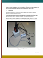
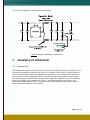
The measurement is started by connecting the voltage clips of the generator to the wires
connecting capacitor units in parallel.
Make sure that the capacitors to be measured are fully discharged before connecting the
voltage clips as discharging the capacitor to the generator output may damage the
generator. Please refer to the Instruction Manual of the capacitor bank
Also avoid short-circuiting the clips as the internal protection fuse may blow. Make sure that
both jaws of the clip make a good contact to the wires.
The generator should be connected to the center of the parallel-connected capacitor units so
that the current supplied by the generator will be equally divided between all units in the
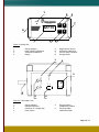
bank to maximize accuracy. Now the generator and display units can be switched on (Fig. 3:
button 2 and Fig. 4: switch 4). Check that the both overload leds at the side of the
Generator Unit (Fig. 4: 2) are off, otherwise the generator may be overloaded or in shortcircuit.
The generator and display units should be kept powered for appr. 15 minutes before starting
the actual measurements to let the measurement voltage and display to stabilize. After the
warmup the calibration procedure presented in section 2.3 should be carried out. When the
meter is calibrated, the actual measurements can take place.
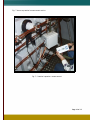
The capacitor unit is measured by selecting a proper measuring range (Fig. 3: 5) and placing
the current clamp on the bushing of the capacitor unit and the value can be read out after
some seconds as the reading is stabilized. The current clamp should be positioned as far as
possible from wires to the lower part of the insulator as the current in wires can weaken the
measuring accuracy.
Page 9 of 13