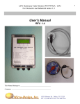
1
LPG Stationary Tank Monitor PN#94442A
For Domestic and Industrial tanks
User’s Manual
REV. 1.2
This Manual belongs to: _______________________________________
Company: __________________________________________________
10210 Monroe Dr. Dallas, TX 75229
Tel: 972-488-8725 Fax: 972-488-8724
1
LPG Stationary Tank Monitor PN#94442A
For Domestic and Industrial tanks
2
Proprietary Notice
This document and its contents are proprietary to Micro-Design, Inc and shall not be reproduced, copied
or used in whole or in part without the written consent of an officer of Micro-Design, Inc.
This document is for information purposes only and is subject to change without notice.
Micro-Design, Inc thanks you for purchasing this product and hopes that it can fulfill all your needs now
and in the future.
10210 Monroe Dr. Dallas, TX 75229
Tel: 972-488-8725 Fax: 972-488-8724
LPG Stationary Tank Monitor PN#94442A
For Domestic and Industrial tanks
Revision History
Version
-------------1.0
1.1
1.2
Page Date
--------
Reason
----------------------------------------------------------------------------
10/18/2004
01/14/2006
02/28/06
Initial Release
Added multiple sender setting details and updated Serial menu
Added -48 VDC connection details
Please Note:
Micro-Design, Inc encourages and appreciates customer
feedback regarding errors or improvements for this document.
If you have any questions regarding this manual or this
product, please call or write to the following:
Please respond to:
Micro-Design, Inc
10210 Monroe Dr.
Dallas, TX 75229
Tel: 972-488-8725
Fax: 972-488-8724
Internet Home page: www.micro-design.com
10210 Monroe Dr. Dallas, TX 75229
Tel: 972-488-8725 Fax: 972-488-8724
3
LPG Stationary Tank Monitor PN#94442A
For Domestic and Industrial tanks
4
Table of Contents
Features.................................................................................................................................................................. 5
Product Overview................................................................................................................................................. 6
1) LCD Display .............................................................................................................................................. 6
2) Alarm Relay............................................................................................................................................... 7
3) Analog Outputs ......................................................................................................................................... 8
4) Connection Details .................................................................................................................................... 9
a) Jumper settings for using MDi Sensors PN# 944417 or PN# 944418:................................................. 10
b) Connection Detail for Rochester Remote Sender ................................................................................. 11
5) -48 VDC Power Source Connection Details.......................................................................................... 14
PC Connections using RS232 Serial Interface ................................................................................................. 15
a) RS232 serial port 1 connection and operation (DEV port) ................................................................... 15
b) RS232 serial port 2 connection and operation (COM port).................................................................. 17
Programming Low and High Set Points ........................................................................................................... 19
Hardware Installation ........................................................................................................................................ 20
Monitor mounting dimensions ........................................................................................................................... 21
Monitor Specifications ........................................................................................................................................ 22
Sender Specifications .......................................................................................................................................... 23
Most frequently asked questions and answers (Q & A) .................................................................................. 24
10210 Monroe Dr. Dallas, TX 75229
Tel: 972-488-8725 Fax: 972-488-8724
LPG Stationary Tank Monitor PN#94442A
For Domestic and Industrial tanks
5
Features
The 94442A Stationary Tank Monitor (STM) is used for measuring LPG level in a tank. It can be
installed indoors or outdoors at a convenient location that can be up to 1000 feet from the tank. A level sender is
also included which must be installed in the float gage located on the tank. The LPG tank does not have to be
emptied or purged to install the sender. It’s universal design fits most junior and senior LPG float gages and
includes a direct read pointer that can be used to indicated LPG level at the tank
•
Monitors 2 LPG Tank Levels (Sensor for second tank optional)
•
State-of-the-art intelligent microprocessor based electronics
•
Large LCD readout indicating Level, Low Set Point and High Set Point for each channel
•
Hi/Lo alarm set points programmable using built- in pushbuttons
•
One Form “C” (NC-N-NP) contact available for each channel. Contact rating 120VAC @ 3 Amps
•
Analog Output for each channel, 0 to 5 VDC standard, 4-20 mA optional
•
RS232 Serial Interface for direct connectio n to PC/RTU or PLC
•
NEMA 4 enclosure suitable for outdoor use
•
Operated on 12 to 24 VDC power. Includes 120 VAC wall transformer for AC operation.
•
One LPG sensor included to fit standard 2” junior float gage
10210 Monroe Dr. Dallas, TX 75229
Tel: 972-488-8725 Fax: 972-488-8724
6
LPG Stationary Tank Monitor PN#94442A
For Domestic and Industrial tanks
Product Overview
The monitor contains the following:
1) LCD Display
Figure 1 indicates LPG level and corresponding Low and High Set points for 2 individual tanks.
Top Line indicates parameters for Tank 1 and second line for Tank 2.
Level
Tank 1
Tank 2
LCD Display
Low Set Point
Blue PB#1
L1 62% Lo30 Hi80
L2 XX% Lo30 Hi80
“XX” = No Sensor
Figure 1
High Set Point
Blue PB#2
Low Set Point
Blue PB#3
High Set Point
Blue PB#4
10210 Monroe Dr. Dallas, TX 75229
Tel: 972-488-8725 Fax: 972-488-8724
LPG Stationary Tank Monitor PN#94442A
For Domestic and Industrial tanks
2) Alarm Relay
An alarm relay is available for each channel that provides a Form C (NC-C-NO) contact rated at
120 VAC at 3 Amps. The alarm is activated whenever the actual tank level is either lower than the LO
set point or higher than the HI set point. The relay is de-activated when the level is restored within the
normal operation range. Figure 2 below show connection details for the contacts.
Figure 2
10210 Monroe Dr. Dallas, TX 75229
Tel: 972-488-8725 Fax: 972-488-8724
7
8
LPG Stationary Tank Monitor PN#94442A
For Domestic and Industrial tanks
3) Analog Outputs
A 0-5 Volt analog output is also provided for each channel. This output is typically used to
connect to a remote monitoring device, programmable controller, etc. in order to access LPG tank levels.
For Channel 1 connect to TB1-Top Level-2 and TB1-Bottom Level-2 and for Channel 2 connect to
TB1- Top Level-3 and TB1-Bottom Leve l-3 (refer to figure 4C below). Figure 3 shows a graph of the
analog output verses the LPG level. This output can be connected to a signal conditioner to provide a 420 mA signal indicative of the LPG level. Refer to figure 4 for more details on connection to external
devices.
STM 94442A Analog Output
4.50
4.00
3.50
3.00
2.50
2.00
1.50
1.00
0.50
% Level
Figure 3
10210 Monroe Dr. Dallas, TX 75229
Tel: 972-488-8725 Fax: 972-488-8724
10
0%
90
%
80
%
71
%
62
%
54
%
45
%
35
%
25
%
0.00
18
%
0.00
0.48
0.57
0.73
0.89
1.03
1.24
1.47
1.72
1.97
2.22
2.48
2.51
2.58
2.67
2.77
3.06
3.37
3.51
3.72
3.96
4.21
4.21
12
%
0%
10%
12%
15%
18%
21%
25%
30%
35%
40%
45%
50%
54%
56%
62%
68%
71%
75%
80%
85%
90%
95%
100%
0%
Volts
Volts DC
% Level
LPG Stationary Tank Monitor PN#94442A
For Domestic and Industrial tanks
4) Connection Details
Figure 3A below shows details on connecting power, MDi sensor and analog output connections to the
STM. This is a picture of the label on front of STM Enclosure.
Figure 3A
10210 Monroe Dr. Dallas, TX 75229
Tel: 972-488-8725 Fax: 972-488-8724
9
LPG Stationary Tank Monitor PN#94442A
For Domestic and Industrial tanks
a) Jumper settings for using MDi Sensors PN# 944417 or PN# 944418:
Channel 1
White
Black
TB1 – Top Level – 6
TB1 – Top Level – 5
Channel 2
TB1 – Bottom Level – 6
TB1 – Bottom Level – 5
The STM is shipped with factory default configured for operation with MDi sensors. However
the settings can be changed/verified using a PC connection via a serial port (refer to PC
Connections using RS232 Serial Interface below)
Figure 3B
10210 Monroe Dr. Dallas, TX 75229
Tel: 972-488-8725 Fax: 972-488-8724
10
LPG Stationary Tank Monitor PN#94442A
For Domestic and Industrial tanks
11
b) Connection Detail for Rochester Remote Sender
The Rochester Remote gage 2 parts i.e. the plastic Direct Read dial Face and the Sensor Element
that snaps into the Dial. Refer to Figures 4A, 4B, and 4C below for details on connecting this
sensor to the STM.
Figure 4A
10210 Monroe Dr. Dallas, TX 75229
Tel: 972-488-8725 Fax: 972-488-8724
LPG Stationary Tank Monitor PN#94442A
For Domestic and Industrial tanks
Figure 4B
10210 Monroe Dr. Dallas, TX 75229
Tel: 972-488-8725 Fax: 972-488-8724
12
LPG Stationary Tank Monitor PN#94442A
For Domestic and Industrial tanks
Figure 4C – TB1
Connect Rochester Sender cable as follows:
Channel 1
Red
White
Black
TB1 – Top Level – 7
TB1 – Top Level – 6
TB1 – Top Level – 5
Channel 2
TB1 – Bottom Level – 7
TB1 – Bottom Level – 6
TB1 – Bottom Level – 5
10210 Monroe Dr. Dallas, TX 75229
Tel: 972-488-8725 Fax: 972-488-8724
13
14
LPG Stationary Tank Monitor PN#94442A
For Domestic and Industrial tanks
5) -48 VDC Power Source Connection Details
For locations that have -48 Volts DC power source, the units needs to be isolated so that the
correct DC voltages are applied to power the unit and the sensor. Connect the -48 VDC supply
as shown in picture below:
+ 48 VDC
- 48 VDC
10210 Monroe Dr. Dallas, TX 75229
Tel: 972-488-8725 Fax: 972-488-8724
LPG Stationary Tank Monitor PN#94442A
For Domestic and Industrial tanks
15
PC Connections using RS232 Serial Interface
a) RS232 serial port 1 connection and operation (DEV port)
This serial interface port can be connected to a PC using MDi cable #mdi-232-10. Using communication
programs such as Microsoft HyperTerminal the user can set alarm set points, view current levels, change signal
type, etc. The unit port is set to operate at 9600 BAUD, 8 data bits, 1 stop bit, no parity and no handshake. It is a
simple 3-wire interface i.e. transmit, receive and ground. Once the cable is connected from the PC com port to
the unit’s DEV port, press enter on the HyperTerminal window and the unit will respond with a menu. This
menu is self explanatory and as mentioned, parameters can be set/changed per user’s requirements. Figure 5
below shows details of the HyperTerminal window with the unit menu.
Figure 5
10210 Monroe Dr. Dallas, TX 75229
Tel: 972-488-8725 Fax: 972-488-8724
LPG Stationary Tank Monitor PN#94442A
For Domestic and Industrial tanks
Selection “3”: Set Sensor Signal Type
This is used for setting the type of sensor that is being connected to the STM.
“0”
“1”
“2”
MDi Sensor PN# 944417 or PN# 944418
Rochester Remote Sensor
4 – 20 mA Sensor
Select “3” on Main Menu (may have to press “3” twice)
Enter “1,1” (Unit does echo this entry so it will not show on the screen)
The unit will go back to Main Menu and should show sensor type to be 0-5 Volts DC.
If it does not repeat entry again.
10210 Monroe Dr. Dallas, TX 75229
Tel: 972-488-8725 Fax: 972-488-8724
16
LPG Stationary Tank Monitor PN#94442A
For Domestic and Industrial tanks
b) RS232 serial port 2 connection and operation (COM port)
This serial port is connected the same as port 1 using MDi cable #mdi-232-10. The port is also to
operate at 9600 BAUD, 8 data bits, 1 stop bit, no parity and no handshake. It continuously sends out a
data packet as shown in figure 6 below. This port is primarily used to connect to a PC or a Remote
Terminal Unit (RTU) to retrieve live tank level data for use in other monitoring systems.
Data Packet
:0395308040800000
Data
:
03
95
30
80
40
80
00
00
CR
Description
Header ASCII character “:”
Tank 1 LPG Level 00% to 99%
Tank 2 LPG Level 00% to 99%
Tank 1 Low Level Alarm Set Point
Tank 1 High Level Alarm Set Point
Tank 2 Low Level Alarm Set Point
Tank 2 High Level Alarm Set Point
Tank 1 Sensor Type : 0 = MDi Sensor, 1 = 0-5 VDC and 2 = 4-20mA
Tank 2 Sensor Type : 0 = MDi Sensor, 1 = 0-5 VDC and 2 = 4-20mA
Packet termination Character ASCII 10
10210 Monroe Dr. Dallas, TX 75229
Tel: 972-488-8725 Fax: 972-488-8724
17
LPG Stationary Tank Monitor PN#94442A
For Domestic and Industrial tanks
RS232 Serial Port 2 (COM port) HyperTerminal Screen Shot
Figure 6
10210 Monroe Dr. Dallas, TX 75229
Tel: 972-488-8725 Fax: 972-488-8724
18
LPG Stationary Tank Monitor PN#94442A
For Domestic and Industrial tanks
19
Programming Low and High Set Points
There are 5 pushbuttons on the main board that are used to program the set points. Four
pushbuttons are blue and are marked SW1, SW2, SW3 and SW4 form left to right. The fifth pushbutton
is red and is marked SW5 and is used to change the direction of the Set Point count when being
programmed by the other pushbuttons as described below. Only one set point must be modified at a time
i.e. pressing SW1-SW4 at the same time may result in error. Refer to figure 8 below for details.
a) Programming Tank 1 – Low Set Point
This set point is programmed by pressing the blue push button marked SW1. The low Set point
for L1 will either increase of decrease. Set it to the desired value and the unit will automatically save
it. The increase/decrease direction can be changed by pressing SW5 momentarily.
b) Programming Tank 1 – High Set Point
This set point is programmed by pressing the blue push button marked SW2. The High Set point
for L1 will either increase of decrease. Set it to the desired value and the unit will automatically save
it. The increase/decrease direction can be changed by pressing SW5 momentarily.
c) Programming Tank 2 – Low Set Point
This set point is programmed by pressing the blue push button marked SW3. The low Set point
for L1 will either increase of decrease. Set it to the desired value and the unit will automatically save
it. The increase/decrease direction can be changed by pressing SW5 momentarily.
d) Programming Tank 2 – High Set Point
This set point is programmed by pressing the blue push button marked SW4. The High Set point
for L1 will either increase of decrease. Set it to the desired value and the unit will automatically save
it. The increase/decrease direction can be changed by pressing SW5 momentarily.
LCD Display
SW1 SW2 SW3 SW4 SW5
Figure 8
10210 Monroe Dr. Dallas, TX 75229
Tel: 972-488-8725 Fax: 972-488-8724
LPG Stationary Tank Monitor PN#94442A
For Domestic and Industrial tanks
20
Hardware Installation
1)
DO NOT INSTALL THE SENDER AT THE TANK, YET.
2)
Locate the place where the monitor is to be installed. Drill four holes according to the dimensions shown
in figure 7. Remove the lid of the monitor (undo 4 corner screws). Mount the monitor using the
appropriate screws to fit through the feed-through holes on the four corners.
3)
Temporarily connect the two sender wires directly to the monitor TB1-GND1 and TB1-SN1. It does not
matter which sender wire is connected to which TB3 terminal (refer to fig. 1).
4)
Connect Relay contacts and Analog output s as desired. Refer to figure 3 for connection details.
5)
Connect power to the monitor either using the supplied 120 VAC transformer or a 10-24 VDC power
source supplied by the user. Refer to figure 1 for connection details.
6)
APPLY POWER TO THE MONITOR.
7)
The sender level can be changed manually by holding a small magnet at the bottom of the sender and
rotating is clockwise or counter-clockwise such that the orange pointer in the sender follows the magnet.
Observe the appropriate Level reading on the LCD display (L1 or L2) It should follow the LPG level
indicated by the orange pointer.
8)
Set the Low and High set points using the 5 pushbuttons as described in set point programming section
above. When the level on the sensor is blow the low set point or above the high set point the
corresponding alarm relay will activate and the offending set point will blink on the display.
9)
Disconnect power to the unit and the LPG sender. Install sender on the LPG tank.
10)
Install and connect the cable between the sender and the monitor. Any 2 conductor, shielded, 16 to 22
awg., multi-strand, multi conductor cable can be used for this purpose. NOTE: if this cable is not installed
in a conduit, then be sure to select a good outside grade cable that can be used for direct burial if
necessary.
11)
Apply power to the unit and make sure that the monitor is displaying the correct LPG level observed at
the tank.
10210 Monroe Dr. Dallas, TX 75229
Tel: 972-488-8725 Fax: 972-488-8724
LPG Stationary Tank Monitor PN#94442A
For Domestic and Industrial tanks
Monitor mounting dimensions
10210 Monroe Dr. Dallas, TX 75229
Tel: 972-488-8725 Fax: 972-488-8724
21
LPG Stationary Tank Monitor PN#94442A
For Domestic and Industrial tanks
Monitor Specifications
Power
A.C. Transformer:
Input
Output
Output Current
120VAC
12 Volts DC
0.2 Amps
Monitor Input Power:
Monitor Current Consumption:
10-24 Volts DC
0.25 Amps max.
Sender Output:
Maximum output voltage to sender:
Maximum output current to sender:
5 Volts DC
10 mA
Alarm Relay specifications:
2 Form ‘C’ contacts rated at
5 Amps each
Analog output:
Volts
Output current:
0-5 Volts DC
20 mA max.
Enclosure:
NEMA 4x, sealed, weather-proof, designed for indoor or outdoor use.
Monitor operating temperature:
10 to 150 F
Monitor electrical rating:
Class 1, Div. 2, groups C & D
Note: Typical use of this monitor would be in conjunction with senders installed in ‘Domestic tanks’ of less
than 1000 lbs. water capacity. It can be used tanks at residential, commercial and industrial locations where
LPG is dispensed from the tank at 15 feet away in all directions from the tank.
10210 Monroe Dr. Dallas, TX 75229
Tel: 972-488-8725 Fax: 972-488-8724
22
LPG Stationary Tank Monitor PN#94442A
For Domestic and Industrial tanks
Sender Specifications
Mdi part no. 94417
Resistance range:
Operating Voltage range
Power rating
0-1000 Ohms
0-24 Volts DC max.
0.125 Watts
Operating temperature:
-40 to 70 C
-40 to 158 F
Enclosure:
Sealed – Lexan top and bottom
Ultrasonically welded
Electrical specification:
When used with STM PN#’s: 94440, 94441, 94442, 94442A, 944450 and 944452:
Class 1, Div. 2, groups C & D
When used with STM PN#s: 944443 and 94501 installed with Intrinsically Safe Barriers # STAHL 9001/02093/150/00 or equivalent:
Class 1, Div. 1, groups C & D.
10210 Monroe Dr. Dallas, TX 75229
Tel: 972-488-8725 Fax: 972-488-8724
23
LPG Stationary Tank Monitor PN#94442A
For Domestic and Industrial tanks
24
Most frequently asked questions and answers (Q & A)
1) Unit is installed but will not show anything on the display.
a)
b)
c)
Check power. Make sure that Power +(10-24 VDC) is connected to TB1-VIN and Power – to TB1GND. If 120 VAC transformer is used, make sure Wire marked “+12VDC” is connected to TB1VIN and the other wire is connected to TB1-GND
Make sure that the sender is properly connected to TB1-SN1 and TB1-GND1 for sensor #1 and
TB1-SN2 and TB1-GND2 for sensor number 2.
Check and verify that the control board inside the controller is not damaged or scratched.
2) Unit will not trip on a low level condition.
a)
Check and make sure that the Low Level Alarm Set Point is set correctly. Refer to Set Point
Programming section in this manual.
10210 Monroe Dr. Dallas, TX 75229
Tel: 972-488-8725 Fax: 972-488-8724
LPG Stationary Tank Monitor PN#94442A
For Domestic and Industrial tanks
Notes:
_________________________________________________________________________________________
_________________________________________________________________________________________
_________________________________________________________________________________________
_________________________________________________________________________________________
_________________________________________________________________________________________
_________________________________________________________________________________________
_________________________________________________________________________________________
_________________________________________________________________________________________
_________________________________________________________________________________________
_________________________________________________________________________________________
_________________________________________________________________________________________
_________________________________________________________________________________________
_________________________________________________________________________________________
_________________________________________________________________________________________
_________________________________________________________________________________________
_________________________________________________________________________________________
_________________________________________________________________________________________
_________________________________________________________________________________________
_________________________________________________________________________________________
_________________________________________________________________________________________
_________________________________________________________________________________________
10210 Monroe Dr. Dallas, TX 75229
Tel: 972-488-8725 Fax: 972-488-8724
25