1
Thank you for choosing our pallet trucks. For your safety and correct operation, please carefully read
the manual before use.
NOTE: All of the information reported herein is based on data available at the time of printing. The
factory reserves the right to modify its own products at any time without notice or liability in any
sanctions. Please verify with the factory for possible updates and changes.
1
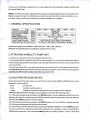
. GENERAL SPECIFICATIONS
ko)
Caoacitv
Maximum Fork Heioht
Minimum Fork Heioht
Fork Lenoth
(mm
Width Overall Forks
lndividual Fork Width
Load Wheel Diameter (mn
Steerino Wheel Diameter (mm)
2000
2000
2500
2500
3000
3000
200(or190'l
85(or75)
1150
I 1220 I 1150 I 1220.1 1150 I
1220
450t 520 /550/685
160
A 8Ox70(ot A 74x70) Nylon, Polvurethane
Q
20ObrA 180) Nvlon, Polyurethane, Rubber
Specialfork lengths are available in 800, 900, 950, 1000, 1500, 2000mm.
Materials and specifications are subject to change without notice-
2. ATTACHING HANDLE TO PUMP UNIT
2.1 Remove 3 bolts (D611) from the handle bracket (D151).
2.2 Set handle (D6'10A, D6108 or D610AS) on the bracket (D151), notice to allow the chain (D612)
and the adjusting bolts (D614) assembly to pass through thetole in the center of the bracket (D1 51 )
and shaft (D1 53).
2.3 lnsert the 3 bolts (D6'll ) through the handle into the bracket (D151), then tighten them securely.
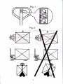
2.4 Raise the lever plat (Dl32) and insert the adjusting bolt (D614) into the front slot, keeping the
adjusting nut (D615) on the undersideofthe leyer plat (D132).
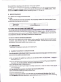
3.ADJUSTING RELEASE DEVICE
On the draw-bar of this pallet truck, you can find the control handle (D608 or D608S) which can be
adiusted in three positions :
Raise
Drive
. Lower
- handle down
- handle in center position
- handle up, the lever moves back the drive position when releasedlf howeverthey have been changed, you can adjust according to the following steps:
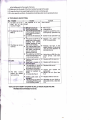
3.1 lf the forks elevate while pumping in the DRIVE position, turn the adjusting nut (D615) on the
adjusting bolt (D6'14) or adjusting screw (D133) clockwise until pumping action does not raise the
forks and the DRIVE position functions properly.
3.2 lf the forks desc€nd while pumping in the DRIVE position, turn the nut (D615) or adjusting screw
(D133) counter-clockwise until the forks do not lower.
3.3 lf the forks do not descent when the control handle (D608 or D608S) is in the LOWER position,
turnthenut(D615) oradjustingscrew(D133)clockwiseuntil raisingthe control handle(D608or
D608S) lowers the forks. Then check the DRIVE position according to item 3.'l and 3.2 to be sure