1
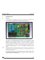
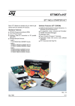
ST7 EPB User Manual Release 3.0 June 2001 Ref: DOC-ST72WIN-EPBJ/LPT INSTRUCTIONS FOR USE—WARNING This product is conform to the 89/336/EEC Directive. It complies with the ITE EN55022 standard for EMC emissions and generic 50082-1 (1992 edition) immunity standards. This product is an FCC Class-A apparatus. In a residential environment, it may cause radioelectrical disturbances. In addition, this programming board is not contained in an outer casing; consequently, it cannot be immune against electrostatic discharges (ESD). It should therefore be handled only in static safe working areas. Please refer to Appendix A: User and Work Environment Precautions on page 17 for relevant safety information USE IN LIFE SUPPORT DEVICES OR SYSTEMS MUST BE EXPRESSLY AUTHORIZED. STMicroelectronics PRODUCTS ARE NOT AUTHORIZED FOR USE AS CRITICAL COMPONENTS IN LIFE SUPPORT DEVICES OR SYSTEMS WITHOUT THE EXPRESS WRITTEN APPROVAL OF STMicroelectronics. As used herein: 1. Life support devices or systems are those which (a) are intended for surgical implant into the body, or (b) support or sustain life, and whose failure to perform, when properly used in accordance with instructions for use provided with the product, can be reasonably expected to result in significant injury to the user. 2. A critical component is any component of a life support device or system whose failure to perform can reasonably be expected to cause the failure of the life support device or system, or to affect its safety or effectiveness. Table of Contents Chapter 1: 1.1 1.2 1.3 Chapter 2: 2.1 2.2 2.3 Chapter 3: 3.1 3.2 Chapter 4: 4.1 4.2 4.3 Introduction . . . . . . . . . . . . . . . . . . . . . . . . . . . . . . . . . . . . . . . . . . 5 Overview ....................................................................................................... 5 Hardware features ........................................................................................ 6 Software features .......................................................................................... 6 Getting Started . . . . . . . . . . . . . . . . . . . . . . . . . . . . . . . . . . . . . . . . 7 Delivery checklist .......................................................................................... 7 Setting up the EPB ....................................................................................... 7 Installing the software ................................................................................... 8 How to Program . . . . . . . . . . . . . . . . . . . . . . . . . . . . . . . . . . . . . . . 9 Programming methods ................................................................................. 9 3.1.1 Installing a device for programming with the ZIF sockets ............... 9 3.1.2 Installing a device for programming using ISP or ICP modes ...... 10 A typical programming session ................................................................... 11 Hardware Features . . . . . . . . . . . . . . . . . . . . . . . . . . . . . . . . . . . . 15 Parallel port connection .............................................................................. 15 About jumpers on the ST7 EPB .................................................................. 15 Additional information about ISP mode programming ................................ 15 Appendix A: User and Work Environment Precautions . . . . . . . . . . . . . . . . . 17 Product Support . . . . . . . . . . . . . . . . . . . . . . . . . . . . . . . . . . . . . . . . . . . . . . . . . 19 Getting prepared before you call............................................................................... 19 Contact list ................................................................................................................ 19 Software updates ...................................................................................................... 20 Index . . . . . . . . . . . . . . . . . . . . . . . . . . . . . . . . . . . . . . . . . . . . . . . . . . . . . . . . . . . 21 3/22 Table of Contents 4/22 ST7 EPB User Manual 1 - Introduction 1 INTRODUCTION 1.1 Overview The ST7 EPB is a programming board kit which allows you to program ST7 microcontrollers having EPROM, EEPROM and FLASH memories. Figure 1: Typical ST7 EPB programming board The layout of the programming board included in your ST7 EPB kit varies depending on the type and package of the ST7 microcontroller you wish to program (a typical example is shown in Figure 1). However, the general programming procedure explained in this book remains the same for all boards. A complete listing of the ST7 family of programming boards, with a summary of the devices they support is given in ST7_EPB.pdf, available on the MCU on CD CDROM. Note: The ST7 EPB is meant to program small numbers of microcontrollers (i.e. prototypes in the development stage). For mass production programming, it is recommended that you use the appropriate gang programmer. The programming board is linked via the parallel port, to a host PC running the ST7 Visual Programmer software (STVP7). This software interface allows you to customize and control the programming. 5/22 1 - Introduction 1.2 ST7 EPB User Manual Hardware features A range of programming boards allow you to program all of the EPROM, EEPROM and FLASH versions of the ST7 family using onboard sockets. In addition, some EEPROM devices support In Situ Programming (ISP), and some FLASH devices support In Circuit Programming (ICP). Both ISP and ICP allow you to program the target ST7 MCU when it is already mounted on your application board, provided that you have outfitted your application board with the appropriate connector. A flex cable connects the EPB to your application board. 1.3 Software features A host PC running the ST7 Visual Programmer software (STVP7) is the control interface for the ST7 EPB. STVP7 is a graphical Windows® interface that lets you: • Read, view, edit and save executable files in the Intel® HEX and Motorola® S19 formats, generated by the Assembler, Linker or C Compiler for ST microcontrollers. • Program executable files into ST microcontrollers. • View and verify a microcontroller's memory contents. • Either create a project that defines how to program the microcontroller(s) or load the files whose contents you want to program and then execute the program. STVP7 includes a detailed online help utility. 6/22 ST7 EPB User Manual 2 GETTING STARTED 2.1 Delivery checklist 2 - Getting Started Check that your ST7 EPB kit contains the following: 2.2 • 1 ST7 EPB Eprom Programming Board (i.e. the EPB appropriate to the sales type ordered). • 1 power supply. • 1 parallel cable. • 1 MCU on CD CDROM containing the ST7 Visual Programmer (STVP7) software. • 1 10-pin HE10 type ribbon cable for ISP or ICP mode (if provided on the programming board for the sales type ordered). Setting up the EPB To set up the ST7 EPB hardware, follow these instructions: Note: 1 Shut down and power-off the host PC. 2 Connect one end of the supplied parallel cable to connector P1 of the ST7 EPB and the other end to one of the host PC’s parallel ports (LPT1 or LPT2). Be sure to use the parallel cable provided with your kit—using a longer parallel cable may cause malfunctions. Connect the cable directly between the host PC and the programming board—the insertion of additional cables or switch boxes between the host PC and the programming board may cause malfunctions. If a dongle (a hardware key required by some software packages) is already connected to the PC’s parallel port, it should not interfere with the programming board. However, if a malfunction of the board should occur, please remove the dongle and restart the above sequence. 3 Note: Power on the programming board by connecting the power supply to the programming board and to the mains. Ensure that the power supply is adapted to the mains voltage and outlet type used in your country. The board can be supplied from the integrated power supply provided with the board, or from an external +15 VDC / 0.5 A power supply. 4 Power on the host PC and install the software provided as described in the next section. 7/22 2 - Getting Started 2.3 ST7 EPB User Manual Installing the software Your ST7 EPB comes with the MCU on CD CD-ROM which contains a number of ST7 software tools. These tools are compatible with Windows® 95, 98, 2000 and Windows® NT® operating systems. Note: Windows® 2000 and NT® users must have administrator privileges to install the ST7 Visual Programmer. To install and setup the ST7 software tools, follow these steps: 1 Close all other open applications on your Windows desktop. 2 Insert the MCU on CD into your CD-ROM drive. The CD-ROM’s autorun feature will open up a welcome screen on your PC. If the autorun feature does not work, use Windows® Explorer to browse to the CD-ROM’ s root folder, and doubleclick on Welcome.exe. 3 Select Install Your Development Tools from the list of options. A new screen will appear listing the different families of STMicroelectronics MCUs. 4 Use your mouse to place the cursor over the ST7 Tools option. Choose ST Tools, then ST7 Toolchain from the lists that appear. 5 The install wizard will be launched. Follow the instructions that appear on the screen. You can choose to install the complete toolchain (i.e. the appropriate version of STVD7, the ST7 Visual Programmer and the Assembler-Linker) for each type of development tool (Development Kit, HDS2 or EMU3 emulators or simulator), or perform a customized installation. If you choose a customized installation, you can choose to install only the ST7 Visual Programmer (STVP7). The installation is now complete. You will be prompted to reboot your computer. You should do so before launching the ST7 Visual Programmer (described in Chapter 3: How to Program on page 9). 8/22 ST7 EPB User Manual 3 HOW TO PROGRAM 3.1 Programming methods 3 - How to Program Your ST7 EPB programming board is provided with at least one Zero Insertion Force (ZIF) socket which allows the programming of packaged MCUs. In addition to classic MCU programming using ZIF sockets, some EEPROM devices support In Situ Programming (ISP), and some FLASH devices support In Circuit Programming (ICP). Both ISP and ICP allow you to program the target ST7 MCU when it is already mounted on your application board, provided that you have outfitted your application board with the appropriate connector. A flex cable connects the EPB to your application board. Here we describe how to connect your device for programming using these methods. 3.1.1 Installing a device for programming with the ZIF sockets This section gives general guidelines on how to insert a device you wish to program into the ZIF sockets on the programming board. Caution: 1 Set up the EPB as described in Section 2.2 on page 7. 2 Make sure that your EPB is powered off. 3 Identify the ZIF socket for your device package on the programming board. 4 Lift the relevant ZIF socket lever and place the device into the socket with pin 1 matching the mark on the board. Take care when placing the device into a socket so as not to damage the device or the board. Forcing the MCU into the socket may result in damage to the socket. Never insert or remove devices when the programming board is powered. Devices are powered only during read or write operations. Place your device here, making sure to align pin 1 on the device with the arrow on the programming board ZIF Socket 1 lever 9/22 3 - How to Program 5 Lock the device in place by lowering the lever again. 6 Power on the EPB. ST7 EPB User Manual Use the ST7 Visual Programmer to program your device—a typical programming session is described in Section 3.2 on page 11. For more detailed information about using ST7 Visual Programmer, refer to the software’s online help. 3.1.2 Installing a device for programming using ISP or ICP modes To see whether programming in ISP or ICP mode is possible for your target MCU, refer to the MCU’s datasheet, or consult ST7_EPB.pdf, installed with the ST7 Visual Programmer, and available by selecting Start>Programs>ST7 Toolchain>User Manuals. If ISP or ICP modes are supported, your target device’s datasheet will provide the connection information necessary to set up your application board for ISP or ICP programming. Once you have ensured that the ST7 EPB programming board is a type that supports ISP or ICP mode, and you have correctly set up your application board with the appropriate connector, follow these instructions: 1 Set up the EPB as described in Section 2.2 on page 7. 2 Make sure that your EPB and application board are powered off. 3 From your host PC select Start>Programs>ST7 Tool Chain>Development Tools>ST7 Visual Programmer to launch the ST7 Visual Programmer software program. 4 Connect one end of the ISP or ICP ribbon cable to the ISP or ICP 10-pin connector on the EPB and the other end to the same type of connector on your application board. 5 Switch on your application board. 6 Power on the EPB. Use the ST7 Visual Programmer to program your device—a typical programming session is described in Section 3.2 on page 11. For more detailed information about using ST7 Visual Programmer, refer to the software’s online help. 10/22 ST7 EPB User Manual 3.2 3 - How to Program A typical programming session The following instructions describe how you would typically program an ST microcontroller using ST7 Visual Programmer. Note that this is not the only way to program an ST microcontroller using ST7 Visual Programmer; for more information on how to use the ST7 Visual Programmer, click the Help command in the main menu bar. 1 Make sure that the microcontroller you want to program is correctly connected for programming, either via the ZIF socket or in ISP or ICP mode. 2 In the Configure menu, click Configure ST7 Visual Programmer (or press the button). The Configuration dialog box opens. Figure 2: Configuration dialog box 3 From the Hardware list, select the hardware you are using. 4 From the Port list, select the parallel port on the host PC to which the EPB or DVP is connected. Only the ports that are compatible with the selected hardware are listed. 5 From the Programming mode list, select the programming mode you want to use. Programming modes available depend upon the hardware you have, and can include: 11/22 3 - How to Program ST7 EPB User Manual - Socket — This option means that you wish to program your target ST7 MCU using one of the sockets provided on the EPB or DVP. - ISP — This option is only available with certain DVPs and EPBs. Choose this option if you wish to use In Situ Programming to program a device already mounted on your application board via an flex cable connection between the DVP/EPB and your application board. - ICP — Only available for FLASH devices. Choose this option if you wish to use In Circuit Programming to program a device already mounted on your application board via an flex cable connection between the EPB and your application board. 6 From the Device list, select the ST7 microcontroller you want to program. 7 Click OK to save your changes and close the dialog box. 8 In the STVP7 main window, use the tab menu to select the memory area that you wish to program (for example, PROGRAM MEMORY, DATA MEMORY or OPTION BYTE). 9 Click on Open in the File menu (or press the appears. button). The Open dialog box Figure 3: Open dialog box 10 Browse to where you have saved the file holding the data you want to program, and then select it. 12/22 ST7 EPB User Manual 3 - How to Program 11 Click on Open. When the file is loaded, the Output area displays file checksum and device checksum. 12 To open other memory area data files, repeat steps [8] to [11], selecting the appropriate memory area tab for each data file. 13 Check that the ST7 microcontroller memory has not already been programmed: in the STVP7 main window, click on Blank-Check>All tabs. 14 Execute the programming session: in the STVP7 main window, click on All tabs in the Program menu (or press the button). 15 Check that the programing session was successfully completed: in the STVP7 main window, click on All tabs in the Verify menu (or press the button). 13/22 3 - How to Program 14/22 ST7 EPB User Manual ST7 EPB User Manual 4 HARDWARE FEATURES 4.1 Parallel port connection 4 - Hardware Features The ST7 EPB communicates with your host PC (running STVP7) via a parallel port connection. Most communication failures between the host PC running STVP7 and your programming board stem from problems in the parallel port connection. To prevent communication problems, when setting up your parallel port connection, ensure that: 4.2 • the parallel port of your PC has been configured (in the BIOS settings) with either the Centronics, EPP, ECP or bidirectional parallel port configuration. • you use the parallel cable provided with your kit—using a longer parallel cable may cause malfunctions. • connect the cable directly between the host PC and the programming board— the insertion of additional cables or switch boxes between the host PC and the programming board may cause malfunctions. • you remove any parallel port dongles. About jumpers on the ST7 EPB There are two jumpers, labelled JP2 and JP3, located on the following ST7 EPBs: • ST7MDT1-EPB2 • ST7MDT2-EPB2 • ST7MDT6-EPB2 • ST7MDT7-EPB2 These jumpers are present for manufacturing testing only. Use of these jumpers could permanently damage the programming board! 4.3 Additional information about ISP mode programming Before programming the OSCx option bits, make sure you have chosen the right options configuration. The OSCx option bits are very important. If you program the wrong OSCx option bits, depending on your hardware configuration, you may not be able to reprogram the device in ISP mode. 15/22 4 - Hardware Features 16/22 ST7 EPB User Manual ST7 EPB User Manual Appendix A: User and Work Environment Precautions APPENDIX A: USER AND WORK ENVIRONMENT PRECAUTIONS The following precautions are recommended when using the programming board: • Any tester, equipment, or tool used at any production step or for any manipulation of semi-conductor devices should have its shield connected to ground. • Your programming board should be placed on a conductive table top, made of steel or clean aluminum or covered by an antistatic surface (superficial resistivity equal to or higher than 0.5 MΩ/cm2), grounded through a ground cable (conductive cable from protected equipment to ground isolated through a 1 MΩ resistor placed in series). All manipulation of finished goods should be made at such a grounded worktable. • The worktable should be free of all non-antistatic plastic objects. • An antistatic floor covering grounded through a conductive ground cable (with serial resistor between 0.9 and 1.5 MΩ) should be used. • It is recommended that you wear an antistatic wrist or ankle strap, connected to the antistatic floor covering or to the grounded equipment. • If no antistatic wrist or ankle strap is worn, before each manipulation of the powered-on programming board, you should touch the surface of the grounded worktable. • It is recommended that antistatic gloves or finger coats be worn. • It is recommended that nylon clothing be avoided while performing any manipulation of parts. 17/22 Appendix A: User and Work Environment Precautions 18/22 ST7 EPB User Manual ST7 EPB User Manual Product Support PRODUCT SUPPORT If you experience any problems with this product or if you need spare parts or repair, contact the distributor or ST sales office where you purchased the product. Getting prepared before you call Collect the following information about the product before contacting ST or your distributor: 1 Name of the company where you purchased the programmer kit. 2 Date of purchase. 3 Order Code: Refer to the side of your programmer kit box. The order code will depend on the region for which it was ordered (i.e. the UK, Continental Europe or the USA). 4 Serial Number: The serial number is located on a label on the programming board. 5 Target Device: The sales type of the ST7 microcontroller you are using in your development. Contact list Note: For American and Canadian customers seeking technical support the US/Canada is split in 3 territories. According to your area, contact the following sales office and ask to be transferred to an 8-bit microcontroller Field Applications Engineer (FAE). Canada and East Coast STMicroelectronics Lexington Corporate Center 10 Maguire Road, Building 1, 3rd floor Lexington, MA 02421 Phone: 781-402-2650 Mid West STMicroelectronics 1300 East Woodfield Road, Suite 410 Schaumburg, IL 60173 Phone: 847-517-1890 19/22 Product Support ST7 EPB User Manual West coast STMicroelectronics, Inc. 30101 Agoura Court Suite 118 Agoura Hills, CA 91301 Phone: 818-865-6850 Europe France (33-1) 47407575 Germany (49-89) 460060 U.K. (44-1628) 890800 Asia/Pacific Region Japan (81-3) 3280-4120 Hong-Kong (852) 2861 5700 Sydney (61-2) 9580 3811 Taipei (886-2) 2378-8088 Software updates You can get software updates from the ST Internet web site http://mcu.st.com. For information on firmware and hardware revisions, call your distributor or ST using the contact list given above. 20/22 Index D O delivery checklist................................................. 7 OSCx option bits............................................... 15 overview ............................................................. 5 E P EPB setting up .................................................... 7 F finished goods manipulation of.......................................... 17 safety requirements .................................. 17 H hardware features ....................................................... 6 setting up .................................................... 7 supplied....................................................... 7 I In Circuit Programming (ICP).............................. 6 In Situ Programming (ISP) .................................. 6 programming in ISP mode ........................ 10 warning about OSCx option bits ............... 15 J JP2, JP3............................................................ 15 jumpers ............................................................. 15 M parallel connection restrictions/requirements ...................... 7, 15 parallel port configuration............................................. 15 connection to PC ...................................... 15 troubleshooting......................................... 15 power supply restrictions/requirements ............................ 7 S setting up the EPB.............................................. 7 software features....................................................... 6 installing...................................................... 8 updates..................................................... 20 ST7 Visual Programmer (STVP7) configuring................................................ 11 installing...................................................... 8 launching .................................................... 9 typical programming session .................... 11 support contact numbers for.................................. 19 for development kit ................................... 19 information required.................................. 19 Z ZIF sockets ......................................................... 9 MCU on CD......................................................... 8 21/22 2 2 Information furnished is believed to be accurate and reliable. However, STMicroelectronics assumes no responsibility for the consequences of use of such information nor for any infringement of patents or other rights of third parties which may result from its use. No license is granted by implication or otherwise under any patent or patent rights of STMicroelectronics. Specifications mentioned in this publication are subject to change without notice. This publication supersedes and replaces all information previously supplied. STMicroelectronics products are not authorized for use as critical components in life support devices or systems without the express written approval of STMicroelectronics. The ST logo is a registered trademark of STMicroelectronics. Intel® is a U.S. registered trademark of Intel Corporation. Microsoft®, Windows® and Windows NT® are U.S. registered trademarks of Microsoft Corporation. 2001 STMicroelectronics - All Rights Reserved. Purchase of I2C Components by STMicroelectronics conveys a license under the Philips I2C Patent. Rights to use these components in an I2C system is granted provided that the system conforms to the I2 C Standard Specification as defined by Philips. STMicroelectronics Group of Companies Australia - Brazil - China - Finland - France - Germany - Hong Kong - India - Italy - Japan - Malaysia - Malta - Morocco - Singapore - Spain Sweden - Switzerland - United Kingdom - U.S.A. http://www.st.com