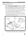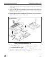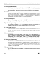
1
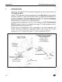
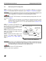
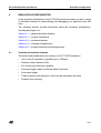
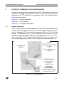
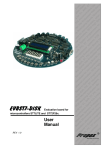
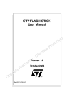
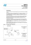
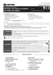
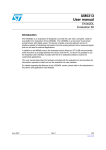
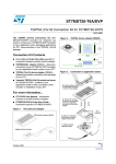
ST7-DVP3 Emulator
User Manual
Release 1.3
November 2004
Ref: DOC-ST7-DVP3
INSTRUCTIONS FOR USE—WARNING
This product is conform to the 89/336/EEC Directive. It complies with the ITE EN55022 (1998 edition)
standard for EMC emissions and the 55024 (1998 edition) immunity standards.
This product is an FCC Class-A apparatus. In a residential environment, it may cause
radioelectrical disturbances.
In addition, this emulator is not contained in an outer casing; consequently, it cannot be immune against
electrostatic discharges (ESD). Please refer to Appendix A EMC Conformity and Safety Requirements
on page 29 for relevant safety information.
USE IN LIFE SUPPORT DEVICES OR SYSTEMS MUST BE EXPRESSLY AUTHORIZED.
STMicroelectronics PRODUCTS ARE NOT AUTHORIZED FOR USE AS CRITICAL COMPONENTS IN
LIFE SUPPORT DEVICES OR SYSTEMS WITHOUT THE EXPRESS WRITTEN APPROVAL OF
STMicroelectronics. As used herein:
1. Life support devices or systems are those
which (a) are intended for surgical implant into
the body, or (b) support or sustain life, and whose
failure to perform, when properly used in
accordance with instructions for use provided
with the product, can be reasonably expected to
result in significant injury to the user.
2. A critical component is any component of a life
support device or system whose failure to
perform can reasonably be expected to cause the
failure of the life support device or system, or to
affect its safety or effectiveness.
Table of Contents
Chapter 1:
1.1
1.2
1.3
Chapter 2:
2.1
2.2
2.3
Chapter 3:
3.1
3.2
Chapter 4:
4.1
4.2
4.3
4.4
4.5
Chapter 5:
5.1
5.2
5.3
Introduction . . . . . . . . . . . . . . . . . . . . . . . . . . . . . . . . . . . . . . . . . . 4
About the user manuals... ............................................................................. 5
Host PC system requirements ...................................................................... 6
Getting assistance ........................................................................................ 6
Getting Started with ST7-DVP3 . . . . . . . . . . . . . . . . . . . . . . . . . . . 7
Delivery checklist .......................................................................................... 7
Quick set up for emulation configuration ................................................... 10
Quick set up for ICC configuration .............................................................. 11
Connectivity . . . . . . . . . . . . . . . . . . . . . . . . . . . . . . . . . . . . . . . . . 12
Parallel port ................................................................................................. 13
USB port ..................................................................................................... 14
Emulation Configuration . . . . . . . . . . . . . . . . . . . . . . . . . . . . . . . 15
Overview of emulation features .................................................................. 15
System architecture .................................................................................... 16
Hardware features ...................................................................................... 17
Changing configurations ............................................................................. 22
Emulator functional limitations and discrepancies ...................................... 22
In-circuit Communication Configuration . . . . . . . . . . . . . . . . . . 23
System architecture .................................................................................... 23
ICC connection ........................................................................................... 24
Changing configurations ............................................................................. 27
Appendix A: EMC Conformity and Safety Requirements . . . . . . . . . . . . . . . . 29
Appendix B: Changing the TEB . . . . . . . . . . . . . . . . . . . . . . . . . . . . . . . . . . . . 30
Appendix C: Troubleshooting . . . . . . . . . . . . . . . . . . . . . . . . . . . . . . . . . . . . . . 32
Appendix D: Glossary . . . . . . . . . . . . . . . . . . . . . . . . . . . . . . . . . . . . . . . . . . . . 35
Product Support . . . . . . . . . . . . . . . . . . . . . . . . . . . . . . . . . . . . . . . . . . . . . . . . . 39
Index . . . . . . . . . . . . . . . . . . . . . . . . . . . . . . . . . . . . . . . . . . . . . . . . . . . . . . . . . . . 42
3/44
Introduction
1
ST7-DVP3 Emulator User Manual
INTRODUCTION
Thanks for choosing ST7! This manual will help you set up and start using your
ST7-DVP3 emulator.
The ST7-DVP3 emulator is the latest generation in the DVP series of development
emulation systems. It offers start-to-finish control of application development by
providing emulation, in-circuit programming (ICP) and in-circuit debugging
(ICD) capability in an economical, modular package.
In the emulation configuration, your ST7-DVP3 emulator and ST7 Visual Develop
(STVD7) software, allow you to emulate your target ST7 while connected to your
application board in place of your ST7.
In the in-circuit communication (ICC) configuration, your DVP3 emulator and
STVD7 allow you to debug your application while it runs on your ST7, and to
program your ST7 microcontroller with ST7 Visual Programmer (STVP7).
In-Circuit Communication
(ICC) Configuration
Host PC running
STVD7 or STVP7
STVD7 or STVP7
ST7-DVP3 emulator
ICC connection
ST7 in your application
Connects via
Parallel port
or USB port
ST7-DVP3 emulator
ICC connection
ST7
Emulation Configuration
STVD7
ST7-DVP3 emulator
Probe and adapters
Probe
Figure 1: ST7-DVP3 emulator configurations
4/44
1
ST7-DVP3 Emulator User Manual
1.1
Introduction
About the user manuals...
This manual will help you set up your ST7-DVP3 emulator and connect it to your
PC. Here, you will find:
•
Quick set up instructions for the emulation and ICC configurations
•
Detailed hardware information
•
A trouble shooting guide for your development kit
For information about the hardware and software intended for use with your
development kit, refer to the following documents that are included with it:
STVD7 Visual Develop online help- build and debug your application software
ST7 Visual Programmer online help - program your MCU
ST7xxxx-DVP3 Probe User Guide - connect the TEB to your application board
ST7xxxx Datasheet - includes information about emulation and ICC connection
that are specific to your MCU
1.1.1
Revision history
Date
Revision
Description
Nov 2002
1.1
• Updated USB port configuration information, Section 3.2.
Dec 2003
1.2
• Removed STVD7 and STVP7 software installation and use
instructions.
• Added quick set up instructions, Section 2.2 andSection 2.3.
Nov 2004
1.3
• Added support of in-circuit debugging, Section 1 and
Section 5.
• Added revision history table, Table 1.
• Updated Section 3 to align menu references and command
sequences with STVD7 3.0.
• Added in-circuit communication (ICC) connection
requirements for application boards, Section 5.2.
• Added note regarding Hardware test failure due to changes
in target device memory mapping, Section C.3.
Table 1: ST7-DVP3 User Manual Revision History
5/44
Introduction
1.2
ST7-DVP3 Emulator User Manual
Host PC system requirements
Both hardware and software components of the ST7-DVP3 emulator have been
designed to work with PCs meeting the following requirements:
•
One of the following operating systems: Microsoft® Windows® 98, 2000,
Millennium, NT® or XP®.
•
Intel® Pentium (or compatible) processor with minimum speed of 133 MHz.
•
Minimum RAM of 32 MB (64 MB recommended).
•
50 MB of free hard disk space to install all of the ST7 tools.
Note:
Windows® 2000, NT® and XP® users must have administrator privileges to install STVD7.
1.3
Getting assistance
For more information, application notes, FAQs and software updates on all the ST
microcontroller families, check out the CD-ROM or our website:
mcu.st.com
For assistance on all ST microcontroller subjects, or if you need help with using
your development kit, use the contact list provided in Product Support on page 39.
We’ll be glad to help you!
6/44
ST7-DVP3 Emulator User Manual
2
Getting Started with ST7-DVP3
GETTING STARTED WITH ST7-DVP3
The ST7-DVP3 emulator can be configured for emulation or in-circuit programming
(ICP) and in-circuit debugging of your ST7. To help you get started, the following
sections provide:
2.1
•
Section 2.1 — a check list of components included in your kit
•
Section 2.2 — quick set up instructions for the emulation configuration
•
Section 2.3 — quick set up instructions to in-circuit debug and in-circuit
program in the ICC configuration
Delivery checklist
The ST7-DVP3 emulator is delivered with (refer to Figure 2):
1
The ST7-DVP3 development board, which consists of one DVP3 Main
Emulation Board (MEB) mounted with the Target Emulation Board (TEB)
corresponding to your ST7 microcontroller
2
One DC power supply, one ferrite clip and three power supply plug extensions
for standard North American, continental European and UK power outlets
3
One parallel port cable with ferrite bead to connect the emulator to your PC
4
One USB cable to connect the emulator to your PC
5
One ICC cable for in-circuit communication connections
6
One passive probe with the device adapters and cables needed to connect your
ST7-DVP3 emulator to your application board (for details refer to the ST7xxxxDVP3-Probe User Guide provided).
(2)
(1)
TEB
MEB
Figure 2: Parts delivered with the ST7-DVP3 emulator (not to scale)
7/44
2
Getting Started with ST7-DVP3
ST7-DVP3 Emulator User Manual
(3)
(4)
(5)
(6)
Type and number of probes
and adapters depends on
connection kit you have
ordered - for more information
refer to your ST7xxxx-DVP3
Probe User Guide.
Figure 2: Parts delivered with the ST7-DVP3 emulator (not to scale)
All ST7-DVP3 emulators come with the following documentation.
8/44
•
This manual.
•
ST7xxxx-DVP3 Probe User Guide, specific to the type of ST7-DVP3 emulator
you have ordered
•
ST7 ASM Quick Reference Guide
•
ST Product and Tool Selection Guide
•
The “Microcontroller Development Tools” CD-ROM, with all the software
you need to run your ST7-DVP3 emulator, including:
-
The ST7 Visual Develop (STVD7) software , which includes an online help
file to get you started.
-
The ST7 Visual Programmer (STVP7) software, which includes an online
help file to get you started.
ST7-DVP3 Emulator User Manual
-
Getting Started with ST7-DVP3
The ST7 Assembler-Linker software with user manual in Adobe®
Acrobat®PDF format.
•
Software demonstration packages, including C compilers and toolchains by
Cosmic and Metrowerks.
The “ST Microcontrollers Mini-ROM” with a presentation of the ST7 family of
microcontrollers.
9/44
Getting Started with ST7-DVP3
2.2
ST7-DVP3 Emulator User Manual
Quick set up for emulation configuration
Voltage selector switch
STEP 1: Connect your emulator to your host
PC via parallel or USB port.
For more details refer
Connectivity on page 12.
Use USB or parallel
connection
to
Chapter 3:
Warning: Never have an application running
when you set the operating voltage.
Setting it to 3.3V while an
application is running at 5V
can seriously damage the emulator.
!
STEP 2: Select the operating voltage, either
3.3V or 5V, with the voltage selector switch.
Figure 3: Connect your PC
Caution:
Before making hardware connections,
ensure that both the emulator and your
application board are powered OFF
STEP 3: Plug the flat cables into the
connectors on the TEB. Connect the probe to
your application in place of your MCU.
For detailed instructions refer to your
ST7xxxx-DVP3 Probe User Guide.
Power supply cable
ST7-DVP3 TEB
Flat cables
Adapter
STEP 4: Connect the ferrite clip to the power
supply cord between the power supply and
and your emulator.
Figure 4: Connect your application
Warning: Never power on your application board while your emulator is powered off—this can
seriously damage your emulator. When powering up, always turn on your emulator
first. When powering off, always power off your application first.
!
STEP 5: Connect the power supply to your ST7-DVP3 emulator. For more information, refer
to Section 4.3.2: Power supply on page 17.
STEP 6: Power up your ST7-DVP3 emulator.
STEP 7: Power up your application.
10/44
ST7-DVP3 Emulator User Manual
2.3
Getting Started with ST7-DVP3
Quick set up for ICC configuration
STEP 1: Connect your emulator to your host PC via parallel or USB port, as shown in
Figure 3. For more details about PC connection, refer to Chapter 3: Connectivity on page 12.
Warning: Never have an application running when you set the operating voltage. Setting it to 3.3V
while an application is running at 5V can seriously damage the emulator.
!
STEP 2: Switch the ST7-DVP3 emulator to the selected operating voltage, either 3.3V or 5V,
as shown in Figure 3.
Note:
In order to use the ICC connection, you must design your application board with an HE10
connector linked to your target microcontroller. The pins connected to the HE10 connector
must use a signal voltage of 3.3 or 5 V. For more information refer to Section 5.2: ICC
connection on page 24.
STEP 3: To connect to the target MCU, plug
the ICC cable into the ICC connector on the
ST7-DVP3 emulator and the HE10 connector
on your application board.
STEP 4: Connect the ferrite clip to the power
supply cord between the supply and your
ST7-DVP3 emulator.
STEP 5: Connect the power supply to your
emulator. For power supply information,
refer to Section 4.3.2: Power supply on
page 17.
Power supply cable
Flat cables and
adapter (not used)
ICC cable
ST7
HE10 connector on
application board
Figure 5: Connect your application
Warning: Never power on your application board while your emulator is powered off—this can
seriously damage your emulator. When powering up, always turn on your emulator
first. When powering off, always power off your application first.
!
STEP 6: Power up your ST7-DVP3 emulator.
STEP 7: Power up your application.
11/44
Connectivity
3
ST7-DVP3 Emulator User Manual
CONNECTIVITY
The ST7-DVP3 emulator provides two possible connections to the host PC:
parallel and USB port.
When you start your emulation or programming sessions, you will have to set the
connection type in STVD7 or STVP7. In STVD7, set the port in the Debug
Instrument Settings window (Debug Instrument>Target Settings). When
programming your ST7 with STVP7, set the port in the Configuration window
(Configure>Configure ST7 Visual Programmer). For more information refer to
your software's online help.
The following sections provide you with information about supported connections,
as well as how to connect your PC via:
•
Section 3.1 – Parallel port
•
Section 3.2 – USB port
1
2
Connect via parallel
port or USB port
Set the connection type in
STVD7 or STVP7
Figure 6: Parallel and USB port connections
12/44
ST7-DVP3 Emulator User Manual
3.1
Connectivity
Parallel port
Your ST7-DVP3 emulator supports the parallel port connection modes listed in
Table 2, for the emulation and the in-circuit communication configurations.
Operating
Systems
Compatible Parallel Port
Modes
Windows® 98,
Millennium, NT®4,
2000, XP®
ECP1, Bidirectional, Compatible,
SPP, Nibble, Centronics or EPP.
Configuration
Emulation,
In-circuit Communication
Table 2: Supported parallel port connection modes
1) ECP mode is normally chosen as a default mode as it provides the best performance.
3.1.1
Connecting to the parallel port
To connect your ST7-DVP3 emulator to your PC, connect one end of the parallel
cable to your development kit’s 25-pin SUB-D connector (see Figure 6). Connect
the other end of the parallel cable to one of the PC’s parallel ports (LPT1 or LPT2).
Be sure to use the parallel cable provided with your emulator. Using a longer
parallel cable may cause emulator malfunctions. The use of switch boxes between
your PC’s parallel port connector and the emulator is not recommended.
3.1.2
Changing the parallel port set up
Under certain circumstances, you may receive the following error message:
"Connection Error (LPT1/LPT2): Interconnection failure.
Verify your input/output cable."
This may mean that the setup of the LPT1 or LPT2 port on your PC is not
compatible with your emulator. To set up the port correctly:
1
Shut down and restart your PC in order to enter the BIOS setup.
2
Follow the messages displayed on the screen and when prompted, press the
key required to enter the BIOS setup (usually a function key or the ESC key).
3
Select the parallel ports menu. (This may be listed under I/O ports.)
4
Change the Mode of the LPT port that you have chosen for your emulator (i.e.
either LPT1 or LPT2) to one of the compatible modes listed in Table 2 on
page 13.
5
Save your changes and exit the BIOS setup.
13/44
Connectivity
3.2
ST7-DVP3 Emulator User Manual
USB port
Your ST7-DVP3 emulator supports USB connection in both the emulation and incircuit communication configurations, when using Windows®98, Millennium, 2000
and XP®.
3.2.1
Connecting to the USB port
For USB port connections, plug the USB cable into the emulator’s USB port (as
shown in Figure 6) and connect the other end into the PC’s USB port. Once
connected and powered-on for the first time, your PC will automatically look for a
USB device driver.
14/44
ST7-DVP3 Emulator User Manual
4
Emulation Configuration
EMULATION CONFIGURATION
In the emulation configuration, the ST7-DVP3 emulator provides you with a range
of emulation features to make building and debugging your application fast and
easy.
The following sections provide information about the emulation configuration,
including descriptions of:
Section 4.1 — general emulation features
Section 4.2 — system architecture
Section 4.3 — hardware features
Section 4.4 — changing configurations
Section 4.5 — product limitations and discrepancies
4.1
Overview of emulation features
The features described below are common to all ST7-DVP3 emulators.
•
Link to host PC possible via parallel port or USB port
•
Emulator status indicator LEDs
•
512 record trace with filter capability
•
One input trigger, which can be recorded in the trace
•
One output trigger
•
Three analyzer probe input pins, which can be recorded in the trace
•
External clock sourcing
15/44
Emulation Configuration
4.2
ST7-DVP3 Emulator User Manual
System architecture
The ST7-DVP3 emulator is composed of the following elements:
•
ST7 Visual Develop (STVD7) software runs on your host PC, allowing you to
configure and control your emulator, and debug your application.
•
The Main Emulation Board (MEB) is the hardware component that provides
the communication links between the host PC and the ST7xxxx-DVP3 TEB.
The MEB connects to the host PC through either USB or parallel port
connection, and is powered by an external power supply.
•
The Target Emulation Board (TEB) is the hardware component that contains
the emulation firmware needed to emulate a family of MCUs. It also permits the
connection to your application board (see ST7xxxx-DVP3 Probe User Guide).
•
Adapters and connectors allow you to connect your emulator to your
application board in place of your ST7 microcontroller (see ST7xxxx-DVP3
Probe User Guide).
Adapter(s) and
Sockets allow
connection to your
application board
Target Emulation Board
(TEB) & flat cables- the TEB
is specific to an MCU or family
of MCUs
Main
Emulation
Board
(MEB) - the MEB is common
to all DVP3 development kits
Host PC
Running ST7 Visual
Develop (STVD7)
USB or Parallel port
connection
Figure 7: Emulation configuration
16/44
ST7-DVP3 Emulator User Manual
4.3
Emulation Configuration
Hardware features
While target emulation boards will vary from one version to another, all ST7-DVP3
development boards offer some standard features that will help you debug your
application, including voltage selection, analyzer probe input pins, input/output
triggers and external clock connection. These features and common
characteristics of the ST7-DVP3 development board are described in this section.
Probe connectors
Three Status LEDs:
Red, Yellow and Green
TEB
Voltage selection
switch
MEB
3 Analyzer probe
input pins
EXTCLK
Power Supply
connection
Parallel
Port
Input/Output
trigger pins
USB Port
Figure 8: General layout of ST7-DVP3
4.3.1
Emulation status LEDs
There are three LEDs on the ST7-DVP3 development board, which indicate
emulator status during debugging (seeFigure 8):
4.3.2
•
Reset (Red) — indicates that the emulator is being reset, or flashes slowly
when the emulator is in Wait for Interrupt mode.
•
Halt (Yellow) — indicates when the emulation chip is in Halt mode.
•
Run (Green) — indicates when the emulator is running your application.
Power supply
The emulator’s power supply plugs into the power supply connector on the MEB
(see Figure 8). When you connect the power supply, be sure to:
17/44
Emulation Configuration
ST7-DVP3 Emulator User Manual
1
Ensure that the operating voltage of the ST7-DVP3 emulator (110 Volts/
220 Volts) matches that which is indicated on the label of your power supply.
Contact your dealer if this voltage does not correspond to your mains.
2
Install the provided ferrite clip on the cord running between the emulator and the
power supply, approximately 10 cm from your emulator (see Figure 9).
1
Ferrite
Power cable
2
3
ST7-DVP3 emulator
10 cm
Figure 9: Connecting the ferrite clip
3
4.3.3
Plug the power supply into the mains using the supply cable provided.
Application voltage selector switch
Before you connect your application board to your emulator, you must set the
operating voltage to that which corresponds to the designed operating voltage of
your application board. This is done with the voltage selector switch. The switch is
located on the main emulation board near the status LEDs (see Figure 8). It allows
you to select an operating voltage of either 3.3V or 5V.
Caution:
18/44
Failure to select the correct voltage for your application board can result in damage to your
emulator or your application board.
ST7-DVP3 Emulator User Manual
4.3.4
Emulation Configuration
Input and output triggers
There are two trigger pins on the ST7-DVP3 development board, TRIGOUT and
TRIGIN (see Figure 8), that permit you to send and receive trigger signals. This
capability will help you ensure that the ST7 microcontroller’s activities are wellsynchronized with other devices in your application. With STVD7, these triggers
allow you to:
4.3.4.1
•
Generate a break in the execution of your application. When combined with
trace recording, it is possible to track the sequence of events that precede and
follow the reception of an external signal.
•
Generate an output trigger signal to be sent upon the occurrence of a
hardware event. Hardware events are explained in detail in the STVD7 User
Manual. Trace recording can also be synchronized around a hardware event.
Hardware events and the external output trigger (TRIGOUT)
The ST7-DVP3 development board features a TRIGOUT pin from which a signal
can be sent out. See Figure 8 for the location of the TRIGOUT pin.
The sending of trigger signals is controlled by hardware events. There are three
types of hardware event:
•
Event On (EVT_ON): Upon a memory read or write at a specified address, or
the occurrence of specified variable, the trigger output signal is set high. You
can also choose to have trace recording begin simultaneously.
•
Event Off (EVT_OFF): Upon a memory read or write at a specified address, or
the occurrence of specified variable, the trigger output signal is set low. You
can use this to end trace recording.
•
Event Hit (EVT_HIT): Upon a memory read or write at a specified address, or
the occurrence of specified variable, the trigger output signal is set high for the
cycles in which one particular address is accessed.
19/44
Emulation Configuration
ST7-DVP3 Emulator User Manual
Figure 10 shows how the output trigger signal can be controlled using the above
hardware event type.
2nd
1st
EVT_OFF
EVT_OFF
EVT_ON and
EVT_OFF
1st EVT_ON
hardware event
2nd
EVT_ON
3rd
EVT_OFF
3rd
EVT_ON
period of time between event
provoking pulse action
Event Hit
pulse lasting one
processor cycle
Figure 10: Output trigger action modes
For information on how to insert hardware events, refer to the STVD7 User
Manual.
4.3.4.2
Input trigger (TRIGIN)
The ST7-DVP3 development board provides a special inlet, TRIGIN, that can be
used to transmit a signal to stop the execution of your application upon the
occurrence of an external event (Break on TRIGIN). With this feature, the
reception of a rising edge signal from the TRIGIN pin stops the program after the
execution of the current instruction.
20/44
ST7-DVP3 Emulator User Manual
Emulation Configuration
A schematic diagram is shown below:
FCPU
Opcode Fetch
TRIGIN
TRIGIN active on rising edge
Application running
Application stopped- monitor running
Figure 11: TRIGIN signal
4.3.5
External clock connection
The ST7-DVP3 development board provides and external clock connection,
labelled EXTCLK (see Figure 8). If your ST7 microcontroller application requires
the use of a clock external to the microcontroller, you should connect the external
clock to this pin.
4.3.6
Analyzer input connections
The ST7-DVP3 development board provides three analyzer probe input
connections (PROBE 0, 1 and 2). These connectors allow you to use external
signals (TTL level), coming either from your application or another external device,
while debugging your application. These signals can be recorded in the trace.
21/44
Emulation Configuration
4.4
ST7-DVP3 Emulator User Manual
Changing configurations
Your ST7-DVP3 emulator is designed to connect to your application board either in
place of your ST7 via the probe (TEB, flat cables, adapters and socket), or the ICC
connection which is relayed to the ST7 on your application board. For more
information about the probe connection, refer to your ST7xxxx-DVP3 Probe User
Guide.
When using your emulator you must only use one connection at a time. If you
switch from one connection to another, follow the procedure outlined below.
Switching from probe connection to the ICC connection
1
Switch off the application board.
2
Disconnect the power to the ST7-DVP3 development board.
3
Unplug the probe from your application board.
4
Install the target MCU in its socket on the application board.
5
Plug one end of the ICC cable into the ICC connector on your ST7-DVP3
development board, and plug the other end into the HE10 connector on your
application board.
6
Reconnect the power supply for the ST7-DVP3 development board.
7
Switch on the power for the application board.
4.5
Emulator functional limitations and discrepancies
4.5.1
Limitations and discrepancies for specific MCUs or families of MCUs
Specific MCUs of families of MCUs may present certain limitations or
discrepancies. You will find information about these specific limitations in STVD7’s
Discrepancies window. For more information refer to the STVD7 User Manual.
22/44
ST7-DVP3 Emulator User Manual
5
In-circuit Communication Configuration
IN-CIRCUIT COMMUNICATION CONFIGURATION
In the in-circuit communication configuration, the ST7-DVP3 emulator provides the
capability to to debug your application as it runs on your ST7 and program your
application to the ST7 soldered on your application board. The following sections
provide information about:
Section 5.1 — System architecture
Section 5.2 — ICC connection
Section 5.3 — Changing configurations
5.1
System architecture
The ST7-DVP3 emulator comes equipped with an In-Circuit Communication (ICC)
connector and ICC cable that allows you to take advantage of the ICC protocol for
in-circuit debugging (ICD) and in-circuit programming (ICP) on ST7s with Flash
memory. In conjunction with ST7 Visual Develop (STVD7) software, the ICC
connection makes it possible to debug your application while it runs on your ST7.
Then using STVD7, or ST7 Visual Programmer (STVP7), you can program your
final, optimized application to the ST7 on your application board (see Figure 12).
Host PC
Parallel port or
USB port
Running ST7 Visual Develop
(STVD7)
or
ST7 Visual Programmer
(STVP7)
ST7-DVP3 Emulator
with ICC connector
and cable
(Probe not used)
ICC cable &
HE10 connector
installed on application board
and relayed to your ST7.
Figure 12: ICC configuration
23/44
In-circuit Communication Configuration
ST7-DVP3 Emulator User Manual
During application development, STVD7 software running on your PC provides an
integrated development environment that allows you to debug your application
while it runs on an ST7 that has Debug Modules. To determine if your ST7 has
core debug modules, refer to your ST7xxxx Datasheet. For more information about
in-circuit debugging with STVD7, refer to the STVD7 online help provided with your
software package.
Once you’ve finalized your application, STVP7 software provides a graphical
interface for verifying memory sectors, checking the settings of the option bytes
and programming your ST7. For more information about programming with
STVP7, refer to the STVP7 online help provided with your software package. For
more information about ICC protocol related to your ST7 MCU, you can refer to
your ST7xxxx Datasheet.
5.2
ICC connection
To take advantage of ICC, you must integrate an ICC connector into your
application hardware when you start developing your application. To help you
implement ICP and ICD in the development of your application, this section
provides a summary of points you should consider when installing an ICC
connector.
To connect to your application board for ICP
and ICD, you need to install a 10-pin, HE-10
type connector (also called an ICC Connector)
and ensure the appropriate connections to your
ST7. This connector receives the ICC cable
and relays the signals required for ICP and ICD
to your ST7.
Using the ICC protocol requires that a minimum of 4 and as many as 6 pins of your
ST7 be relayed to the ICC Connector. These connection requirements are
illustrated in Figure 13, below and summarized in Figure 3.
24/44
ST7-DVP3 Emulator User Manual
In-circuit Communication Configuration
Figure 13: ICC interface
ST7 Pin
Connects to ICC
connector pin...
Function
ICCDATA
ICC input/output serial data pin
ICCDATA
ICCCLK
ICC input serial clock pin
ICCCLK
RESET
Device reset
ICCRESET
ICCSEL/VPP
Programming voltage
ICCSEL/VPP
OSC1 or OSCIN
Main clock input for external
ICCOSC
VDD
Device power supply
VDD_APPLI
(not connected)
VSS
Device power supply (ground)
GND
Table 3: ICC connection requirements
25/44
In-circuit Communication Configuration
ST7-DVP3 Emulator User Manual
Isolation of ICCDATA and ICCCLK pins
As soon as the DVP3’s ICC connector is connected to the application board, the
ICCDATA and ICCCLK pins must not be used by other application devices, even if
an ICC session is not in progress. If the application uses these pins as inputs,
isolation such as a serial resistor must be implemented to prevent other application
devices from forcing a signal on either of these pins. The application board must
not drive current in excess of 1mA.
If the ICCDATA and ICCCLK pins are only used as outputs by the application, no
signal isolation is necessary.
For ST7 without an ICCSEL pin, during normal operation the ICCCLK pin must be
pulled-up internally or externally (10KΩ pull-up required in noisy environments).
This is to avoid entering ICC mode unintentionally during a reset.
Isolation of the RESET pin
During an ICC session, you must ensure that the emulator controls the ST7’s
RESET pin so that no external reset is generated by the application. This can lead
to a conflict if the application reset circuitry signal exceeds 5mA (push-pull output
or pull-up resistor <1K). To avoid such conflicts, a Shottky diode can be used to
isolate the application reset circuit.
ICCSEL/VPP pin
The application pull-down resistor must not be lower than 10kΩ.
ICCOSC pin
The ICCOSC pin of the ICC connector must be connected to the ST7’s OSC1 or
OSCIN pin if the clock is not provided by the application, or if the application clock
source is not programmed in the option byte. This connection allows you start
communication with your ST7 for in-circuit debugging using the Start with
External Clock (Ignore Option Bytes) option in STVD7, or for in-circuit
programming using the ICP OPT Disable mode in STVP7 or STVD7. When doing
so, your emulator provides a clock source to initiate communication with the ST7.
Your ST7-DVP3 emulator provides a clock source at a frequency of 8 MHz.
For ST7 devices with multi-oscillator capability, when the ICCOSC pin is
connected, the OSC2 pin should be grounded.
If your application provides a clock signal and you are certain that it is correctly
programmed in the ST7’s option byte, then it is not necessary to use the Start with
External Clock (Ignore Option Bytes) option when you start ICD in STVD7.
When starting ICP, you can use the ICP OPT Enable mode in STVP7 or STVD7.
26/44
ST7-DVP3 Emulator User Manual
In-circuit Communication Configuration
In this case, your application clock source provides the clock signal for initiating
communication with your ST7 and ICCOSC is not connected to your ST7.
VDD_APPLI pin
This pin is not connected. It is only used with tools that have a power supply
follower.
ICC cable
Your ST7-DVP3 emulator includes an ICC cable for connecting to the ICC
connector on your application board. The provided cable is 30cm long, however
you can use a cable up to 2 meters long. Typical characteristics for provided ICC
cable are shown in Table 4, below.
Pitch
1.27 mm
Section
Impedance
Nominal Voltage
0.09mm2
100 Ohms
300V
Max. Current
1A
Temperature
-10°C to +105° C
Table 4: Typical ICC cable characteristics
5.3
Changing configurations
Your ST7-DVP3 emulator is designed to connect to your application board either in
place of your ST7 via the probe (TEB, flat cables, adapters and socket), or the ICC
connection which is relayed to the ST7 on your application board. For more
information about the probe connection, refer to your ST7xxxx-DVP3 Probe User
Guide.
When using your emulator you must only use one connection at a time. If you
switch from one connection to another, follow the procedure outlined below.
Switching from ICC connection to the probe connection
1
Switch off the application board.
2
Disconnect the power to the ST7-DVP3 emulator.
3
Unplug the ICC cable from the HE10 connector on your application board.
4
Remove the MCU from its socket on the application board.
5
Connect the probe to your application board in place of your target MCU.
27/44
In-circuit Communication Configuration
28/44
ST7-DVP3 Emulator User Manual
6
Reconnect the power supply for the ST7-DVP3 emulator.
7
Switch on the power for the application board.
ST7-DVP3 Emulator User Manual
Appendix A EMC Conformity and Safety Requirements
APPENDIX A EMC CONFORMITY AND SAFETY REQUIREMENTS
This product respects the EMC requirements of the European guideline 89/336/
EEC under the following conditions:
•
Any tester, equipment, or tool used at any production step, or for any
manipulation of semiconductor devices, must have its shield connected to
ground.
•
All provided ferrites must be attached as described in the hardware installation
instructions of the relevant user manual(s).
•
The product must be placed on a conductive table top, made of steel or clean
aluminum, or covered by an antistatic surface (superficial resistivity equal to or
higher than 0.5 MΩ/cm2), grounded through a ground cable (conductive cable
from protected equipment to ground isolated with a 1 MΩ resistor placed in
series). All manipulation of finished must be done at such a grounded
worktable.
•
The worktable must be free of all non-antistatic plastic objects.
•
An antistatic floor covering grounded through a conductive ground cable (with
serial resistor between 0.9 and 1.5 MΩ) should be used.
•
It is recommended that you wear an antistatic wrist or ankle strap, connected to
the antistatic floor covering or to the grounded equipment.
•
If no antistatic wrist or ankle strap is worn, before each manipulation of the
powered-on tool, you must touch the surface of the grounded worktable.
•
It is recommended that antistatic gloves or finger coats be worn.
•
It is recommended that nylon clothing be avoided while performing any
manipulation of parts.
•
If you are using this product under conditions where there may be blackouts or
power surges (such as during an electrical storm), it is recommended that you
isolate it by elevating it at least 10 cm above the grounded work surface using
blocks of insulating material.
29/44
Appendix B: Changing the TEB
ST7-DVP3 Emulator User Manual
APPENDIX B:CHANGING THE TEB
ST7-DVP3 emulators have a modular design that is based on two emulation
boards. The Main Emulation Board (MEB) is identical for all ST7-DVP3
emulators. The Target Emulation Board (TEB) is specific to an ST7 or a family of
ST7 microcontrollers. Modifying any ST7-DVP3 emulator requires changing the
TEB and obtaining the Adapter kit that is specific to the target ST7's package.
In order to replace your ST7-DVP3 TEB on your emulator, follow this procedure:
1
Ensure that the ST7-DVP3 emulator is powered off. When powering off, shut
down any connected application, then power off the development board.
Disconnect the power supply from your development board.
2
Remove the two nuts that secure the TEB to the MEB, as shown in Figure 14.
3
Place your fingers between the TEB and the MEB along the edges that are
parallel to the J5 and J6 connectors. Lift up on the TEB, while leveraging
against the MEB, until the two boards separate.
J5
ST7-DVP3 TEB
J6
ST7-DVP3 MEB
Figure 14: Unscrew and remove the TEB
4
30/44
Orient the replacement TEB as shown in Figure 15. You can identify the bottom
of the TEB by the two 60-pin connectors that link it to the MEB. On top of the
ST7-DVP3 Emulator User Manual
Appendix B: Changing the TEB
TEB you will find the flat cable connectors (number and size will vary depending
on the TEB).
5
Insert the TEB’s two 60-pin connectors into the connectors J5 and J6 on the
MEB. Because of the orientation guides on these connectors, there is only one
possible connection scheme.
6
Secure TEB to the MEB by tightening the two nuts back in place, as shown in
Figure 15. Be careful not to overtighten them.
Flat cable connectors
J5
J6
Figure 15: Install the replacement TEB
7
Using the appropriate flex cables and probe for your target MCU, reconnect
your ST7-DVP3 emulator to your application board, as described in your
ST7xxx-DVP3 Probe User Guide.
8
Reconnect your power supply and power up your ST7-DVP3 emulator and your
application. For details refer to Section 2.2 on page 10.
31/44
Appendix C: Troubleshooting
ST7-DVP3 Emulator User Manual
APPENDIX C:TROUBLESHOOTING
C.1
Identifying the problem
IF...
THEN...
You receive the Error Message Ensure that:
(when starting the STVD7 for
• The parallel cable is connected directly between the
DVP):
emulator and one of the PC’s parallel ports (LPT1 or
“Connection Error (LPT1):
LPT2). Note that the use of switch boxes between the
Interconnection failure. Verparallel port connector of your PC and the emulator is
ify your input/output cable.”
not recommended.
• The emulator is powered on.
• The parallel cable used is the one supplied with the kit
by STMicroelectronics.
• STVD7 and Windows Epromer are not running at the
same time. If this is the case then shut down both and
ensure that only one or the other is running at any one
time.
If none of the above items has been overlooked, this may
mean that your parallel port connection needs to be
reconfigured.
Please refer to Section 3.1.2: Changing the parallel port
set up on page 13.
You receive the Error Message Ensure that your emulator is powered on and shutdown
(during STVD7 session):
and restart your STVD7 session.
“Emulator power off has been
detected.”
32/44
ST7-DVP3 Emulator User Manual
C.2
Appendix C: Troubleshooting
Restricted connectors
The use of the following pins and jumpers on the Main Emulation Board (MEB) is
restricted as described in Table 5.
Pin or Jumper
Restriction
TP3
No Connections (Reserved)
TP4
No Connections (Reserved)
TP5
No Connections (Reserved)
TP9
No Connections (Reserved)
J2
No Jumpers (Reserved)
W1
No Jumpers (Reserved)
Table 5: Restricted pins and jumpers
C.3
Running the hardware test
STVD7’s Hardware Test lets you check that your emulator is correctly connected,
configured and working. You can test components of the emulator individually, or
all at the same time. You can run a hardware test without having a workspace
(.stw) or a project (.stp) loaded.
Caution:
Performing a Hardware Test on the emulator while an application is open will corrupted any
open application. If you find that your application has been corrupted, close the application,
and reopen it.
If problems occur during debugging (such as bad debugger responses and
unexpected behavior), you should check for hardware problems using the
Hardware Test function, and if any are detected, contact your STMicroelectronics
sales representative (see Product Support on page 39).
Note:
Some MCU options and memory mappings will stop the launching of a Hardware Test. To run
the hardware test you will have to reset the MCU to its default configuration. Do so by ending
your debug session (Debug>Stop Debugging) and changing the MCU selection in the MCU
tab of the Project Settings window (Project>Settings). Once you have change the MCU
selection you can restart your debug session and run the hardware test.
You can open the Hardware Test dialog box by:
•
selecting, from the Main Menu, Debug Instrument>Hardware Test
•
clicking on the Hardware Test icon
in the Emulator toolbar.
33/44
Appendix C: Troubleshooting
ST7-DVP3 Emulator User Manual
The Hardware Test dialog box shows a list of different tests that can be performed
on the development board.
Check the box of each test that you wish to perform (they are all checked by
default) and click Apply to start the hardware test.
The Hardware tests
will be performed
one by one, and the
results summarized
in the dialog box as
shown at right:
34/44
ST7-DVP3 Emulator User Manual
Appendix D: Glossary
APPENDIX D:GLOSSARY
DIL
Dual In Line. Designates a type of device package with two rows of pins for thruhole mounting. Sometimes also called DIP (Dual In-line Package).
ECP (Extended capabilities port communication standard)
A parallel-port standard that supports bi-directional communication between a PC
and a peripheral device.
EEPROM (Electrically Erasable Programmable Read-Only Memory)
A non-volatile type of memory that can be erased and reprogrammed by program
instructions. Since no special power supplies or ultra-violet light source is needed,
the contents of this kind of memory can be changed without removing the MCU
from the application system.
EPP (Enhanced parallel port communication standard)
A parallel port standard that supports bi-directional communication between a PC
and a peripheral device other than a printer.
EPROM (Erasable Programmable Read-Only Memory)
A non-volatile type of memory that can be erased by exposure to an ultra-violet
light source. MCUs that have EPROM are easily recognized because the package
has a quartz window to allow exposure to the UV light. If the EPROM MCU is
packaged in an opaque plastic package, it is called a “one-time programmable”
OTP MCU because there is no way to expose the EPROM to a UV light source.
Footprint
Designates the dimensions of the location of a component on a printed circuit
board or in a socket. It depends on the number of pins, their size, type and
positioning. The footprint of each ST7 device is specified in the datasheet in the
section titled Package Mechanical Data. (Refer to the ST7 MCU FAMILY
DATABOOK or the datasheets provided on the “MCU on CD” CD-ROM).
I2C (Inter-integrated circuit)
A protocol for a bus that can be connected to multiple integrated circuits and that
allows any one of them to initiate data transfer.
35/44
Appendix D: Glossary
ST7-DVP3 Emulator User Manual
ICC (In-circuit communication)
A device communication protocol that is stored in the ST7 microcontroller’s system
memory. This protocol makes it possible to download programs to the MCU’s RAM
and execute them. This protocol enables in-circuit programming and debugging.
ICC monitor
Software that handles the ICC protocol, embedded in a reserved memory area of
the ST7 Flash microcontroller. At RESET, using specific signal sequence, the ST7
jumps to this ICC monitor which allows it to download programs in RAM and to
execute them. This feature is used for in-circuit programming.
ICD (In-circuit debugging)
The capability to debug an application on a FLASH device using on-chip resources
(Debug module, MTC), made possible by the ICC protocol.
ICP (In-circuit programming)
The capability to program to ST7 FLASH memory while the microcontroller is
plugged into the application board, made possible by the ICC protocol.
LVD (Low Voltage Detection)
A feature available on all of the ST7 MCUs. A LVD push button allows you to
simulate what occurs when the MCU detects that the supply voltage is below a
given threshold.
MCU (microcontroller)
Also referred to as the “target device” in this manual. This is the core product (or
family of products) for which the emulator is designed to act as an emulator and
programming tool. In general terms, an MCU is a complete computer system,
including a CPU, memory, a clock oscillator and I/O on a single integrated circuit.
OTP (One Time Programmable)
Also referred to as OTPROM (One Time Programmable Read-Only Memory). A
non-volatile type of memory that can be programmed but cannot be erased. An
OTP ROM is an EPROM MCU that is packaged in an opaque plastic package—it is
called a one-time programmable MCU because there is no way to expose the
EPROM to a UV light source.
PC (Program Counter)
The CPU register that holds the address of the next instruction or operand that the
CPU will use.
36/44
ST7-DVP3 Emulator User Manual
Appendix D: Glossary
PLD (Programmable Logic Device)
An integrated circuit that can be programmed to perform complex functions.
PQFP (Plastic Quad Flat Package)
A family of integrated circuit packages for surface mounted assembly. This type is
packaged with plastic, has a square flat shape and pins on all four sides.
RC network (Resistor-capacitor network)
A combination of resistors and capacitors in a circuit that are typically used to
control or minimize voltage spikes.
SDIP (Shrink Dual In-Line Package)
A type of device package with two rows of pins for thru-hole mounting.
SO (Small outline)
A type of device package with two rows of pins for SMD or socket mounting.
STVD7 (ST7 Visual Debug)
A software package that allows you to debug applications destined for the ST7
family of MCUs, either using a built-in simulator function, a emulator or an
emulator.
STVP7 (ST7 Visual Programmer)
A software application that allows you to program ICC-enabled microcontrollers
using an ICC link for an emulator or a development kit.
Target Device
The ST7 devices that you have chosen for your application microcontroller and that
you will emulate or program.
TEB (Target Emulation Board)
A Target Emulation Board for the EMU3 series of emulators. A printed board
having connector pins that, when plugged into the dedicated emulation board
(DEB) of the EMU3 probe, allows you to connect the EMU3 probe to the MCU
socket of the user application board.
TQFP (Thin Quad Flat Package)
A family of integrated circuit packages for surface mounted assembly. This type of
package has a square, flat shape and pins on all four sides.
37/44
Appendix D: Glossary
ST7-DVP3 Emulator User Manual
TTL (Transistor to Transistor Logic)
A bipolar technology where a transistor output is connected directly to the
transistor input of the next stage, rather than connecting through a resistor or
diode.
User Application Board
Your application board, which includes a connector for the ST7 device you have
chosen to use.
ZIF Socket (Zero Insertion Force Socket)
A type of programming socket that is mounted directly on the development board.
To program an MCU, you insert it into the appropriate socket (i.e. the SDIP56/
SDIP42 combo socket or the TQFP64 ZIF socket).
38/44
ST7-DVP3 Emulator User Manual
Product Support
PRODUCT SUPPORT
If you experience any problems with this product,if you need spare parts or repairs,
contact the distributor or the STMicroelectronics sales office where you purchased
the product. Phone numbers for major sales regions are provided in the Contact
List, below.
In addition, at our Internet site www.st.com/mcu, you will find a complete listing of
ST sales offices and distributors, as well as documentation, software downloads
and user discussion groups to help you answer questions and stay up to date with
our latest product developments.
Software updates
All our latest software and related documentation are available for download from
the ST Internet site, www.st.com/mcu. For information about firmware and
hardware revisions, call your distributor or ST using the Contact List provided
below.
Hardware spare parts
Your development tool comes with the hardware you need to set it up, connect it to
your PC and connect to your application. However, some components can be
bought separately if you need additional ones. You can order extra components,
such as sockets and adapters, from STMicroelectronics, from the component
manufacturer or from a distributor.
Sockets
Complete documentation and ordering information for P/TQFP sockets from
Yamaichi, Ironwood, CAB and Enplas are provided at the following Internet sites:
www.yamaichi.de
www.ironwoodelectronics.com
www.cabgmbh.com
www.enplas.com
Connectors
Complete documentation and ordering information for SAMTEC connectors is
provided at www.samtec.com.
39/44
Product Support
ST7-DVP3 Emulator User Manual
Getting prepared before you call
Collect the following information about the product before contacting ST or your
distributor:
40/44
1
Name of the company where you purchased the product.
2
Date of purchase.
3
Order Code: Refer to the side your emulators box. The order code will depend
on the region in which is was ordered (i.e. the UK, Continental Europe or the
USA).
4
Serial Number: The serial number is found on the Global Reference card
provided with the emulator.
5
TEB (Target Emulation Board) hardware and firmware versions: The hardware
and firmware versions can be found by opening an STVD7 session, entering
the debug context and selecting Help>About from the main menu. The TEB
version numbers are given in the Target box – scroll downwards until you find
the TEB version (hardware) and TEB PLD version (firmware).
6
Target Device: The sales type of the ST microcontroller you are using in your
application.
ST7-DVP3 Emulator User Manual
Product Support
Contact List
North America
Canada and East Coast
Mid West
STMicroelectronics
Lexington Corporate Center
10 Maguire Road, Building 1, 3rd floor
Lexington, MA 02421
Phone: (781) 402-2650
STMicroelectronics
1300 East Woodfield Road, Suite 410
Schaumburg, IL 60173
Phone: (847) 585-3000
West coast
STMicroelectronics, Inc.
1060 E. Brokaw Road
San Jose, CA 95131
Phone: (408) 452-8585
Note:
For American and Canadian customers seeking technical support the US/
Canada is split in 3 territories. According to your area, contact the appropriate
sales office from the list above and ask to be transferred to an 8-bit
microcontroller Field Applications Engineer.
Europe
France +33 (0)1 47 40 75 75
Germany +49 89 46 00 60
U.K. +44 162 889 0800
Asia/Pacific Region
Japan +81 3 3280 4120
Hong-Kong +85 2 2861 5700
Sydney +61 2 9580 3811
Taipei +88 6 2 2378 8088
41/44
Index
A
analyzer input connection ............................. 21
L
LEDs
description of .........................................17
C
P
clock
external clock connector ....................... 21
D
development kit
delivery checklist..................................... 7
setting up ................................................ 7
system requirements............................... 6
documentation
manual contents...................................... 5
textual conventions ................................. 5
parallel port
change set up ........................................13
connection .............................................13
supported modes...................................13
power supply
connecting .............................................17
mains voltage specifications..................18
powering up
device sequence....................................10
important warning ..................................10
S
E
ECP
definition of............................................ 35
EMC compliancy
attaching ferrite clips ....................... 10, 11
emulator kit
connecting to PC................................... 12
EXTCLK ........................................................ 21
F
finished goods
manipulation of...................................... 29
safety requirements .............................. 29
H
hardware
events (see STVD7)
test ........................................................ 33
I
software updates ...........................................39
ST Micro Connect box
parallel port connection .........................13
power supply .........................................17
USB port connection..............................14
STVD7
hardware events ....................................19
support
for programming board ..........................39
web support .............................................6
T
target device
definition of ............................................37
triggers
external output (TRIGOUT) ...................19
input (TRIGIN) .......................................20
input and output.....................................19
TRIGIN ..........................................................20
TRIGOUT ......................................................19
troubleshooting ..............................................32
connection error.....................................32
ICC
U
connection requirements....................... 24
ICP
definition................................................ 36
42/44
USB port
Index
connection............................................. 14
user application board
definition of............................................ 38
V
selection switch .....................................18
Z
Zero insertion force (ZIF) socket
definition of ............................................38
voltage
43/44
Information furnished is believed to be accurate and reliable. However, STMicroelectronics assumes no responsibility for the
consequences of use of such information nor for any infringement of patents or other rights of third parties which may result from its use.
No license is granted by implication or otherwise under any patent or patent rights of STMicroelectronics. Specifications mentioned in this
publication are subject to change without notice. This publication supersedes and replaces all information previously supplied.
4
STMicroelectronics
products are not authorized for use as critical components in life support devices or systems without the express written
approval of STMicroelectronics.
4
The ST logo is a registered trademark of STMicroelectronics
©2004 STMicroelectronics - All Rights Reserved.
Purchase of I2C Components by STMicroelectronics conveys a license under the Philips I2C Patent. Rights to use these components in an
I2C system is granted provided that the system conforms to the I2C Standard Specification as defined by Philips.
STMicroelectronics Group of Companies
Australia - Belgium - Brazil - Canada - China - Czech Republic - Finland - France - Germany - Hong Kong - India - Israel - Italy - Japan Malaysia - Malta - Morocco - Singapore - Spain - Sweden - Switzerland - United Kingdom - United States of America
www.st.com
44