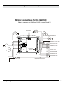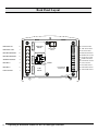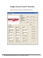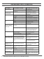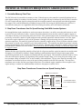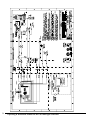
1
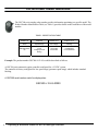
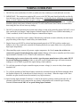
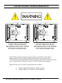
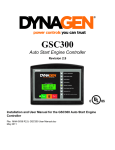
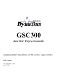
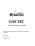
GSC300
Auto Start Engine Controller
Installation and User Manual for the GSC300 Auto Start Engine Controller
Full Version
File: GSC300_R2_6doc
September 2009
Operating & Installation Manual for the GSC300 Engine Controller
LIMITED WARRANTY POLICY: The Northern Lights GSC300 engine controller is warranted by the
original manufacturer, DynaGen Technologies Inc. DynaGen Technologies Inc. hereafter known as the Seller
warrants articles sold hereunder to be free from defects in material and workmanship. These express warranties
are the sole warranties of the Seller and any other warranties, expressed, implied in law, or implied in fact, are
hereby specifically excluded. The Seller’s sole obligation under its warranty shall be, at its option, to either issue
a credit, or repair or replace any article or part thereof, which is proved to be defective. Any adjustment of
credits will be based upon original billing prices. All warranties shall expire 5 years from date of shipment by
the seller, unless otherwise specified in other written communications from the Seller. Any replacement product
provided to the Buyer shall be subject to the original warranty period, which will expire 5 years from the date of
shipment of the original article. Notice of claimed breach of warranty must be given within the applicable
period. No allowances shall be made to the Buyer for any transportation, duties, brokerage fees, labor costs, or
parts adjustments or repairs, or any other work, unless said charges are authorized in writing, in advance, by the
Seller. The Seller shall, in no event, be liable for special or consequential damages or for loss of profit. The
warranty shall not extend to any articles or parts thereof which have been installed, used, or serviced, other than
in conformity with the Seller’s application specifications, manuals, bulletins, or instructions, or, if none, shall
have been subjected to improper installation, misuse, or neglect. The warranties shall not apply to any materials
or parts thereof, furnished by the Buyer, or acquired from others at the Buyer’s request and/or to the Buyer’s
specifications or designs. The foregoing limitations on the Seller’s liability in the event of breach of warranty
shall also be the absolute limit of the Seller’s liability in the event of the Seller’s negligence in manufacture,
installation, service, or otherwise, with regard to the articles covered hereby, and upon the expiration of the
stated warranty period, all such liabilities shall terminate.
RETURNS: If any article is claimed to be defective in material or workmanship, the Seller, upon notice
promptly given, will issue a written return material authorization (RMA) with shipping instructions for return to
the Seller. All returns must be accompanied by an RMA number or shipments will not be accepted by the Seller.
Articles which are returned as defective, but are found to meet the specifications agreed upon, will be subject to
a re-testing charge. At the discretion of the Seller, unused and undamaged Standard Products may, under certain
circumstances, be accepted back for credit or exchange. A restocking charge of 15% will apply. Unused custom
designed products will not be accepted back for credit or exchange.
For questions or comments regarding this product, contact:
Northern Lights
Phone (206) 789-3880
Fax (206) 782-5455
Email: [email protected]
Web: www.northern-lights.com
Operating & Installation Manual for the GSC300 Engine Controller
3
4
Operating & Installation Manual for the GSC300 Engine Controller
SPECIFICATIONS FOR THE GSC300
Operating Voltage:
7 to 30 VDC continuous
Zero volts operation for 100mS (assumes supply was 12 VDC
before initiating starting)
Operating Temperature:
-400C to +850C (LCD Display operates from to -160C to 700C)
Physical Dimensions:
4.5” (H) x 5.5” (W) x 1.25” (D)
Actual Unit Weight:
0.458 lbs
Enclosure:
High Impact Resistant, Injection Molded Plastic Enclosure
Front Panel Indications
-High intensity LED’s with regulated brightness
LCD Display:
-Ultra-bright, Backlight LCD display with optimum viewing angle of 0 - 250 from perpendicular
-Display Size (mm) 8 (W) x 32 (H) x 12.8 (D) x (2 line x 8 character display)
Adjustments
Warm-up:
0-200 Seconds (After Oil Bypass Feature)
Cool-Down:
0 - 812 Seconds
Crank Disconnect:
12 to 140 Hz
Overspeed:
40 - 200 Hz
Crank Rest:
4 - 32 Seconds
Delay on Start:
0 - 59 Seconds
Crank Tries:
1 to 10
Oil Bypass:
10 - 55 Seconds
Low Battery Indication:
7 - 35 VDC
Operating & Installation Manual for the GSC300 Engine Controller
5
Timer adjustments
Glow Plug/Preheat:
0 - 255 Seconds
Energize To Stop (ETS):
Energizes for 15 Seconds on failures, or energizes until 5 Seconds after
engine speed goes to zero upon removing power from Start/Stop terminal
or removing the unit from manual mode using the front panel buttons.
Inputs
Speed Sensing:
-Generator Output Speed Sensing
-Maximum Input Voltage:
300VAC RMS
-Minimum Input Voltage:
0.7VAC RMS Generator Output Sensing
-60Hz Rejection Filter Included
-Loss of Speed Signal Included
Sender/Failure Inputs:
Oil Pressure
Coolant Temperature
Fuel Level / Auxiliary Input
-Accepts standard industry low impedance (0-500 ohm) sender inputs
(VDO, Stewart-Warner, Datcon, Murphy, etc.)
-Custom senders can be accommodated for in PC programming
-Programmable for either switch or sender configuration
-Adjustable failure set-points
6
Operating & Installation Manual for the GSC300 Engine Controller
Protection
-Three on-board replaceable 40A fuses protect Fuel, Crank, and Timer Outputs
-Reverse polarity protected
-Short circuit & overload protection on annunciation outputs
-Inputs are electrostatic discharge protected
-Maximum power supply surge before damage: 1500V for 250us
Outputs:
-All outputs switched to +battery (sourcing)
-Fuel, Crank, and Timer Outputs:
40A each, using standard 40A automotive relays
-Annunciation Outputs:
300mA individually, 350mA combined
Connections
-Removable terminal block for annunciation outputs and low power connections
-0.25" spade terminals for high current and Main power inputs
Programming
-Windows based software interface utilizing the parallel port of your PC
-Option of programming through 3-button interface (limited parameter adjustment) on the front panel or
the PC Interface that has full parameter programming ability.
-Needs no power to program using the PC Interface – uses power from parallel port of PC
-Specifications May Change Without Notification
Operating & Installation Manual for the GSC300 Engine Controller
7
GSC300 Product Number Identification
The GSC300 series catalog order number provides information pertaining to a specific model. The
Product Number Identification Table (see Table 1) provides details on the breakdown of the model
number.
TABLE1: IDENTIFICATION TABLE
Position 1-6
Position 8
Position 10-11
Position 13-14
Series
Speed Range
DC Voltage
Labeling
GSC300=GSC3
00
L=Low
H=High (consult
factory)
12=12VDC
24=24VDC
LS=Standard
LX=Customized
Example: The product number GSC300-L-12-LS would be described as follows:
A GSC300 series automatic engine controller configured for a 12 VDC system.
The controller is factory configured for low speed range (generator speed range) which includes standard
labeling.
A GSC300 serial number would be displayed as:
GSC300-L-12-LS-00000
8
Operating & Installation Manual for the GSC300 Engine Controller
WIRING INSTALLATION GUIDELINES
Danger: Never work on the engine while its power is on. This controller does
not generate a warning signal prior to automatic engine start. Warning signs should
be placed on engine equipment indicating this important safety measure.
INSTRUCTIONS
Following these instructions will help avoid common installation problems during wiring and setup.
• Battery must be disconnected before any wiring connections are made.
• Wire length from the engine to the controller should not exceed 6 meters (20 feet).
Wiring size and type should be as specified below. Use stranded wire, since solid wire has a tendency to crack,
break and loosen over time.
TYPES AND SIZES
Terminal
1
2
3
4
5
6
7
8
9
10
11
12
13
14
15
16
17
18
19
20
21
22
Wire Size
(AWG)
12
12
12
12
12
12
12
12
18
18
18
18
18
18
18
18
18
18
18
18
18
18
Current max.
40A
40A
40A
40A
40A
40A
40A
40A
100mA
100mA
300mA
300mA
300mA
300mA
300mA
300mA
100mA
300mA
7mA
7mA
7mA
7mA
Function
Fuel Output Terminal
Auto(Battery +) Terminal Connection
Auto(Battery +) Terminal Connection
Crank Output Terminal
Ground Terminal Connection
Ground Terminal Connection
Preheat/ETS Terminal
Preheat/ETS Terminal
Speed Signal Connection
Speed Signal Connection
Overcrank (failure to start) Output
Overspeed Output
High Temp Output
Low Oil Output
Low Battery Output
Engine Run Output
Not in Auto Output
General Failure Output
Start/Stop Input
Oil Pressure Sender/Switch Input
Temperature Sender/Switch Input
Fuel Level/Auxiliary Sender/Switch
Input
Operating & Installation Manual for the GSC300 Engine Controller
9
WIRING GUIDELINES
1. DO NOT use wire smaller than 18 AWG as smaller wire has a tendency to crack and break over time.
2. IMPORTANT: The connections supplying DC power to the GSC300 panel should preferably run directly
from the battery posts with no splices or other connections. Avoid using chassis (aluminum or iron engine
parts), as return conductor for battery negative voltage. Copper wiring is recommended. Failure to follow
the above may result in erratic operation due to large voltage drops across wiring connections. A small fuse
should be placed at the battery terminal to provide 12 volts to the Remote Start Contacts to ensure that a
short along this line will not cause any damage.
3. DO NOT exceed the maximum rated current and voltage on each of the controller outputs. DO NOT exceed
40A each for the Fuel Output, Crank Output or Preheat Output. DO NOT exceed 300mA individually, or
350mA combined, for the General Fault Output or Annunciation Outputs.
4. 40Amp relays are rated for resistive ratings. When driving such loads as starter solenoids you must ensure
proper de-rating of the relays. Consult factory for further details.
5. Engine Sensor type MUST be selected and programmed properly to GSC300 (switch or sender type).
Failure to do so may result in the controller not shutting down on true engine failure (Low oil pressure or
high engine temperature).
6. When installing engine sensors (oil pressure, engine temperature, fuel level) ensure the switches are
connected to ground circuit through the engine sensor. Damage will occur to controller unit if the sensor
input terminals (Terminal #’s 20, 21 and 22) are connected to +Battery.
7. When using engine sensors that are the resistive type the proper manufacturer of the sender MUST
be selected during programming. Failure to select the correct manufacturer type will cause inaccurate
readings as well as failure to protect the engine during a fault condition.
8. To verify the operation of engine controller outputs, measure voltage (i.e. meter in volts) when outputs
should be ON.
9. To verify the operation of the Preheat Output, measure the resistance between the Preheat terminals when
the Preheat Output is ON, it should read a closed circuit (i.e. zero ohms). When the output is OFF there
should be an open circuit between the terminals (very high resistance).
10. Speed sensing input terminals (Terminal #’s 9 and 10) do not have polarity sensitivity therefore the AC
generator output leads can be connected in any polarity configuration to the controller speed sensing
terminals. Do not exceed 300VAC on speed sensing input terminals.
10
Operating & Installation Manual for the GSC300 Engine Controller
GSC300 12/24VDC SYSTEM OPERATION
!
PRE-HEAT
RELAY
9
10
7
6
5
JUMPER
3
2
FUEL
RELAY
12VDC RELAYS MUST
BE INSTALLED FOR 12VDC
SYSTEM OPERATION
PRE-HEAT
RELAY
9
10
7
6
5
4
24VDC
RELAYS
3
JUMPER
2
1
40 A
40 A
1
8
40 A
40 A
4
12VDC
RELAYS
22
21
20
19
18
17
16
15
14
13
12
11
40 A
40 A
8
!
FUEL
RELAY
22
21
20
19
18
17
16
15
14
13
12
11
24VDC RELAYS MUST
BE INSTALLED FOR 24VDC
SYSTEM OPERATION
The GSC300 controller is designed to operate in either 12 or 24VDC system voltages.
When operating in 12VDC systems the Fuel and Preheat/ETS relays need to be the
12VDC relay type. When operating in 24VDC systems these relays need to be the 24VDC relay
type. Contact the factory if relays are required. 24 VDC will require reprogramming.
Approved relays for 12 or 24VDC system operation are as follows:
•
•
Northern Lights P/N 22-42047 for 12VDC operation
Northern Lights P/N 22-40085 for 24VDC operation
Operating & Installation Manual for the GSC300 Engine Controller
11
TERMINAL DESCRIPTION
Term #
1
2,3
4
5,6
7,8
9 , 10
11
12
13
14
15
16
17
18
19
20
21
22
12
Description
Fuel Output provides 40A maximum. Fuel Output closes to +12/24VDC when start signal is received,
and opens when either an engine failure occurs or when Cool Down period has ended.
Auto Terminals. Main +Battery power connection to controller. These terminals are internally connected
together on GSC300 controller.
Crank Output provides 40A maximum. Crank Output closes to +12/24VDC during cranking, and opens
when the engine has started, or during Crank Rest.
Main Battery Ground connection for the controller module. A good ground connection, directly from
the battery, is required for proper operation. These terminals are internally connected together on
GSC300 controller.
Preheat/ETS Output provides a set of dry contacts between terminals #7 and #8. When this output is
energized terminals #7 and #8 are connected together. When output is OFF terminals #7 and #8 have no
connection.
Speed 1. Speed Signal Input for Crank Disconnect, Engine Run, and Overspeed sensing. 300VAC max
input voltage. Speed sensing input terminals (T#9, 10) do not have polarity sensitivity therefore the AC
generator output leads can be connected in any polarity configuration. Do not exceed 300VAC on speed
sensing input terminals.
Overcrank Annunciation Output closes to +12/24VDC on Overcrank Failure. 300mA max.
Overspeed Annunciation Output closes to +12/24VDC on Overspeed Failure. 300mA max.
High Temp Output closes to +12/24VDC upon High Temp Failure. 300mA max.
Low Oil Output closes to +12/24VDC upon Low Oil Failure. 300mA max.
Low Battery Output closes to +12/24VDC on Low Battery Condition. 300mA max.
Engine Run Output closes to +12/24VDC on Engine Run Condition. 300mA max.
Not In Auto Output closes to +12/24VDC when unit is not in auto. 300mA max.
General Failure Output closes to +12/24VDC on a General Failure. 300mA max.
Start Stop Input. Apply +12/24VDC to this terminal while unit is in Auto Mode to start engine. Remove
+12/24VDC to stop engine or enter Cool-Down mode.
Low Oil Pressure sensor input. This sensor can be the resistive type (Sender) or can be the switch type.
The proper type of sensor must be selected during GSC300 controller programming. The sender or
switch must be connected to ground for proper operation. If +Battery is connected to input terminal this
can result in damaged to GSC300 controller. When using a sender, the proper sender manufacturer must
be selected as each sender manufacturer’s characteristics are different; the sender failure set-point must
also be selected. When using a switch NO or NC much be selected from the programming menu. NO
refers to the state of the contacts during normal engine operation, therefore NO refers to normally open at
normal engine run and close to ground on low oil pressure failure.
High Engine Temperature sensor input. This sensor can be the resistive type (Sender) or can be the
switch type. The proper type of sensor must be selected during GSC300 controller programming. The
sender or switch must be connected to ground for proper operation. If +Battery is connected to input
terminal this can result in damaged to GSC300 controller. When using a sender, the proper sender
manufacturer must be selected as each sender manufacturer’s characteristics are different; the sender
failure set-point must also be selected. When using a switch the switch must be the NO type on normal
engine run and close to ground on failure.
Fuel Level sensor or Auxiliary failure input. This sensor can be the resistive type (Sender) or can be the
switch type. The proper type of sensor must be selected during GSC300 controller programming. The
sender or switch must be connected to ground for proper operation. If +Battery is connected to input
terminal this can result in damaged to GSC300 controller. When using a sender, the proper sender
manufacturer must be selected as each sender manufacturer’s characteristics are different. When using a
switch the switch must be the NO type on normal engine run and close to ground on failure.
Operating & Installation Manual for the GSC300 Engine Controller
Wiring Connection Diagram
Wiring Connections for the GSC300
(Refer to schematics No. B-9696 and B-9691 on pages 24 and 25.)
SHUTDOWN SWITCHES
GENERATOR OUTPUT
UP TO 300VAC
TEMPERATURE SENDER/SWITCH
Glow
Plug &
ETS
OIL PRESSURE SENDER/SWITCH
40 A
8
PRE-HEAT
RELAY
9
10
7
6
5
4
40 A
CRANK
3
JUMPER
2
1
40 A
FUEL
FUEL
RELAY
PIN 1
PROGRAMMING
CONNECTOR
22
21
20
19
18
17
16
15
14
13
12
11
MODE SWITCH
GENERAL FAILURE LAMP
NOT IN AUTO LAMP
ENGINE RUN LAMP
LOW BATT LAMP
LOW OIL LAMP
HIGH TEMP LAMP
OVERSPEED LAMP
OVERCRANK LAMP
(-)
(+)
BATTERY
½ AMP FUSE
REMOTE START CONTACTS
Operating & Installation Manual for the GSC300 Engine Controller
13
Back Panel Layout
PRE-HEAT COM
7
BATTERY GROUND
6
BATTERY GROUND
5
STARTER OUTPUT
4
BATTERY +
3
BATTERY +
2
1
9
SPEED SIGNAL
INPUTS
FUEL
RELAY
PROGRAMMING
CONNECTOR
ON
MODE SWITCH
14
22
21
20
19
18
17
16
15
14
13
12
11
10
JUMPER
40 A
FUEL OUTPUT
PRE-HEAT
RELAY
40 A
8
40 A
PRE-HEAT NO
Operating & Installation Manual for the GSC300 Engine Controller
OFF
AUX SWITCH INPUT
TEMP. SWITCH INPUT
OIL SWITCH INPUT
REMOTE START INPUT
GENERAL FAIL OUTPUT
NOT IN AUTO OUTPUT
ENGINE RUN OUTPUT
LOW BATTERY OUTPUT
LOW OIL OUTPUT
HIGH TEMP. OUTPUT
OVER-SPEED OUTPUT
OVER-CRANK OUTPUT
CONTROLLER OVERVIEW
1.
2.
3.
4.
5.
6.
7.
8.
General Failure Conditions
Not In Auto
Low Battery Voltage Alarm
Oil Pressure Input
Coolant Temperature Input
Fuel Level/Auxiliary Input
Speed Signal Sensing
Adjustable Input Programming
1: GENERAL FAILURE CONDITIONS: The following conditions can cause the GSC300 controller
to shutdown the engine-generator system unexpectedly:
Auxiliary Failure (“XTR_FAIL”)
Low Oil Pressure
High Coolant Temperature
Overcrank
Overspeed
Loss of Speed (“SPDLOSS”)
Extra failure is indicated by a flashing RED Low oil pressure LED
Low Oil pressure is indicated by a steady on RED Low oil pressure LED
High coolant temperature is indicated by a steady on RED High water temp LED
Overcrank failure is indicated by a steady on RED Overcrank LED
Overspeed failure is indicated by a steady on RED Overspeed LED
Loss of speed signal is indicated by a flashing RED Overspeed LED
The General Failure output annunciation is triggered during any of the above failure conditions and is rated
300mA Max.
2: NOT IN AUTO: When the controller is in the OFF Mode, the NOT IN AUTO LED will illuminate and
the NOT IN AUTO Output will be triggered. During this OFF mode Automatic engine starting is disabled. The
LCD display will read “OFF”, and the backlight on the LCD display will be off.
NOTE: + Battery must be permanently connected to the main power terminal for the NOT IN AUTO
feature.
3: LOW BATTERY VOLTAGE ALARM: When the battery voltage drops below the user defined
set point which can be programmed between 7 and 35VDC, the engine controller displays a Low Battery
Condition. The Low battery warning Led will be illuminated at any time during OFF, AUTO and Manual run
modes. The LCD display will indicate the message: “LOW_BATT”. The LOW battery warning will be
disabled during failure conditions.
4: LOW OIL INPUT: The Low Oil Input can be wired to a resistive sender or from a NO or NC type
switch. NO / NC refers to the state of the contacts during normal engine operation (engine oil pressure ok).
When utilizing a resistive sender the display units are fixed in PSI by the PC programming interface, and a
failure set-point must be selected from the programming menu.
Note: The oil input failure is disabled during the Oil Bypass time.
Operating & Installation Manual for the GSC300 Engine Controller
15
5: HIGH TEMPERATURE INPUT: The high temperature input can be wired to a resistive sender or
from a NO type switch. For proper operation while using a switch, the switch must be the NO type which
closes to ground upon failure. When utilizing a resistive sender the display units are fixed in Fahrenheit by the
PC programming interface, and a failure set-point must be selected from the programming menu.
Note: The engine temperature failure is disabled during the Oil Bypass time.
6: FUEL LEVEL/AUXILIARY INPUT: The Fuel level/Aux input can be wired to a resistive sender
or from a NO type switch. For proper operation while using a switch, the switch must be the NO type which
closes to ground upon failure. If this input is used as a sender, no failure will be indicated. The sender option is
solely for Fuel Level/Auxiliary Level Display on the LCD. Northern Lights, Inc. uses this input to connect the
engine shutdown switches as a backup to the primary shutdown inputs.
7: SPEED SIGNAL SENSITIVITY: The controller will accept to a maximum of 300VAC, 60Hz from
direct generator output for speed sensing. The following values are minimal recommended voltages for speed
signal sensing:
20Hz - .075V (75mV)
60HZ - .6V (600mV)
8: HOUR METER: The controller displays a log of total accumulated generator running hours. Generator
Run times will be displayed on the controllers display screen. The display represents both hours and minutes in
the form 123456:7. The last digit on the hour meter will represent the time in 1/10 of an hour. Please note that
although the hour meter displays time in hours and minutes, it will record up to the nearest second. If the
generator was operated for a 3 minute period and then stopped the running time is stored in permanent memory
and then adding to the next running period. The same would be true if the controller were to enter a failure
mode as the controller would permanently store the remaining time for the next running cycle.
16
Operating & Installation Manual for the GSC300 Engine Controller
LED LAYOUT
Front View of GSC300
Operating & Installation Manual for the GSC300 Engine Controller
17
LED INDICATIONS
FRONT PANEL LED INDICATIONS
LED Appearance
Not in Auto LED is ON.
No LED’s ON
Steady Low Oil LED
Flashing Low Oil LED
Steady High Temperature LED
Steady Overcrank LED
Steady Overspeed LED
Flashing Overspeed LED
Steady Engine Running LED
Flashing Engine Running LED
18
Condition/Failure
Unit is in OFF state, and automatic starting
is disabled
“OFF”, no +12/24VDC to main power
terminal.
Low Oil Pressure Failure
Auxiliary Input Failure
Over Temperature Failure
Engine-generator failed to start after the
specified number of cranking attempts.
Speed Signal present above Overspeed
setting
The speed signal was Zero while running.
The engine has stalled (overload or lack of
fuel), or the speed signal has been lost.
Engine Controller is in running mode of
operation.
Crank Rest period. Cranking will resume
soon.
Operating & Installation Manual for the GSC300 Engine Controller
Programming The GSC300 Settings
Using the Front Panel Interface:
The following table shows the LED’s that correspond to the various settings of the various parameters. To
enter the controller into Program Mode, you need to turn the small switch at the bottom edge of the controller to
the program position (See Diagram on Pg 12). This Mode Switch can be set using a ballpoint pen or small tool
to allow the controller to be put into Program Mode. The first three LED’s (3, 2 & 1) correspond to which
Parameter is being adjusted, and the next three (6, 5 & 4) LED’s show the Value for that particular
Parameter.
LED 1 = Low oil pressure
LED 2 = High water temp
LED 3 = Overcrank
LED 4 = Overspeed
LED 5 = Engine Running
LED 6 = Low engine battery
LED7 = Preheat/ETS
LED8 = NOT IN AUTO (starting disabled)
The picture on the next page shows the LED numbering and the location of the Mode Switch.
The highlighted circle in the table refers to the LED being illuminated.
▼ LED's 6, 5 & 4 ▼
Parameter
LED's 3, 2 & 1
▼
○○○
○○●
○●○
○●●
●○○
●○●
●●○
●●●
Crank Tries
○○○
1
2
3
4
5
6
7
8
Crank Time
○○●
5
10
15
20
25
30
35
40
Rest Time
○●○
0
5
10
15
20
25
30
35
Preheat Time
○●●
0
5
10
15
20
25
30
35
Cool-Down
●○○
0
32
64
96
128
160
192
224
Preheat/ETS/
Warm-Up
●○●
Preheat
ETS
Warm-Up
N/A
N/A
N/A
N/A
N/A
Warm-Up
●●○
0
28
56
84
112
140
168
196
To scroll through the parameters simply press the Auto button on the front panel of the GSC300. To scroll
through the range of values for that parameter simply press the Manual Start button. To program the
value into the controller’s memory, press the OFF button. In this manner the settings of the controller can
be adjusted by simply using the three buttons on the front panel of the controller. Be sure to press the OFF
button when you have selected the parameter value wanted.
Operating & Installation Manual for the GSC300 Engine Controller
19
Numbering of LED’s and Location of Mode Switch
LED #1
LED #2
LED #3
LED #4
LED #5
LED #6
Mode Switch
Programming Using the PC Interface
The GSC300 can also be programmed using the PC interface. Detailed instructions on the
PC interface are included with the GSC300 Configurator software. A sample interface screen is
illustrated on the following page.
20
Operating & Installation Manual for the GSC300 Engine Controller
Sample Screen From PC Interface
NOTE: Factory default settings are outlined in the photo below.
Operating & Installation Manual for the GSC300 Engine Controller
21
TROUBLESHOOTING GUIDELINES
TROUBLE
Unit does not operate when
powered to test mode
Engine starts and
immediately goes into
Overspeed shutdown
Engine does not crank
Engine cranks but does not
start
Engine starts but shuts
down after “Oil BypassTM
period” due to low oil/high
temp/Aux input
Bad ground connection from engine to
controller unit.
Improper Overspeed setting
Battery is low or terminals are dirty
Crank circuitry wiring improperly
connected
Bad ground connection from engine to
controller
Crank relay damaged. Or on board fuse is
blown
Out of fuel
Ignition control wiring not installed
properly
Fuel relay and or fuse damaged
Oil/Temp/Auxiliary input wiring improperly
connected.
SUGGESTED ACTION
Confirm correct wiring for ground and +bat,
and re-attempt testing.
Run wire directly from battery - to the
ground terminal #11on controller unit.
Verify the Overspeed setting with PC
configuration software. Confirm that
engine’s governor is properly calibrated for
its intended use.
Clean terminals and re-charge battery
Refer to engine control wiring section and
check crank connections
Run wire directly from battery - to the
ground terminal #5 & 6, on controller unit.
Check wiring, in line fuse and slave relay.
Replace fuse, relay and re-test controller.
Check fuel level, add fuel if necessary
Refer to engine control wiring section and
check ignition connections
Check fuel relay and fuse, replace if
damaged or blown.
Check wiring for proper connections.
Incorrect programming of sensor inputs.
Check programming of oil pressure, engine
temperature and aux input. Ensure that the
sensor type is properly programmed to
controller unit (Sender / Switch type)
Flashing Overspeed LED
Speed signal improperly connected,
missing, or damaged.
Crank output damaged, not working, or
fuse blown on starter output
Starter or starter solenoid damaged
Check speed signal wiring; replace
damaged speed signal source.
Check wiring and replace relay of fuse
where necessary.
Replace/repair damaged starter or starter
solenoid.
Steady Oil LED immediately
on start-up, without engine
actually cranking or starting.
False speed signal being detected by
controller. This problem can sometimes
occur in installations where there is AC
power from inverters near generator
output lines connected to the speed signal
cable.
Install a small step down transformer
between the speed sensing wires and the
generator output.
Display Parameter for
Temperature, Oil or Fuel
displayed as >>> or <<<
Parameter is >>> ABOVE or <<< BELOW
specified manufacturer sender range.
If further accuracy is required it may be
necessary to install sender with proper
range specifications.
Warm-Up Feature appears
longer then time setting.
Warm-Up Feature time setting does not
begin until the Oil Bypass Time has
expired.
Re-adjust Oil Bypass and/or Warm-Up
timing.
Engine cranks immediately
when battery is started up.
Battery Discharged.
(Low battery voltage alarm.)
22
POSSIBLE CAUSE
Power leads to unit are reversed
GSC300 was in autostart when battery was
disconnected.
GSC300 was in autostart and battery was
dead when charger was hooked up.
GSC300 has a 45 ma load in standby mode.
If the neutral from the generator output is
not grounded, attach it to ground
Make sure GSC300 is shut off prior to
battery being disconnected.
Press off when hooking up charger.
Use a battery disconnect switch, install
a larger battery, or install a battery charger/
maintainer.
Operating & Installation Manual for the GSC300 Engine Controller
TECHNICAL NOTES ON FREQUENTLY ASKED QUESTIONS
1. Controller Memory Clear Time
The GSC300 needs 10 seconds for its memory to clear. When the power to the controller is turned off and then back on
again without waiting 10 seconds to clear the memory, a loss of speed will may be indicated by the GSC300 (if controller
is in AUTO mode and start signal is activated) because the controller remains in run mode and senses that the generator
has stopped. This would be indicated by a Flashing Overspeed LED. By leaving the GSC300 main power OFF for 10
seconds before main power is re-applied this allows the clearing the memory and it will function as intended.
2. Step Down Transformer Use On Speed Sensing Cable With Inverter Systems
In some applications engine controllers are used on generators where there is no utility connection and inverters are used
to provide AC power instead of a utility. Inverters can produce harmonics that can cause small AC signals to appear on
wires that are near any power lines being fed by the inverter. If the generator output wires are located close to a line being
powered by an inverter, a small AC signal can appear on the generator output lines when the inverter is on. This signal
can cause the engine controller to react as if the generator is running if the speed sensing wires are connected to the
generator output lines. This small AC signal can cause the controller to appear to have a Low Oil Failure when the remote
start contacts are closed or the controller is put in the manual/test mode. The controller may think the generator is already
running and immediately check to make sure there is oil pressure. Since the engine really hasn’t started yet, there is no oil
pressure and the controller sees a low oil fault. This is seen as the Oil LED turning on steady even before the engine starts
to engage the starter.
Without this false speed signal the controller will not look for oil pressure until the engine has started to run and the crank
disengages if oil verification is disabled. Simply installing a small transformer between the generator output and the
speed sensing terminals on the controller can eliminate this false speed signal. This transformer should be rated for 120 or
240 volts on the input or primary coil (depending on the generator output voltage you are using for speed sensing), and
have an output voltage of around 12VAC on the secondary of the transformer. The two wires from the secondary of the
transformer are connected to the two wires of the speed sensing terminals on the GSC300 controller. The step-down
transformer acts to reduce the false speed signal on the line to a level that the engine controller will not recognize as the
engine running. A common size transformer that would serve this purpose would be 24VA.
Step Down Transformer Connections on Speed Sensing Cable
Step Down Transformer
#9
12VAC
Secondary
Winding
#10
120VAC
Primary
Winding
To Generator Output
Line to Neutral 120VAC
Twisted pair of wires connected to
speed sensing terminals on GSC300
Operating & Installation Manual for the GSC300 Engine Controller
23
24
Operating & Installation Manual for the GSC300 Engine Controller
Operating & Installation Manual for the GSC300 Engine Controller
25
26
Operating & Installation Manual for the GSC300 Engine Controller
Operating & Installation Manual for the GSC300 Engine Controller
27
Operating & Installation Manual for the GSC300 Engine Controller
Operating & Installation Manual for the GSC300 Engine Controller
4420 14th Ave. NW
Seattle, WA 98107-4616, USA
Tel: (206) 789-3880 • Toll Free 1-800-762-0165
Fax: (206) 782-5455 • www.northern-lights.com
Northern Lights and Lugger are products of Northern Lights, Inc.
c 2009 All rights reserved. Litho in USA OGSC300