1
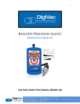
INSTRUCTION MANUAL
DIGIVAC Model 801 Series
Digital Vacuum Gauge
801W
801W Ranges
.001 to 760 Torr
1 to 9999 microns
.001 to 999 millibar
YOU MUST READ THIS MANUAL BEFORE USE
The DigiVac Company
105B Church Street
Matawan, NJ 07747
Ph: 732.765.0900
Fax: 732.765.1800
www.DigiVac.com
CONTENTS
1.0
Description and Principle of Operation
2.0
Construction
3.0
Unpacking and Inspection
4.0
Installation
5.0
Operation
6.0
Servicing, Maintenance and Calibration
6.1 Factory Repair and Calibration
6.2 Field Calibration
7.0
Notes on Calibration
8.0
Understanding Torr
9.0
Accessories and Modifications
10.0
Attachments, Illustrations and Specifications
11.0
Terms and Conditions
2
1.0
DESCRIPTION AND PRINCIPLE OF OPERATION.
The DIGIVAC 801 series gauge is a compact digital vacuum sensing instrument. It uses a
thermocouple gauge tube to sense vacuum and display the reading in either milliTorr or
mbar. The DigiVac Model 801 can be panel mounted using the same cutout and hole
mounting pattern of a traditional Varian 801 pointer meter gauge.
Consult the DigiVac website www.DigiVac.com for information about other DigiVac
vacuum controllers and gauges.
The DigiVac Model 801 operates by measuring the temperature rise of an electrically
heated thermocouple exposed to a vacuum. As vacuum increases, or more correctly, as
absolute pressure decreases, fewer and fewer molecules of gas are available to cool the
thermocouple. With less molecules the air temperature rises and the thermocouple
gauge thus senses the vacuum. A precision reference inside the DigiVac in conjunction
with an integrated circuit amplifier controls the electrical excitation of the sensor
filament. The voltage response of the thermocouple is piped through a CPU and is
translated to the current vacuum reading.
2.0
CONSTRUCTION
The 801 consists of the indicating and controlling instrument, the gauge tube, the
gauge tube cable, AC power supply, and if so equipped also has interfaces for the 2
control connections, analog out, and RS232.
The gauge tube houses the various thermocouple sensing, heating and compensating
elements and terminates in an octal connector. On this model, the connector wiring
terminates at the instrument with a 6 position RJ24. Regulating circuitry in the DigiVac
provides proper current for gauge tube excitation, and thus compensates for resistance
in the probe leads.
3.0
UNPACKING AND INSPECTION
After the DIGIVAC is received, it should be carefully unpacked and inspected for damage
during shipment and for completeness. In the event of a loss during shipment, a claim
should immediately be made to the common carrier or the postal service, as applicable.
The DigiVac warranty pertains only to the instrument, and does not cover losses in
shipping.
Each 801 should come with:
Display controller
AC Power supply with AC wiring adapter
Gauge Tube Cable
Varian 531 gauge tube
Mounting Hardware
If ordered with additional options, it will also come with:
3
AC power supply with international adapters (instead of above)
5V5T analog recorder terminal connector
RS232 DB9 connector
Terminal connector for U and L relays
4.0
INSTALLATION
The instrument should be located in a clean, dry environment for best results. The unit
can be panel mounted with the hardware provided:
•
•
•
•
Remove the front panel of the gauge, leaving the aluminum spacers on the gauge printed
circuit board.
Make a 2.66" circular mounting hole in the panel at the desired location
Make 3 or 4 holes, 5/32" diameter (clearance holes for #4 screws) on a 1.58 radius from the
center of the mounting hole. (The front panel that comes with the gauge can be used as a
template.)
Reassemble the gauge, with the plastic panel outside, and the gauge behind.
The gauge tube cable should be identified by wire tags or markings specific to your
environment.
Thermocouple gauge tubes must be installed in a thread-down orientation in a clean,
dry vacuum system. While threading the gauge tube in to the manifold, the gauge tube
cable should be disconnected to avoid damage. In this way, twisting of the cable and the
octal socket on the tube is avoided. Care should be exercised to install the tubes in a
dry part of the system. Since the instrument works on the principle of temperature rise,
the probes will not work if they become filled with a liquid such as vacuum or diffusion
pump oil. The gauge tube should be protected against oil and other contaminants by
installing it in such a way to protect it. A good practice is to mount the gauge tube in
the most vertically distant place from oil and other contaminants as applicable. The
gauge tube should be mounted in the most stable pressure region of the vessel to be
measured. For example, it would be better to install the gauge tube on a tank rather
than on the pipe that is directly connected to a vacuum pump. In the event of
contamination, see section 6.0 for gauge tube cleaning instructions.
If the gauge is used in a Neon sign processing facility, the following is recommended to
protect the gauge from bombarding damage:
The gauge tube should be isolated from the system with a stopcock. The stopcock
should be closed when bombarding.
There should be at least 2 feet of tubing between the electrode and the Instrument.
For best results, the tubing should be metal.
In extreme cases, the gauge can be absolutely protected by installing a normally open
solenoid valve between the gauge tube and the system. The solenoid valve coil should
be in parallel with the bombarding transformer. In this way, the solenoid will be
closed and the gauge tube will be positively protected whenever bombarding is done.
If a gauge is damaged by bombarding, it can generally be brought back to operating
condition by replacing the Op amp which controls the gauge tube current. Consult
DigiVac.
4
The set point connections are in the back of
the unit. There is one row of pins with a
terminal strip connector for the 2 set point
connections. The set point connections are
in the order:
1. Common – The common line of a
switch
2. N.C. – Normally closed. This means that above the set point value there is a current
path between the common and the N.C. terminal. Put another way the switch is “ON”
between these 2 terminals. At the set point value and below (higher vacuum, lower
pressure) the connection is open. Put another way, the switch is “OFF” between the
common and the N.C. connection at higher vacuum (a lower pressure reading).
3. N.O. – Normally open. This means that above the set point value there is no current
path between the common and N.O. connection. Put another way the switch is “OFF”
between these 2 terminals. When the vacuum indication goes below the set point
value (higher vacuum, lower pressure) the current path closes. Put another way the
switch is “ON” between the common and N.O. connections at absolute pressure
readings below the set point value.
Take care to insure that the wire connections are made fast, and the voltage and current
does not exceed 250V or 7A. If you need to control a device that draws more power,
consider another relay in between the DigiVac output and the device to be controlled
The Analog output is located in the center of the back panel, and should be connected
to a high impedance input. The output impedance is 1KΩ.
The RS232 connection can be made to a PLC or computer via a male DB9 cable
connection to the female DB9 connection on the DigiVac. The DigiVac acts as a DCE, so
a straight serial connection is appropriate.
Please use the supplied 5V AC adapter with your Instrument. This adapter provides clean
short protected power to protect and insure proper functioning of the internal circuitry.
5.0
OPERATION
After installation, the Instrument is ready for immediate operation. The unit will
normally provide accurate readings immediately however, occasionally a gauge tube will
have absorbed material during storage, and may require as much as 24 hours of
operation before accurate readings are attained. It is recommended that the DIGIVAC be
energized continuously during vacuum system operation. In this way, the hot filament
will not allow contaminants to condense.
In cases where the system has contaminants, as is often the case with metalizing and
coating equipment, it is often effective to isolate the gauge tube with a solenoid or
manual valve during periods when contamination is most active.
5
The DigiVac 801 has 2 set points that can
be used to actuate external equipment.
These 2 set points can be adjusted from
the front of the gauge in your currently
selected units.
1. To change SP1:
a. Press the “U” button- set point 1 will
be displayed
b. Turn the “SP1” or the left most
potentiometer when looking at the
front face of the 801 to adjust set
point 1 to the desired level
2. To change SP2:
a. Press the “L” button- set point 2 will be displayed
b. Turn the “SP2” or the right most potentiometer when looking at the front face of
the 801 to adjust set point 2 to the desired level
3. If you don’t want the set points to actuate at all, set the set point for “000”.
The Instrument has additional outputs which can be used:
RS232 – The instrument puts out a standard RS232 serial stream with settings 9600,
8, N, and 1. The unit transmits but does not receive, and displays the current vacuum
indication in the current units.
Analog out – This output reads from 0 to 5 Volts from a pressure of 1 micron all the
way up to 5 Torr. There is a graduation of 1 milliVolt per milliTorr. Therefore, 10
milliVolts = 10 milliTorr, and 4 Volts = 4 Torr.
6.0
SERVICING AND MAINTENANCE
GAUGE TUBE SERVICING
In many cases, a gauge tube may become fouled with oil or other foreign matter. It is
often possible to restore the functionality of contaminated probes with cleaning. If the
contaminant is known, the tube should be filled with a fluid that is known to be a
solvent to that contaminant. As an example, ether is often effective in removing
residues of some oils. Commercial carburetor cleaners are very powerful solvents and
are highly effective against some contaminants.
After cleaning with solvents, the gauge tube should be completely dried or flushed with
a volatile solvent to assure that it is dry prior to re-installing it. If this is not done,
contamination of the system may result.
MAINTENANCE
Your vacuum instrument should give you many years of trouble free service. There are
no regularly scheduled maintenance intervals. If consistent accuracy is required, it is
recommended that the gauge, tube, cable and power supply be returned for a yearly
calibration check.
6.1
FACTORY REPAIR AND CALIBRATION
6
The vacuum gauge assembly is designed to provide years of trouble-free service, and
the liberal internal use of plug-in components make it easily repairable. No field
servicing of the unit is recommended, other than replacement of the gauge tube, but
factory servicing and calibration are available at a nominal cost and fast turn-around
times.
6.2
FIELD CALIBRATION
Each DigiVac vacuum gauge controller is calibrated to the particular vacuum gauge
sensor that is shipped with the unit. While changing the gauge tube is possible, it will
result in a slightly different reading as all gauge tubes are not created equal. Although
it is preferable that all calibration be performed at DigiVac, field calibration can be
accomplished.
Before re-calibrating the instrument, it should be ascertained that the instrument is in
fact incorrect. In many cases, the problem will be with a tube that is fouled, or a system
that is operating improperly. It is recommended that a spare tube be kept on hand and
stored in a clean, dry place. Then, in cases of suspect readings, the tube should be
changed before proceeding further.
If adjustments are to be made, proceed as follows:
A) Remove the Instrument from the panel.
B) The “Zero” potentiometer is at the top center just below the top mounting hole as
you look at the LED Display, the “ATM” or span adjust is to the left on the back of the
board on the same side as the sensor RJ connector.
C) Operate the vacuum system at the lowest attainable pressure, and allow the system
and the gauge tube to stabilize for several minutes. Factory zero setting is done at a
pressure of .1 milliTorr (.1 micron) or less.
D) Adjust the zero setting potentiometer so the unit reads zero. Make sure not to under
span. Allow the measurement standard to rise to 1 milliTorr and make sure the
gauge reading also reads 1 milliTorr.
E) Check the operation of the gauge at other pressures. Normally, slight adjustments of
the zero will not be interactive with the readings of the instrument at higher
pressures.
F) The ATM adjustment is normally not necessary. If necessary, adjust the span with
the ATM potentiometer.
a. Set the vacuum level to Atmosphere (approximately 760 Torr) and slowly turn the
potentiometer on the right until the DigiVac gauge reads 760 Torr, being careful
not to over span.
b. If you adjust the span, recheck the zero, then the span, and the zero one last
time.
7.0
NOTES ON CALIBRATION
The instrument is calibrated in nitrogen, which has thermal properties virtually identical
to air. Other gasses will affect the readings by an amount proportional to the thermal
conductivity of the gases. In most cases, the gases present in a vacuum system will be
air, nitrogen, or oxygen, and no appreciable errors will occur.
7
Certain other gases, however, have thermal conductivity significantly greater than air
and will cause the instrument to read higher than the actual amount of pressure.
Examples of such gasses are water vapor, fluorocarbon refrigerants, and acetone.
Conversely, other gasses have thermal conductivity significantly lower than air and will
cause the instrument to read lower than actual pressure. Examples of such gasses
include helium, oxygen and to a lesser extent, CO2.
When interpreting readings using gasses other than air, it should be borne in mind that
the DIGIVAC reads Torr, which is a measure of absolute pressure - that is the opposite
of vacuum. Thus, a lower numerical reading actually is a higher level of vacuum. For
more information, refer to section 8.0.
When in doubt, consult DigiVac.
8.0
UNDERSTANDING TORR
The DIGIVAC and many similar instruments are calibrated in microns or "milliTorr." It is
appropriate to discuss what microns are and to relate microns to other measures of
pressure and vacuum. Microns are not really a measure of vacuum at all, but rather of
absolute pressure. It will be recalled that the pressure of the atmosphere is 14.696 or
approximately 14.7 pounds per square inch at sea level. This pressure is due to the
weight of all of the air in the earth's atmosphere above any particular square inch. This
14.696 psi is equivalent to the pressure produced by a mercury column of
approximately 29.92 inches high or .76 meters (about 3/4 of a yard) or 760 millimeters
of mercury. Atmospheric pressure varies greatly with altitude. It decreases
approximately 1 inch of mercury per thousand feet of altitude. It also varies widely with
local weather conditions. (Variations of one half inch in a single day are common.) The
word vacuum means pressure lower than atmospheric or "suction," but, in describing
negative pressure, the atmosphere is only a satisfactory reference if we are dealing with
values of vacuum down to about 27 inches of mercury. Below that, it is much more
useful to talk in terms of absolute pressure, starting from absolute zero. The 801 and all
similar instruments do just this.
One TORR, a commonly used unit, is an absolute pressure of one millimeter of mercury.
A milliTorr is equal to one thousandth of a TORR. A MICRON is the same as a milliTorr.
9.0
ACCESSORIES AND MODIFICATIONS
Please consult the product guide and website for the latest available accessories. We
also offer analog output, RS232 and 2 set point controls as production options to the
801W.
SPECIAL REQUIREMENTS
It is the policy of the DigiVac Company to customize instruments for specialized
requirements whenever it is economically feasible to do so. We encourage inquiries
about your special needs.
8
10.0
10.0
SPECIFICATIONS
Input Voltage
Voltage
0.5A at 5VDC
Maximum Relay Voltage and Current
250VAC at 7 Amps
Recommended wire gauge for analog and
set point wiring
1414-28 AWG
Maintenance Interval
1-10 years depending on use
Overall Dimensions,
Dimensions, front panel
4.0 in wide, 3.5 in high, 1.4 in deep
Panel Cutout Dimensions
2.66 inch diameter cutout
Ambient Operating range
0°C to 70°
70°C
Measurement Media
Clean Dry Air or Nitrogen
There may be impairment to the protection of the equipment if it is used in
a manner that is not specified.
Instrument Accuracy:
.001 to .010 Torr
+/+/- .001 Torr
.010 to 2.00 Torr
+/+/- 10% of reading
2.0 to 160 Torr
+/+/- 50% of reading
160 to 760 Torr
+/+/- 25% of reading
For repair or recalibration, return gauges to:
The DigiVac Company
105B Church Street
Matawan, NJ 07747
Ph:
Fax:
732.765.0900
732.765.1800
E-mail: Direct from our website www.DigiVac
www.DigiVac.com
DigiVac.com
The DigiVac Company manufactures a complete line of vacuum gauges and
process computers. Contact us or your distributor if you wish for further
information.
See www.DigiVac.com for our latest offerings
9
11.0 TERMS AND CONDITIONS
.
TERMS OF USE, LIMITED WARRANTY & LIABILITY WAIVER
THE DIGIVAC COMPANY (“DigiVac”) offers all of its products with the following terms and conditions
and notices as follows. By accepting and/or using a DigiVac product, you hereby acknowledge and
agree to the following terms and conditions, and acceptance of these terms and conditions are a condition
precedent to any purchase/sale agreement between you and DigiVac.
EXCLUSIVE OBLIGATION: The DigiVac product you are purchasing has been designed for a specific
use within a set of suitable operating conditions, as set forth in its User Manual, or as indicated otherwise
by DigiVac. Any use of the DigiVac Product for any purpose or under any conditions, other than those
specified, shall render any limited warranty void, and shall expressly invalidate any liability of DigiVac
for damages as a result of such misuse. USER LIMITATION: You may not modify, copy, distribute,
transmit, display, perform, reproduce, publish, license, create derivative works from, transfer, or sell, any
information, software, products or services obtained from or created by DigiVac to any third party,
without the express written consent of DigiVac to do otherwise. Any violation of this provision shall give
rise to an indemnification of DigiVac by you, for any third party claims arising out of such violation.
THIRTY (30) DAY LIMITED WARRANTY: All DigiVac products are warranted against any
manufactured defect for a period of thirty (30) days from date of purchase, unless such product is a
custom-work for you and not a standard DigiVac product. Any product qualifying as a custom-work
shall not be warranted against any defects for any purpose, and your acceptance of such custom-work
shall relieve DigiVac of any liability for any purpose. WITH THE EXCEPTION OF THE LIMITED
WARRRANTY ABOVE, YOU AGREE ANY DIGIVAC PRODUCT IS PROVIDED AS IS, EXCLUSIVE OF
ANY WARRANTY, INCLUDING, WITHOUT LIMITATION, ANY IMPLIED WARRANTY OF
MERCHANTABILITY, FITNESS FOR A PARTICULAR PURPOSE, NON-INFRINGEMENT, OR ANY
OTHER WARRANTY, EXPRESSED OR IMPLIED. LIMITATION OF LIABILITY: You agree and
acknowledge, DigiVac shall have no liability to you whatsoever for any direct, indirect, punitive,
incidental, special consequential damages arising out of or connected with the use or misuse of its
products. In particular, given the nature of DigiVac products, you agree and acknowledge, under no
circumstances whatsoever shall DigiVac be liable to you for any consequential damages for damage to
any non-DigiVac product or service, arising from the failure, use or misuse of a DigiVac product,
including, but not limited to, any vacuum system, engine, vehicle, factory, or the like. In the event, a
court of law with proper jurisdiction finds DigiVac liable to you for any purpose, you agree and
acknowledge DigiVac’s maximum liability shall not exceed the purchase price of one unit of product
giving rise to such liability, or $250.00, whichever is greater. ENTIRE OBLIGATION: These terms and
conditions express the entire obligation of DigiVac with respect to its products. If any part of these terms
and conditions are deemed void, invalid, unenforceable or illegal, including, but not limited to, the
warranty disclaimers, liability disclaimers and liability limitations set forth above, then the unenforceable
clause or sentence may be disregarded with the remainder of these terms and conditions valid and
enforced. In the event the unenforceable clause or sentence leaves a void in these terms and conditions, a
provision closely matching the intent of the unenforceable provision should be deemed inherent within
these terms and conditions, slightly modified to render such provision valid and enforceable.
GENERAL: These terms and conditions are governed by the laws of the State of New Jersey, USA. You
hereby consent to the exclusive jurisdiction and venue of the Courts of New Jersey, in all disputes arising
out of or relating to the use of this product. Use of this product is unauthorized in any jurisdiction that
does not give effect to all provisions of these terms and conditions. MODIFICATION OF TERMS AND
CONDITIONS: DigiVac reserves the right to change the terms, conditions, and notices under which their
products are offered.
10