1
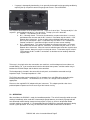
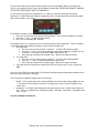
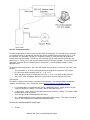
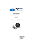
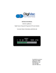
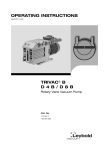
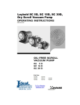
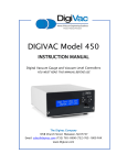
INSTRUCTION MANUAL
DIGIVAC Model 201
Digital Vacuum Gauge and Vacuum Level Controller
Revsion K11I14 (HW 11/11)
YOU MUST READ THIS MANUAL BEFORE USE
The DIGIVAC Company
105B Church Street
Matawan NJ 07747
www.DIGIVAC.com
(732) 765-0900
(732) 765-1800 FAX
CONTENTS
1.0 Description and Principle of Operation.
2.0 Construction.
3.0 Unpacking and Inspection.
4.0 Installation.
5.0 Operation.
6.0 Servicing and Calibration.
7.0 Notes on Calibration.
8.0 Understanding Microns, Torr, and Absolute Pressure.
9.0 Accessories and Modifications
10.0 Attachments and Illustrations.
11.0 Terms & Conditions
Instruct/201.4vlc
DIGIVAC 201 series Instruction Manual Page 2
1.0 DESCRIPTION AND PRINCIPLE OF OPERATION.
The DIGIVAC Model 201 series is a highly configurable digital vacuum control instrument capable of
driving and combining multiple sensors. This device can save space, money and complexity by
combining many tasks into one device while enabling the user to have any level of accuracy desired for
different ranges. It is a highly configurable gauge that accepts different inputs based on driver board and
sensor election, and can have different outputs including Analog Recorder, RS232, Ethernet, SPDT
relays and VLC outputs. The 201 is configured with sensors based on the accuracy and range required
to sense vacuum and display the pressure reading in user selectable units of Torr, mBar or kilopascal.
The DIGIVAC Model 201 can either be panel mounted or sit on a bench top, and can use thermocouple,
capacitance manometer, PCG750, CDG500, or PVG500 sensors. If in doubt about what gauge sensor
you have, consult the DIGIVAC packing list that came with your instrument for positive identification.
Consult the DIGIVAC website www.DIGIVAC.com for information about other DIGIVAC vacuum
controllers and gauges.
The DIGIVAC Model configured with a Varian 531 Thermocouple gauge tube senses vacuum by
measuring the temperature rise of an electrically heated thermocouple exposed to a vacuum. As
vacuum increases, or, more correctly, as absolute pressure decreases, fewer and fewer molecules of
gas are available to cool the thermocouple. With fewer molecules the air temperature rises and the
thermocouple gauge thus senses the vacuum. A precision reference inside the DIGIVAC in conjunction
with an integrated circuit amplifier controls the electrical excitation of the sensor filament
The DIGIVAC Model 201 configured with a capacitance manometer or other active gauge displays the
vacuum level that corresponds to the sensor voltage output. The DigiVac Model 201 has a total of 4
slots that can be populated by expansion boards.
Types of expansion boards
Expansion
CM
TC
2C
VLC
Eth
Max Number Description
3
Expansion board for use with a capacitance manometer or any supported active gauge
3
Expansion board for use with a Varian 531 Thermocouple guage tube
2
Expansion board with 2 SPDT relay outputs (each output has Common, NC and NO)
1
Expansion board for use to enable upstream vacuum level control
1
Expansion board to enable Ethernet connectivity and web management
Types of Sensors supported
Expansion
Sensor
CM
Total of 1, 2 or 3 Setra Capacitance manometer, MKS capacitance manometer, PCG 750, PVG500 or CDG 500
TC
Total of 1, 2 or 3 Varian 531 Thermocouple gauge tubes
2.0 CONSTRUCTION.
The DIGIVAC consists of the indicating and controlling instrument, the sensor configured, the sensor
cable, the output interfaces and an international AC power adapter.
The instrument is housed in a rugged free-standing plastic enclosure. It can either be placed on a
suitable surface, or can be mounted in a 1/8 DIN panel cutout. The gauge tube houses the various
thermocouple sensing, heating and compensating elements and terminates in an octal connector. On
this model, the connector wiring terminates at the instrument with a 6 position RJ24. Regulating circuitry
in the DIGIVAC provides constant current for gauge tube excitation, and thus compensates for
resistance in the probe leads.
3.0 UNPACKING AND INSPECTION.
DIGIVAC 201 series Instruction Manual Page 3
After the instrument is received, it should be carefully unpacked and inspected for damage during
shipment and for completeness. The package should contain, as a minimum, the instrument, the sensor
and cable ordered, an AC power adapter and an instruction manual. In the event of a loss during
shipment, a claim should immediately be made to the common carrier or the postal service, as
applicable. The DIGIVAC warranty pertains only to the instrument, and does not cover losses in
shipping. Each 201 should come with:
o 201 User Manual (this document)
o Display controller (black box with blue buttons)
o Mounting Brackets Feet, connectors
o Power supply (Phihong with international adapter)
o Sensor driver cards and cables
o Configured Sensors
o VLC (optional)
o A Valve with inside port (closest to body) blocked off
o 1” of very thin silicon 1/16” I.D. tubing (to be put on valve)
o 2 feet of thin silicon 3/32” I.D. tubing (to be connected to very thin tubing on valve and
vessel)
o RS232 (optional)
o RS232 Port
o 5’ RS232 Cable (phono to Female DB9)
o Ethernet (optional, includes RS232)
o Ethernet Port
o Null modem RS232 converter
o 2’ Ethernet Cable
o Null Modem Ethernet Cable
o Configuration CD
4.0 INSTALLATION.
The instrument should be located in a clean, dry environment for best results. The unit can be panel
mounted with the hardware provided in a 1/8” DIN panel cutout (3.64" x 1.78" [92mm x 45 mm]).
Alternatively, the unit can be placed on a desktop by placing the 4 rubber feet included with your gauge
on the underside of the unit. The gauge tube cable should be identified by wire tags or markings specific
to your environment.
Thermocouple gauge tubes must be installed in a thread-down orientation in a clean, dry vacuum
system. While threading the gauge tube in to the manifold, the gauge tube cable should be
disconnected to avoid damage. In this way, twisting of the cable and the octal socket on the tube is
avoided. Care should be exercised to install the tubes in a dry part of the system. Since the instrument
works on the principle of temperature rise, the probes will not work if they become filled with a liquid
such as vacuum or diffusion pump oil. The gauge tube should be protected against oil and other
contaminants by installing it in such a way to protect it. A good practice is to mount the gauge tube in
the most vertically distant place from oil and other contaminants as applicable. The gauge tube should
be mounted in the most stable pressure region of the vessel to be measured. For example, it would be
better to install the gauge tube on a tank rather than on the pipe that is directly connected to a vacuum
pump. In the event of contamination, see section 6.0 for gauge tube cleaning instructions.
If the gauge is used in a Neon sign processing facility, the following is recommended to protect the
gauge from damage from bombarding:
•
•
•
The gauge tube should be isolated from the system with a stopcock. The stopcock should be
closed when bombarding.
There should be at least 2 feet of tubing between the electrode and the DIGIVAC. For best
results, the tubing should be metal.
In extreme cases, the gauge can be absolutely protected by installing a normally open solenoid
valve between the gauge tube and the system. The solenoid valve coil should be in parallel with
the bombarding transformer. In this way, the solenoid will be closed and the gauge tube will be
positively protected whenever bombarding is done.
DIGIVAC 201 series Instruction Manual Page 4
•
If a gauge is damaged by bombarding, it can generally be brought back to operating condition by
replacing the Op amp which controls the gauge tube current. Consult DIGIVAC.
The set point connections are in the back of the unit. There are 2 sets of pins. The top row of pins is for
set point 1, and the bottom row of pins is for set point 2. The top 3 pins are in the order:
1. common – The common line of a switch
2. N.C. – Normally closed. This means that above the set point value there is a current
path between the common and the N.C. terminal. Put another way the switch is “ON”
between these 2 terminals. At the set point value and below (higher vacuum, lower
pressure) the connection is open. Put another way, the switch is “OFF” between the
common and the N.C. connection at higher vacuum (a lower vacuum reading).
3. N.O. – Normally open. This means that above the set point value there is no current
path between the common and N.O. connection. Put another way the switch is “OFF”
between these 2 terminals. When the vacuum indication goes below the set point value
(higher vacuum, lower pressure) the current path closes. Put another way the switch is
“ON” between the N.C. and N.O. connections at absolute vacuum readings below the
set point value.
Take care in insuring that the wire connections are made fast, and the voltage and current does not
exceed 250V or 7A. If you need to control a device that draws more power, consider another relay in
between the DIGIVAC output and the device to be controlled
The Analog output is located in the center of the back panel, and should be connected to a high
impedance input. The output impedance is 1KΩ.
The RS232 connection can be made to a PLC or computer via a male DB9 cable connection to the
female jack on the DIGIVAC. The DIGIVAC acts as a DCE, so a straight serial connection is
appropriate.
Please use the supplied 5V AC adapter with your Instrument. This adapter provides clean short
protected power to protect and insure accuracy of the internal circuitry.
5.0 OPERATION.
After installation, the DIGIVAC is ready for immediate operation. The unit will normally provide accurate
readings immediately; when used with a thermocouple gauge however, occasionally a gauge tube will
have absorbed material during storage and may require as much as 24 hours of operation before
accurate readings are attained. It is recommended that the DIGIVAC be energized continuously during
vacuum system operation. In this way, the hot filament will not allow contaminants to condense.
DIGIVAC 201 series Instruction Manual Page 5
Only connect and disconnect cables with the power to the unit unplugged. Make all connections to
sensors, relay outputs and VLC valves with the power disconnected. NEVER DISCONNECT SENSOR
OR OUTPUT WIRES WHILE UNIT IS POWERED UP.
In cases where the system has contaminants, as is often the case with metalizing and coating
equipment, it is often effective to isolate the gauge tube with a solenoid or manual valve during periods
when contamination is most active.
The DIGIVAC controller can be easily set to the desired units on the fly:
1. Press the “sel” key three times during normal operation. The currently selected units will blink
2. Press the “” and “” to get to the desired unit.
3. Press “Ent” to complete your selection.
The DIGIVAC 201 has 2 set points that can be used to actuate external equipment. These 2 set points
can be adjusted from the front of the gauge in your currently selected units.
1. To change SP1:
a. Press the “sel” key once to enter in set point 1. The SP1 LED should now blink
b. Press the “” and “” to get to the desired set point value. Note the set point units are
in millitorr. For example a set point of 1000 is equal to one Torr.
c. Press enter to accept the new set point value. Normal run mode will resume.
2. To change SP2:
a. Press the “sel” key twice to enter in set point 2. The SP1 LED should now blink
b. Press the “” and “” to get to the desired set point value
c. Press enter to accept the new set point value. Normal run mode will resume.
3. If you don’t want the set points to actuate or the LEDs to illuminate at all, set the set point for
“000”.
One of the units LEDs to the right of the LCD will always be lit during normal operation to indicate which
pressure range the display is indicating.
The Instrument has additional outputs which can be used:
•
•
RS232 – The instrument puts out a standard RS232 serial stream with settings 9600, 8, N, and
1. The unit transmits but does not receive, and displays the current vacuum indication in the
current units.
Analog out – This output reads from 0 to 5 Volts from a pressure of 1 micron all the way up to 5
Torr. There is a graduation of 1 milliVolt per millitorr. Therefore, 10 milliVolts = 10 millitorr and 4
Volts = 4 Torr.
201 VLC installation instructions
DIGIVAC 201 series Instruction Manual Page 6
See above for proper installation of the vacuum gauge sensor. Make sure the tube is installed on the
actual vessel, and is not in the pathway of the bleed air. Connect the 2 position plug into the 201VLC 2
position vertical port
Make sure that the orifice closest to the wires of the valve remains blocked. If this orifice becomes
unblocked the bleed valve will not operate properly. If you require using a gas other than ambient air,
attach the backfill gas to the bleed outlet at no more than 1psi above ambient air pressure.
Additionally, if you don’t require to bleed back an particular gas, the valve may be piped simply by putting
the vessel connection on the end..
Next connect the bleed from vessel tube to a hose
barb that accepts 1/16” inner diameter hose – we use a 1/8” barb. Below is a pictorial of the connections
of the entire system:
DIGIVAC 201 series Instruction Manual Page 7
201 VLC Tuning instructions
The 201 can operate as a vacuum level controller when so configured. The solenoid valve is mounted
as close to the vessel as appropriate, with the wires for the solenoid valve terminating on pins 1 & 2 of
the 2 position VLC connector. Set the VLC set point by setting “S” in the tune menu to the desired
vacuum level to be maintained. The 201 has been tested on vessels from 0.2 Liters to 50 Liters with
good success. In many cases, you may not need to touch the PID tuning variables. In the event that the
control out of the box doesn’t work well, you can change the P, I and D variables to obtain a more
desirable result.
To get to the PID tuning variables, press the “SEL” button until you get to a screen that says “tune”, then
hit “ENT”
• The first variable is “S” which is what you would use to adjust the set point for VLC control.
• Hit “Sel” to the desired variable, either “P”, “I”, “D”, or “o”
• When the desired variable is displayed, Press the “” and “” to get to the desired value
• Press “ENT” when completed. Not pressing enter will result in no change of PID value.
PID overview:
PID control is largely used in industry, and refers to the variables in the control equation “proportional,”
“integral,” and “derivative.” For a PID primer, refer to http://en.wikipedia.org/wiki/PID_controller
•
•
•
•
P is implemented as a proportional gain (not as a proportional band). Larger values of P yield
smaller error with less stability. The range is 0.01 to 99.99 with units of %.
I is also a gain. Larger values of I will yield faster response with less stability. The range is 0.00
to 99.99 with units resets/minute
The D Range is 0.00 to 99.99 with units of minutes.
O is a feed forward term, and is especially helpful with smaller vessels. The range is from 0-99,
where O=99 is traditional PID without the feed forward effect.
Here are the recommended PID tuning steps:
1. To Start
DIGIVAC 201 series Instruction Manual Page 8
a. Start with P=0.14, I = 0.08, d=0 S=Set Point (1 Torr default), O=0030
b. Increase “O” in increments of 5 until the vacuum level is maintained at ½ Set Point.
c. Increase “P” until oscillations observed at about 10% of average reading (not Set Point..
the reading will likely still be lower than set point)
d. Set P=P/2 (half the oscillation value of “P” obtained above)
e. Start with I=P/4 (at this point the vacuum level should be approaching the set point)
2. Tuning
a. If oscillations are greater then desired, decrease “P” 10-20% at a time
b. If Vacuum Level is less than the set point, increase I in increments of 20% until
3.
convergence at the set point
Rules of thumb
a. If the vacuum level is below the desired set point with maximum values of P & I, then
increase “O”
b. If greater then preferred oscillations are occurring when I>P, try setting I=P
c. If greater then preferred oscillations are occurring about a set point and P<1, reduce “O”
Below are combinations of pumps, vessel sizes and PID variables that were found to show good control.
This might be a good place to start.
Hose I.D.
0.5 inch
0.5 inch
0.5 inch
0.5 inch
0.5 inch
0.5 inch
0.5 inch
0.5 inch
0.5 inch
0.5 inch
0.5 inch
0.5 inch
0.5 inch
0.5 inch
0.5 inch
0.5 inch
0.5 inch
0.5 inch
0.5 inch
Pump
Leybold Trivac
Leybold Trivac
Leybold Trivac
Leybold Trivac
Leybold Trivac
Leybold Trivac
Leybold Trivac
Leybold Trivac
Leybold Trivac
Leybold Trivac
Leybold Trivac
Leybold Trivac
Leybold Trivac
Leybold Trivac
Leybold Trivac
Leybold Trivac
Leybold Trivac
Leybold Trivac
Leybold Trivac
CFM
1.59
1.59
1.59
1.59
1.59
1.59
1.59
1.59
1.59
1.59
1.59
1.59
1.59
1.59
1.59
1.59
1.59
1.59
1.59
LPM
45
45
45
45
45
45
45
45
45
45
45
45
45
45
45
45
45
45
45
Torr
S
4
5
5
5.44
1
0.5
0.3
0.5
0.8
1
1.2
1.5
2.1
3
5
10
0.1
0.07
0.05
P
0.02
0.06
7
0.06
0.06
0.06
0.06
0.07
0.07
0.07
0.07
0.06
0.2
0.2
0.2
0.2
0.05
0.05
0.05
I
0.02
0.02
0.02
0.02
0.02
0.02
0.02
0.02
0.02
0.02
0.02
0.02
0.2
0.2
0.2
0.2
0.05
0.05
0.05
D
0
0
0
0
0
0
0
0
0
0
0
0
0
0
0
0
0
0
0
O
2
40
55
40
40
40
40
67
67
67
67
20
99
99
99
99
99
99
99
1.5 Gallon
1.5 Gallon
1.5 Gallon
1.5 Gallon
1.5 Gallon
1.5 Gallon
1.5 Gallon
1.5 Gallon
1.5 Gallon
1.5 Gallon
0.5 inch
0.5 inch
0.5 inch
0.5 inch
0.5 inch
0.5 inch
0.5 inch
0.5 inch
0.5 inch
0.5 inch
Leybold Trivac
Leybold Trivac
Leybold Trivac
Leybold Trivac
Leybold Trivac
Leybold Trivac
Leybold Trivac
Leybold Trivac
Leybold Trivac
Leybold Trivac
1.59
1.59
1.59
1.59
1.59
1.59
1.59
1.59
1.59
1.59
45
45
45
45
45
45
45
45
45
45
0.5
0.8
1
1
1.2
1.5
0.1
0.2
0.07
0.06
0.08
0.04
0.05
0.06
0.06
0.06
0.05
0.05
0.05
0.05
0.02
0.02
0.05
0.02
0.02
0.02
0.05
0.05
0.05
0.05
0
0
0
0
0
0
0
0
0
0
75
75
99
45
45
45
99
99
99
99
7 Gallon
7 Gallon
7 Gallon
7 Gallon
7 Gallon
7 Gallon
7 Gallon
0
0
0
0
0
0
0
0.5 inch
0.5 inch
0.5 inch
0.5 inch
0.5 inch
0.5 inch
0.5 inch
Welch 1405
Welch 1405
Welch 1405
Welch 1405
Welch 1405
Welch 1405
Welch 1405
3.2
3.2
3.2
3.2
3.2
3.2
3.2
60
60
60
60
60
60
60
1
0.5
0.2
0.1
3
5
10
0.06
0.06
0.06
1
0.1
0.1
0.1
0.02
0.02
0.02
2
0.1
0.1
0.1
0
0
0
0
0
0
0
99
99
99
75
99
99
99
11.2 Gallon
11.2 Gallon
11.2 Gallon
11.2 Gallon
0
0
0
0
0.5 inch
0.5 inch
0.5 inch
0.5 inch
Welch 1405
Welch 1405
Welch 1405
Welch 1405
3.2
3.2
3.2
3.2
60
60
60
60
1
10
5
1
0.06
0.05
0.05
0.05
0.02
0.05
0.05
0.05
0
0
0
0
99
99
99
99
Product Version Sensor
201VLC K11D13
531
201VLC K11D13
531
201VLC K11D13
531
201VLC K11D13
531
201VLC K11D13
531
201VLC K11D13
531
201VLC K11D13
531
201VLC k11D29 CM/10T
201VLC k11D29 CM/10T
201VLC k11D29 CM/10T
201VLC k11D29 CM/10T
201VLC k11D29 CM/10T
201VLC k11D29 CM/10T
201VLC k11D29 CM/10T
201VLC k11D29 CM/10T
201VLC k11D29 CM/10T
201VLC k11D29 CM/10T
201VLC k11D29 CM/10T
201VLC k11D29 CM/10T
Config Vessel Size Ballast Vol.
TC2/C-TC 0.245 ml
1.5 Gallon
TC2/C-TC 0.5 Gallon
1.5 Gallon
TC2/C-TC 1.5 Gallon
1.5 Gallon
TC2/C-TC 1.5 Gallon
1.5 Gallon
TC2/C-TC 1.5 Gallon
1.5 Gallon
TC2/C-TC 1.5 Gallon
1.5 Gallon
TC2/C-TC 1.5 Gallon
1.5 Gallon
CM
0.5 Gallon
1.5 Gallon
CM
0.5 Gallon
1.5 Gallon
CM
0.5 Gallon
1.5 Gallon
CM
0.5 Gallon
1.5 Gallon
CM
0.5 Gallon
1.5 Gallon
CM
0.5 Gallon
1.5 Gallon
CM
0.5 Gallon
1.5 Gallon
CM
0.5 Gallon
1.5 Gallon
CM
0.5 Gallon
1.5 Gallon
CM
0.5 Gallon
1.5 Gallon
CM
0.5 Gallon
1.5 Gallon
CM
0.5 Gallon
1.5 Gallon
201VLC
201VLC
201VLC
201VLC
201VLC
201VLC
201VLC
201VLC
201VLC
201VLC
k11D29
k11D29
k11D29
k11D29
k11D29
k11D29
k11D29
k11D29
k11D29
k11D29
531
531
531
531
531
531
531
531
531
531
TC2/C-TC
TC2/C-TC
TC2/C-TC
TC2/C-TC
TC2/C-TC
TC2/C-TC
TC2/C-TC
TC2/C-TC
TC2/C-TC
TC2/C-TC
1.5 Gallon
1.5 Gallon
1.5 Gallon
1.5 Gallon
1.5 Gallon
1.5 Gallon
1.5 Gallon
1.5 Gallon
1.5 Gallon
1.5 Gallon
201VLC
201VLC
201VLC
201VLC
201VLC
201VLC
201VLC
K11D21
K11D21
K11D21
K11D21
K11D21
K11D21
K11D21
531
531
531
531
531
531
531
TC2/C-TC
TC2/C-TC
TC2/C-TC
TC2/C-TC
TC2/C-TC
TC2/C-TC
TC2/C-TC
201VLC
201VLC
201VLC
201VLC
K11D21
K11D21
K11D21
K11D21
531
531
531
531
TC2/C-TC
TC2/C-TC
TC2/C-TC
TC2/C-TC
Model 201 RS232/command line command set
DIGIVAC 201 series Instruction Manual Page 9
The 201 can be remotely connected via a DB9 RS232 cable by setting your HyperTerminal to 9600
baud, 8, none and 1. The unit can be set at the front panel using the membrane buttons as described
above. If you’d prefer to control with RS232, use the command set below:
DIGIVAC 201 series Instruction Manual Page 10
MODEL 201 “Cheat Sheet”
VAC?
Vac1?
Vac2?
Vac3?
Get
Get
Get
Get
M?
Get mode setting.
Returns "M=A" for automatic mode,
Returns "M=M" for manual mode.
M=A
M=M
M=D
Set mode to automatic.
Set mode to manual
Set to diagnostic mode
T?
Get timing setting. This is how frequently we will burp
out data in automatic mode, in seconds.
T=.25
T=30
T=60
T=600
vacuum
vacuum
vacuum
vacuum
Set data
Set data
Set data
Set data
Accepted range for T
reading.
reading of sensor in first slot (ex: slot A)
reading of sensor in second slot (ex: slot B)
reading of sensor in third slot (ex: slot C)
burp rate
burp rate
burp rate
burp rate
is .25 to
to Four times per second.
to twice per minute.
to once per minute.
to once per 10 minutes.
600
U?
Get units setting.
Responds appropriately with "U=0", "U=1", or "U=2"
U=0
U=1
U=2
Set units to Torr
Set units to mBar
Set units to kPa
P?
P=2.35
Get P term
Set P term
I?
I=16.789
Get I term
Set I term
D?
D=8.087
Get D term
Set D term
O?
O=99
Get O term
Set O term
S?
S=.82
Get S term
Set S term
SP1?
SP1=123.456
Get SP1 setting.
Set SP1
SP2?
SP2=34.506
Get SP2 setting.
Set SP2
V?
Get the Version, such as K11D13
If you purchased the Ethernet option, please refer to the model 200 Ethernet Addendum for initial setup.
Your 201 should be set by default with the IP address 192.168.0.200. Surf over to http://192.168.0.200
DIGIVAC 201 series Instruction Manual Page 11
(or whatever your IP address was set to) and say “yes” to security screens authorizing a DIGIVAC applet
to run in your browser. You should see a screen that looks like:
Feel free to connect to the IP address:10001 with HyperTerminal, putty or your favorite communication
tool to communicate directly with the device.
To use the 201 web terminal capability, highlight Display ►Terminal
DIGIVAC 201 series Instruction Manual Page 12
And then you should see a terminal window popup that you can execute all the commands in:
Press carriage return or enter to submit the query or change the set point. Note that while the web
terminal is open, the main 201 screen will not update. If at any time the web terminal or the main 201
applet window becomes unresponsive, close the browser (not just reloading the tab or closing the tab)
and reconnect.
DIGIVAC 201 series Instruction Manual Page 13
6.0
SERVICING - GAUGE TUBE CLEANING.
In many cases, a gauge tube may become fouled with oil or other foreign matter. It is often possible to
restore the functionality of contaminated probes with cleaning. If the contaminant is known, the tube
should be filled with a fluid that is known to be a solvent to that contaminant. As an example, ether is
often effective in removing residues of some oils. Commercial carburetor cleaners are very powerful
solvents and are highly effective against some contaminants.
After cleaning with solvents, the gauge tube should be completely dried or flushed with a volatile solvent
to assure that it is dry prior to re-installing it. If this is not done, contamination of the system may result.
6.1 FACTORY REPAIR AND CALIBRATION.
The vacuum gauge assembly is designed to provide years of trouble-free service, and the liberal internal
use of plug-in components make it easily repairable. No field servicing of the unit is recommended,
other than replacement of the gauge tube, but factory servicing and calibration are available at a nominal
cost and turn-around times of 24 hours are typical.
6.2 FIELD CALIBRATION.
Each DIGIVAC vacuum gauge controller is calibrated to the particular vacuum gauge sensor that is
shipped with the unit. While changing the gauge tube is possible, it will result in a slightly different
reading as all gauge tubes are not created equal. Although it is preferable that all calibration be
performed at DIGIVAC, field calibration can be accomplished.
Before re-calibrating the instrument, it should be ascertained that the instrument is in fact incorrect. In
many cases, the problem will be with a tube that is fouled, or a system that is operating improperly. It is
recommended that a spare tube be kept on hand and stored in a clean, dry place. Then, in cases of
suspect readings, the tube should be changed before proceeding further.
If adjustments are to be made for thermocouple vacuum gauges, proceed as follows:
A) Remove the Instrument from the panel.
B) Remove the front panel cover of the instrument and locate the two calibration
potentiometers. The “Zero” potentiometer is to the right as you look at the LED Display, the
“ATM” or span adjust is to the left closest to the outside of the board.
C) Precalibrate
a. Set the device on a table top with the tube plugged in
b. Place a voltmeter lead on ground (center pin below display)
c. Place the positive voltmeter lead on the lower side of the beige capacitor on the top
of the board to the left of the display
d. Adjust the Zero POT to read 1.77 Volts
e. Place the Positive voltmeter lead in the via that is located on the left side of the
board towards the edge
f. Adjust the span pot so the voltage is 1.185 Volts
D) Operate the vacuum system at the lowest attainable pressure, and allow the system and the
gauge tube to stabilize for several minutes. Factory zero setting is done at a pressure of .1
millitorr (.1 micron) or less.
E) Adjust the zero setting potentiometer so the unit reads zero. Make sure not to under span.
Allow the measurement standard to rise to 1 millitorr and make sure the gauge reading also
reads 1 millitorr. (Note the POTS are counter intuitive, clockwise makes the value go down
and vice versa, and are very sensitive...)
F) Check the operation of the gauge at other pressures. Normally, adjustment of the zero will
not be interactive with the readings of the instrument at higher pressures.
G) The ATM adjustment is normally not necessary. If necessary, adjust the span with the ATM
potentiometer.
DIGIVAC 201 series Instruction Manual Page 14
a. For the 201H set the vacuum level to a steady 1980 millitorr, and slowly turn the
potentiometer on the right until the DIGIVAC gauge reads 1980 millitorr
b. For the 201V, set the vacuum level to Atmosphere (approximately 760 Torr) and
slowly turn the potentiometer on the right until the DIGIVAC gauge reads 760 Torr,
being careful not to over span.
c. If you adjust the span, recheck the zero, then the span, and the zero one last time.
7.0 NOTES ON CALIBRATION.
The DIGIVAC is calibrated in nitrogen, which has thermal properties virtually identical to air. If you are
using a thermocouple vacuum gauge, other gasses will affect the readings by an amount proportional to
the thermal conductivity of the gases. In most cases, the gases present in a vacuum system will be air,
nitrogen, or oxygen, and no appreciable errors will occur.
Certain other gases, however, have thermal conductivity significantly greater than air and will cause the
instrument to read higher than the actual amount of pressure. Examples of such gasses are water
vapor, fluorocarbon refrigerants, and acetone. Conversely, other gasses have thermal conductivity
significantly lower than air and will cause the instrument to read lower than actual pressure. Examples of
such gasses include helium, oxygen and to a lesser extent, CO2.
When interpreting readings using gasses other than air, it should be borne in mind that the DIGIVAC
reads Torr, which is a measure of absolute pressure - that is the opposite of vacuum. Thus, a lower
numerical reading actually is a higher level of vacuum. For more information, refer to section 8.0.
Note that isolated transducers like capacitance manometers are independent of gas type.
8.0 UNDERSTANDING TORR.
The DIGIVAC and many similar instruments are calibrated in microns or "millitorr." It is appropriate to
discuss what microns are and to relate microns to other measures of pressure and vacuum.
Microns are not really a measure of vacuum at all, but rather of absolute pressure. It will be recalled that
the pressure of the atmosphere is 14.696 or approximately 14.7 pounds per square inch at sea level.
This pressure is due to the weight of all of the air in the earth's atmosphere above any particular square
inch. This 14.696 psi is equivalent to the pressure produced by a mercury column of approximately
29.92 inches high or .76 meters (about 3/4 of a yard) or 760 millimeters of mercury. Atmospheric
pressure varies greatly with altitude. It decreases approximately 1 inch of mercury per thousand feet of
altitude. It also varies widely with local weather conditions. (Variations of one half inch in a single day are
common.) The word vacuum means pressure lower than atmospheric or "suction," but, in describing
negative pressure, the atmosphere is only a satisfactory reference if we are dealing with values of
vacuum down to about 27 inches of mercury. Below that, it is much more useful to talk in terms of
absolute pressure, starting from absolute zero. The DIGIVAC and all similar instruments do just this.
One TORR, a commonly used unit, is an absolute pressure of one millimeter of mercury. A millitorr is
equal to one thousandth of a TORR. A MICRON is the same as a millitorr. The full scale reading of a
DIGIVAC is 1999 microns and is equivalent to 1.999 TORR of approximately 2/760 of atmospheric
pressure. This is less than .1 inches of mercury, and less than .05 PSI.
DIGIVAC 201 series Instruction Manual Page 15
9.0 ACCESSORIES AND MODIFICATIONS.
The following are offered as accessory equipment or field-installed modifications.
Padded shoulder strap Case with Velcro closure- For instruments that will be used in the field,
particularly in cryogenic applications, a padded shoulder strap case is available. This case holds a
DIGIVAC 100tc battery powered gauge in the optimal reading position. The operator can open the
Velcro cover, pull out the gauge tube cable, plug it into the tube on the equipment, and see the reading.
It was developed to assist in field service of cryogenic tank farms and vacuum jacketed piping.
COMPATIBILITY WITH OTHER GAUGE TUBES.
On special order, DIGIVAC Instruments can be provided to use with most other vacuum gauge tubes.
AC and DC excitation are available. Gauges have been provided for Hastings, Varian, Thermionics,
Veeco, VRC, and Fredericks gauge tubes.
DIGIVAC 201 series Instruction Manual Page 16
10.0 Attachments and Illustrations.
201 types of expansion boards possible to populate a total of 4 slots
Expansion
Max Description
CM
3
Expansion board for use with a capacitance manometer or any supported active gauge
TC
3
Expansion board for use with a Varian 531 Thermocouple guage tube
2C
2
Expansion board with 2 SPDT relay outputs (each output has Common, NC and NO)
VLC
1
Expansion board for use to enable upstream vacuum level control
Eth
1
Expansion board to enable Ethernet connectivity and web management
Types of Sensors supported
Expansion
Sensor
CM
Total of 1, 2 or 3 Setra or MKS capacitance manometers, PCG 750, PVG500 or CDG 500
TC
Total of 1, 2 or 3 Varian 531 Thermocouple gauge tubes
Sensor combinations
Driver
Max Description
TC2
3
For use with a Varian 531 sensor. If multiple are configured, each slot can be displayed one at a time
1CP
3
For use with a CM sensor. If multiple are configured, each slot can be displayed one at a time
2CP
1
Combination where one value will me displayed based on the combination of a 0.1T and 10T CM, or the combination of a 10T and 1000T CM
3CP
1
Combination where one value will me displayed based on the combination of a 0.1T and 10T, and 1000T CM
Slot and Driver combinations
Slot name
Driver Name
TC2
TC2
C0.1
1,2,3 CP
C1.0
1CP
C10.0
1,2,3 CP
C100.0
1CP
C1000.0
1,2,3 CP
Gauge/Device
531-2
0.1 Torr CM
1.0 Torr CM
10 Torr CM
100 Torr CM
1000 Torr CM
F70
F70
Varian FRG-700
F72
F72
Varian FRG-720
P75
P75
Varian PCG-750
PV5
PV5
Varian PVG-500
A29
ETH
2C
FET
A29
-
Alcatel ACC-2009
Ethernet
Relays
VLC Control
DIGIVAC 201 series Instruction Manual Page 17
Below is the typical response of a thermocouple vacuum gauge tube.
DIGIVAC gauges which use pressure transducers are linear.
MilliTorr
0
5
10
20
25
35
50
75
100
150
200
300
500
750
1000
1500
1900
Millivolts
10
9.57
9.32
8.81
8.54
8.11
7.46
6.63
5.96
5.04
4.38
3.56
2.72
2.24
1.97
1.71
1.59
D ig iv a c 5 0 0 S e rie s G a u g e T u b e s
10
9
8
7
6
5
4
3
2
1
0
0
10
25
50
100
200
P re s s u re , M illito rr
DIGIVAC 201 series Instruction Manual Page 18
500
1000
1900
11.0 TERMS AND CONDITIONS
.
TERMS OF USE, LIMITED WARRANTY & LIABILITY WAIVER
THE DIGIVAC COMPANY (“DIGIVAC”) offers all of its products with the following terms and
conditions and notices as follows. By accepting and/or using a DIGIVAC product, you hereby
acknowledge and agree to the following terms and conditions, and acceptance of these terms and
conditions are a condition precedent to any purchase/sale agreement between you and DIGIVAC.
EXCLUSIVE OBLIGATION: The DIGIVAC product you are purchasing has been designed for a
specific use within a set of suitable operating conditions, as set forth in its User Manual, or as indicated
otherwise by DIGIVAC. Any use of the DIGIVAC Product for any purpose or under any conditions,
other than those specified, shall render any limited warranty void, and shall expressly invalidate any
liability of DIGIVAC for damages as a result of such misuse. USER LIMITATION: You may not
modify, copy, distribute, transmit, display, perform, reproduce, publish, license, create derivative works
from, transfer, or sell, any information, software, products or services obtained from or created by
DIGIVAC to any third party, without the express written consent of DIGIVAC to do otherwise. Any
violation of this provision shall give rise to an indemnification of DIGIVAC by you, for any third party
claims arising out of such violation. THIRTY (30) DAY LIMITED WARRANTY: All DIGIVAC
products are warranted against any manufactured defect for a period of thirty (30) days from date of
purchase, unless such product is a custom-work for you and not a standard DIGIVAC product. Any
product qualifying as a custom-work shall not be warranted against any defects for any purpose, and
your acceptance of such custom-work shall relieve DIGIVAC of any liability for any purpose. WITH
THE EXCEPTION OF THE LIMITED WARRRANTY ABOVE, YOU AGREE ANY DIGIVAC PRODUCT
IS PROVIDED AS IS, EXCLUSIVE OF ANY WARRANTY, INCLUDING, WITHOUT LIMITATION,
ANY IMPLIED WARRANTY OF MERCHANTABILITY, FITNESS FOR A PARTICULAR PURPOSE,
NON-INFRINGEMENT, OR ANY OTHER WARRANTY, EXPRESSED OR IMPLIED. LIMITATION
OF LIABILITY: You agree and acknowledge, DIGIVAC shall have no liability to you whatsoever for
any direct, indirect, punitive, incidental, special consequential damages arising out of or connected with
the use or misuse of its products. In particular, given the nature of DIGIVAC products, you agree and
acknowledge, under no circumstances whatsoever shall DIGIVAC be liable to you for any consequential
damages for damage to any non-DIGIVAC product or service, arising from the failure, use or misuse of
a DIGIVAC product, including, but not limited to, any vacuum system, engine, vehicle, factory, or the
like. In the event, a court of law with proper jurisdiction finds DIGIVAC liable to you for any purpose,
you agree and acknowledge DIGIVAC’s maximum liability shall not exceed the purchase price of one
unit of product giving rise to such liability, or $250.00, whichever is greater. ENTIRE OBLIGATION:
These terms and conditions express the entire obligation of DIGIVAC with respect to its products. If
any part of these terms and conditions are deemed void, invalid, unenforceable or illegal, including, but
not limited to, the warranty disclaimers, liability disclaimers and liability limitations set forth above,
then the unenforceable clause or sentence may be disregarded with the remainder of these terms and
conditions valid and enforced. In the event the unenforceable clause or sentence leaves a void in these
terms and conditions, a provision closely matching the intent of the unenforceable provision should be
deemed inherent within these terms and conditions, slightly modified to render such provision valid
and enforceable. GENERAL: These terms and conditions are governed by the laws of the State of New
Jersey, USA. You hereby consent to the exclusive jurisdiction and venue of the Courts of New Jersey, in
all disputes arising out of or relating to the use of this product. Use of this product is unauthorized in
any jurisdiction that does not give effect to all provisions of these terms and conditions.
MODIFICATION OF TERMS AND CONDITIONS: DIGIVAC reserves the right to change the terms,
conditions, and notices under which their products are offered.
DIGIVAC 201 series Instruction Manual Page 19