1
PANEL RECORDER
KR7 TYPE
MODBUS TRANSMISSION PROTOCOL
,
USER S MANUAL
1
2
CONTENTS
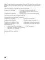
1. APPLICATION .................................................................................... 5
2. DESCRIPTION OF THE MODBUS PROTOCOL ................................ 5
2.1. ASCII framing ........................................................................................... 7
2.2. RTU framing ............................................................................................. 7
2.3. Characteristic of frame field ................................................................... 8
2.4. LRC checking ........................................................................................... 9
2.5. CRC checking .......................................................................................... 9
2.6. Character format in series transmission ............................................. 10
2.7. Transaction interruption ....................................................................... 10
3. DESCRIPTION OF FUNCTIONS ...................................................... 10
3.1. Readout of N-registers (Code 03) ........................................................ 11
3.2. Writing of values in the register (Code 06) .......................................... 11
3.3. Writing in N-registers (Code 16) ........................................................... 12
3.4. Report identifying the device (Code 17) Requirement ....................... 12
4. ERROR CODES ................................................................................ 13
5. TABLE OF REGISTERS ................................................................... 15
AFFIX A. CALCULATION OF THE CHECKSUM ................................. 23
3
4
1. APPLICATION
In order to obtain the information exchange, when using the serial link, one must
choose the interface type and validate the interpretation way of transmitted data. The
interface type defines only electrical transmission parameters and the way of the
device connection.
Such features, as the possibility to service several devices, check the transmission
correctness and the principles of access to the device, depend on the data interpretation.
The task of the protocol is to define which data is interpreted (permitted) and in which
way they are interpreted.
A MODBUS asynchronous character transmission protocol has been implemented
on the serial link of the KR7 recorder. The parameter configuration of the RS-485
serial link is described in the KR7 recorder service manual.
Parameter set of the KR7 recorder serial link:
Recorder address
1 ...247
Baud rate
300, 600, 1200, 1200, 2400, 4800, 9600, 14400,
19200, 28800, 38400, 57600, 115200 bit/s
Mode
ASCII, RTU
Information unit
ASCII: 8N1, 7N2, 7E1, 701
RTU:8N2, 8N1, 8E1,8O1
Maximal turnaround time
100 ms (400 ms, in case of parameter writing)
2. DESCRIPTION OF THE MODBUS PROTOCOL
The MODBUS interface is a standard adopted by manufacturers of industrial devices
for the asynchronous character exchange of information between different devices
and measuring systems. It has such features as:
Simple access rule to the link based on the master-slave principle,
Protection of transmitted messages against errors,
Confirmation of remote instruction realization and error signaling,
Effective actions protecting against the system suspension,
Taking advantage of the asynchronous character transmission.
Device controllers working in the MODBUS protocol can communicate with each other,
taking advantage of the master-slave protocol type, in which only one device
(the master - superior unit) can originate transactions (called queries), and others
(slaves - subordinate units) respond only to the remote requested data from the
master. The transaction is composed of the transmitted command from the master
unit to the slave unit and of the response transmitted in the opposite direction.
The response includes data demanded by the master or the confirmation of the
command realization.
5
Master can transmit information to individual slaves or broadcast messages destined
for all subordinate devices in the system (responses are not returned to broadcast
queries from the master).
The format of transmitted information is as following:
master => slave: device address, code representing the required command,
data to be sent, control word protecting the transmitted
message,
slave => master: sender address, confirmation of the command realization,
data required by the master, control word protecting
the response against errors.
If the slave device detects an error when receiving a message, or cannot realize the
command, it prepares a special message about the error occurrence and transmits it
as a response to the master.
Devices working in the MODBUS protocol can be set into the communication using
one of two transmission modes: ASCII or RTU. The user chooses the required mode,
along with the serial port communication parameters (baud rate, information unit)
during the configuration of any device.
In the MODBUS system, transmitted messages are placed into frames that are not
related to serial transmission. These frames have a defined beginning and end. This
enables the receiving device to reject incomplete frames and signal related errors with
them.
Taking into consideration the possibility to operate in one of these two different
transmission modes (ASCII or RTU), two frames have been defined.
Explanation of some abbreviations:
ASCII
= American Standard Code for Information Interchange
RTU
= Remote Terminal Unit
LRC
= Longitudinal Redundancy Check
CRC
= Cyclic Redundancy Check
CR = Carriage Return
LF = Line-Feed (character)
MSB
= Most Significant Bit
Checksum = Control Sum
6
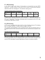
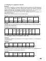
2.1. ASCII framing
In the ASCII mode each byte of information is transmitted as two ASCII
characters. The basic feature of this mode is that it allows to long intervals between
characters within the message (to 1 sec) without causing errors.
A typical message frame is shown below.
Start beginning
index
1 char
/:/
Address
Function
Data
2 chars
2 chars
n chars
LRC
check
2 chars
End
index
2 chars
CR LF
In ASCII mode, messages start with a colon character (: -ASCII 3Ah) and end with
CR and LF characters. The frame information part is protected by the LRC code
(Longitudinal Redundancy Check).
2.2. RTU Framing
In RTU mode, messages start and end with an interval lasting minimum 3.5 x (lasting
time of a single character), in which a silence reigns on the link.
The simplest implementation of the mentioned time interval character times is
a multiple measure of the character duration time at the set baud rate accepted on the
link.
The frame format is shown below:
Start beginning
index
T1-T2-T3-T4
Address
Function
Data
CRC check
End index
8 bits
8 bits
n x 8bits
16 bits
T1-T2-T3-T4
Start and end indexes are marked symbolically as an interval equal to four lengths of
the index (information unit). The checking code consists of 16 bits and emerges as the
result of CRC calculation (Cyclical Redundancy Check) of the frame contents.
7
2.3. Characteristic of frame fields.
Address field
The address field of a message frame contains two characters (in ASCII mode) or
eight bits (in RTU mode).
Valid slave device addresses are in the range from 0 -247 . The master addresses the
slave unit by placing the slave address in the frame address field. When the slave
sends its response, it places its own address in the frame address field what enables
the master to check which slave is responding.
The 0 address is used as a broadcast address recognized by all slave units connected
to the bus.
Function field
The function code field of a message frame contains two characters in ASCII mode or
eight bits in RTU mode. Valid codes are in the range from 1 - 255.
When a message is sent from a master to a slave device, the function code field tells
the slave what kind of action to perform.
When the slave responds to the master, the function field is used to confirm the
command execution or error signaling if the function code field cannot realize the
command for any reason. to indicate either a normal (error-free) response or that
some kind of error occurred.
The positive confirmation is realized through the placement of the command
execution code on the function field.
In case of an error assertion, the slave returns a special code that is equivalent to the
original function code with its most significant logic 1.
The error code is placed on the data field of the response frame.
Data field
The data field is constructed using sets of two hexadecimal digits, in the range of 00 to
FF. These can be made from a pair of ASCII characters or from one RTU character,
according to the networks serial transmission mode. The data field of messages sent
from a master to slave devices contains additional information which the slave must
use to take the action defined by the function code. This can include items like register
addresses, number of bytes in data field , data, a.s.o. The data field can be
non-existent (of zero length) in certain kinds of frames. That occurs always when the
operation defined by the code does not require any parameters.
Error checking field
Two kinds of error-checking methods are used for standard MODBUS networks.
The error checking field contents depends upon the method that is being used.
ASCII
When ASCII mode is used for character framing, the error checking field contains two
ASCII characters. The error check characters are the result of a Longitudinal Redundancy Check (LRC) calculation that is performed on the message contents (without
the beginning «»colon and terminating CRLF characters). LRC characters are
appended to the message, as the last field preceding the CR, LF characters.
8
RTU
When RTU mode is used for character framing, the error checking field contains
a 16-bit value implemented as two 8-bit bytes. The error check value is the result of
a Cyclical Redundancy Check Calculation (CRC) performed on a message contents.
The CRC field is appended to the message as the last field in the message. When this
is done, the low-order byte of the field is appended first, followed by the high-order
byte. The CRC high-order byte is the last byte to be sent in the message.
2.4. LRC checking
The LRC is calculated by adding together successive 8-bit bytes of the message,
discarding any carries, and then two is complementing the result. It is performed
on the ASCII message field contents excluding the,,colon character that begins the
message, and excluding the CR, LF pair at the end of the message. The 8-bit value of
the LRC sum is placed at the frame end as two ASCII characters, first the character
containing the higher tetrad, and after it, the character containing the lower LRC
tetrad.
2.5. CRC checking
The generating procedure of CRC is realized according to the following algorythm:
1.
Load a 16-bit register with FFFFh. Call this the CRC register.
2.
Exclusive OR the first 8-bit byte of the message with the low-order byte
of the 16 bit CRC register, putting the result in the CRC register.
3.
Shift the CRC register one bit to the right (towards the LSB), zero-filling
the MSB. Extract and examine the LSB.
4.
(If the LSB was O): Repeat step 3 (another shift) (If the LSB was 1):
Exclusive OR the CRC register with the polynomial value A001h.
5.
Repeat steps 3 and 4 until 8 shifts have been performed. When this is done,
a complete 8-bit byte will have been processed.
6.
Repeat steps 2 through 5 for the next 8-bit byte of the message.
Continue doing this until all bytes have been processed.
7.
The final contents of the CRC register is the CRC value.
8.
When the CRC is placed into the message, its upper and lower bytes
must be swapped as described below.
9
2.6. Character format during serial transmission
In the MODBUS protocol, characters are transmitted from the lowest to the highest
bit. Organization of the information unit in the ASCII mode:
1 start bit,
7 data field bits,
1 even parity check bit (odd) or lack of even parity check bit,
1 stop bit at even parity check or 2 stop bits when lack of even parity check.
Organization of the information unit in the RTU mode:
1 start bit,
8 data field bits,
1 even parity check bit (odd) or lack of even parity check bit,
1 stop bit at even parity check or 2 stop bits when lack of even parity check.
2.7. Transaction interruption
In the master unit the user sets up the important parameter which is the maximal
response time on the query frame after exceeding of which, the transaction is
interrupted. This time is chosen such that each slave unit working in the system (even
the slowest) normally will have the time to answer to the frame query. An exceeding of
this time attests therefore about an error and such is treated by the master unit.
If the unit slave will find out a transmission error it does not accomplish the order and
does not send any answer. That causes an exceeding of the waiting time after the
query frame and the transaction interruption.
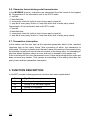
3. FUNCTION DESCRIPTION
In the KR7 recorder following protocol functions has been implemented:
Code
10
Signification
03
Reading of n-register
06
Writing of an individual register
16
Writing of n-registers
17
Slave device identification
3.1. Reading of n-registers (code 03)
Demand:
The function enables the reading of values included in registers in being addressed
slave device. Registers are 16 or 32-bit units, which can include numerical
values bounded with changeable processes, and the like. The demand frame
defines the 16-bit start address and the number of registers to read-out.
The signification of the register contents with address data can be different for
different device types.
The function is not accessible in the broadcast mode.
Example: Reading of 3 registers beginning by the register with the 6Bh address.
Address
Function
11
03
Register Register
address address
Hi
Lo
00
6B
Number of
Number of
Checksum
registers
Hi
00
registers
Lo
03
7E
LRC
Answer:
Register data are packing beginning from the smallest address: first the higher byte,
then the lower register byte.
Example: the answer frame
Address Function Number
of bits
regist
107
Hi
11
03
06
Value
in the
regist
107
Lo
02
Value
in the
regist
108
Hi
2B
Value
in the
regist
108
Lo
00
Value
in the
regist
109
Hi
00
Value Value Checksum
in the in the
regist
109
Lo
00
64
55
LRC
3.2. Writing of values in the register (code 06)
Demand:
The function enables the modification of the register contents. It is accessible in
broadcast mode.
Example:
Address Function
11
06
Register
address
Hi
00
Register
address
Lo
87
Value
Hi
Value
Lo
Checksum
03
9E
C1
LRC
Answer:
The correct answer to a value record demand in the register is the retransmission of
the message after accomplishing the operation.
Example:
Address
Function
11
06
Register
address
Hi
00
Register
address
Lo
87
Value
Hi
Value
Lo
Checksum
03
9E
C1
LRC
11
3.3. Writing in n-registers (code 16)
Demand:
The function is accessible in broadcast mode. It enables the modification of the
register contents.
Example: Writing of two registers beginning from the register addressed 136.
Address Function Register Register Number
address address of
Hi
Lo
registers
Hi
11
10
00
87
00
Number
of
registers
Lo
02
Number Data Data Data Data Checksum
of
Hi
Lo Hi
Lo
bytes
04
00
0A
01
02
45
LRC
Answer:
The correct answer includes the unit slave address, function code, starting address
and the number of recorded registers.
Example:
Address
11
Function Register
address
Hi
10
00
Register
address
Lo
87
Number of
registers
Hi
00
Number of
registers
Lo
02
Checksum
56
LRC
3.4. Report identifying the device (code 17)
Demand:
This function enables the user to obtain information about the device type, status and
configuration depending on this.
Example
Address
11
Function
11
Checksum
DE
LRC
Answer:
The field ,,Device identifier in the answer frame means the unique identifier of this
class of device, however the other fields include parameters depended on the device
type.
Example concerning the KR7 recorder
Slave
address
Function
Number
of bytes
Device
identifier
Device state
Checksum
11
11
2
77
FF
66
12
4. ERROR CODES
When the master device is broadcasting a demand to the slave device then, except
for messages in the broadcast mode, it expects a correct answer. After sending the
demand of the master unit, one of the four possibilities can occur:
If the slave unit receives the demand without a transmission error and can execute
it correctly, then it returns a correct answer,
If the slave unit does not receive the demand, no answer is returned. Timeout
conditions for the demand will be fulfilled in the master device program.
If the slave unit receives the demand, but with transmission errors (even parity error
of checking sum LRC or CRC), no answer is returned. Timeout condition for the
demand will be fulfilled in the master device program.
If the slave unit receives the demand without a transmission error but cannot
execute it correctly (e.g. if the demand is, the reading-out of a non-existent bit
output or register), then it returns the answer including the error code, informing the
master device about the error reason.
A message with an incorrect answer includes two fields distinguishing it from the
correct answer.
1. The function code field:
In the correct answer, the slave unit retransmits the function code from the demand
message in the field of the answer function code. All function codes have the
most-significant bit (MSB) equal zero (code values are under 80h). In the incorrect
answer, the slave unit sets up the MSB bit of the function code at 1. This causes that
the function code value in the incorrect answer is exactly of 80h greater than it would
be in a correct answer.
On the base of the function code with a set up MSB bit the program of the master
device can recognize an incorrect answer and can check the error code on the data
field.
2. The data field:
In a correct answer the slave device can return data to the data field (certain information required by the master unit). In the incorrect answer the slave unit returns the
error code to the data field. It defines conditions of the slave device which had produced the error. An example considering a demand of a master device and the incorrect
answer of the slave unit has been shown below. Data are in the hexadecimal shape.
Example: demand
Slave
Function
address
Variable
address
H1
Variable
address
Lo
Number
of
variables
Hi
Number
of
variables
Lo
Checksum
OA
04
A1
00
01
4F
01
LRC
Example: incorrect answer
Slave
Function
Error
Checksum
OA
81
02
73
LRC
13
In this example the master device addresses the demand to the slave unit with No10
(OAh). The function code (01) serves to the read-out operation of the bit input state.
Then, this frame means the demand of the status read-out of a one bit input with the
address number: 1245 (04A1h).
If in the slave device there is no bit input with the given address, then the device
returns the incorrect answer with the No 02 error code. This means a forbidden data
address in the slave device.
Possible error codes and their meanings are shown in the table below.
Code
14
Meaning
01
Forbidden function
02
Forbidden data address
03
04
05
06
07
08
Forbidden data value
Damage in the connected device
Confirmation
Occupied, message removed
Negative confirmation
Error of memory parity
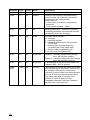
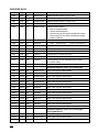
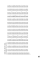
5. TABLE OF REGISTERS
KR7 recorder identifier (set as a response to the identification function) : 0x83
Type of registers (type column)
- int - 16-bit number
- long - 32 bit number
- float - floating point number (see the description below)
- sfloat - floating point number (see the description below)
- str[n] - sequence of characters with a maximal length of n characters,
ended by a character with 0 code (together with the character of the
end, the sequence of characters has n+1 length
Access mode to registers
- RW - for read-out and writing
- RO - for read-out only
- WO - for writing only
Representation of floating point numbers (float IEEE 754)
byte: 0
MMMMMMMM
1
MMMMMMMM
2
EMMMMMMM
3
SEEEEEEE
S - character bit (Sign bit)
E - exponent
M - mantissa
Register bytes of float type are sent in 3210 sequence
Register bytes of sfloat type are sent in 1032 sequence
15
Address
Type
Access
Name
Description
Control registers
4000
int
RW
RSpass
Writing a value equal to the password set
in the recorder will cause the unlocking of
the access to the setting writing.
When read-out:
- if the access is unlocked - programmed
password
- if the access is locked - 10000.
4001
int
RW
Init
Writing of any value - execution of recorder
initializing (should be done after the recorder
parameters have been changed.)
4002
int
RW
Mode
Recorder working mode:
0 - recording
1 - recording stopped
2 - recording stopped by the binary signal
(STOP BIN)
3 - marking of the recorder beginning
(horizontal line on the paper tape)
4 - service mode (noupdatepomval)
5- service mode (noupdateoutval)
4003
int
RW
GoMinMax
Writing 0 - recording stopped and carriage
set in the minimum position
Writing 1 - recording stopped and the carriage
set in the maximum position
4004
int
RO
isPrintText
The realization of the text printout order from
registers 4005...4015 is going on.
4005...
4015
Str[21] RW
PrintText
Text printout, the writing will cause the printout
of the written text. If the printout order will not
be accepted, then the error code will be
returned ( the error code is not returned when
the text will not be printed because of a too
high paper tape feed or because of the
printout of a task of higher priority).
Admissible character codes are inserted in
the KR7 users manual (p.18)
16
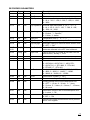
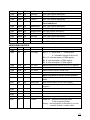
RECORDER PARAMETERS
Address Type Access Name
Description
System parameters
4110
int
RW
Sys.Pass
Password
4111
int
RW
SysSpeed
Internal tape feed speed: 0 - 0, 1 - 5, 2 - 10,
3 - 20, 4 - 60, 5 - 120, 6 - 300, 7 - 600, 8 - 1200,
9 - 3600.
4112
int
RW
Sys.SpeedExt External tape feed speed: 0 - off, 1 - 0, 2 - 5,
3 -10, 4 - 20, 5 - 60, 6 - 120, 7 - 300, 8 - 600,
9 - 1200, 10 - 3600.
4113
int
RW
Sys.Lang
Menu description language:
0 - English, 1 - German,
2 - French, 3 - Italien
4114
int
RW
Syst.Unit
Temperature unit: 0 - oC, 1 - oF
4115
int
RW
Syst.Freq
Supplying network frequency: 0 - 50 Hz, 1 - 60 Hz
4116
int
RW
Sys.Daylight
Automatic change of summer/winter season time:
0 - OFF, 1 - ON
4117...
4121
Str[8] RW
Sys.ScaUnit
Scale description unit. Admissible character
codes are inserted in the KR7 Users Manual.
4122
Long RW
Syst.Time
Time in the form of number of seconds from the
0:00:00 hour, January 1, 1970
4123
-
-
-
4140
int
RW
Int.Mode
Parameters of the communication interface
Transmission mode:
0 - ASCII 8N1, ASCII 7N2, 2 - ASCII 7E1,
3 - ASCII 7O1, 4 - RTU 8N2, 5 - RTU 8N1,
6 - RTU 8E1, 7 - RTU 801
4141
int
RW
Int.Baud
4142
int
RW
Int.ID
Baud rate: 0 - 300, 1 - 600, 2 - 1200, 3 - 2400,
4 - 4800, 5 - 9600, 6 - 14400, 7 - 19200,
8 - 28800, 9 - 38400, 10 - 115200
Identification number (1...247)
Parameters of tape description
4150
int
RW
Printing period of the current description line:
0 - OFF, 1 - 15 min, 2 - 30 min, 3 - 1 hour,
4 - 2 hours, 5 - 3 hours, 6 - 6 hours, 7 - 12 hours,
8 - 24 hours.
4151
int
RW
Information range in the current description line:
0 - in short, 1 - full
4152
int
RW
Tape description after alarm occurrence:
0 -OFF, 1 - ON
4153
int
RW
Period of the digital measurement result printout:
as for 4150 register
17
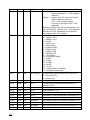
Measuring parameters
4170
int
RW
M.RW
Writing 0 - read-out of the M.record (one must
execute before 4171...4187 registers
read-out)
Writing 1 - writing of the M. record (one must
execute after the writing of
4171...4187 registers writing
or writing in group the 4170...4187
registers)
Before the writing of the M. record (writing 1 into
the 4170 register), values in 4171...4187 registers
should be correct, admissible for the defined
input signal in the 4171 register.
4171
int
RW
M.Type
Kind of input signal:
0 - Voltage < 10 V
1 - Voltage > 10 V
2 - Current
3 - J (FeCu-Ni)
4 - K (NiCr-NiAl)
5 - N (NiCrSi-NiSi)
6 - E (NiCr-CuNi)
7 - R (PtRh13-Pt)
8 - S (PtRh10-Pt)
9 - T (Cu-CuNi)
10 - B (PtRh30-PtRh6)
11 - Pt100
12 - Pt500
13 - Pt1000
14 - Ni100
15 - Cu100
16 - Potentiometric transmitter
17 - Resistance transmitter
4172
int
RW
M.CompTyp
Compensation type of reference cold junction:
0 - internal (ACJC)
1 - external (CJ)
4173
-
-
-
4174
float
RW
M.CJ
4175
-
-
-
4176
float
RW
M.LR
4177
-
-
-
4178
float
RW
M.PR
4179
-
-
-
4180
float
RW
M.InpMin
4181
-
-
-
4182
float
RW
M.InpMax
4183
-
-
-
18
Temperature of external compensation (CJ)
(always in 0oC)
Line resistance [9]
Resistance of the potentiometric transmitter [9]
Input signal minimum (temperature always in oC)
Input signal maximum (temperature always in oC)
4184
float
RW
M.ScaMin
4185
-
-
-
4186
float
RW
M.ScaMax
4187
-
-
-
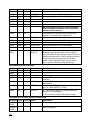
4190
int
RW
LOut.RW
Scale description - min
Scale description - max
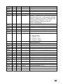
Parameters of the retransmission output
Writing 0 - read-out of the LOutrecord (must be
executed before 4191...4196 registers read-out)
Writing 1 - writing of the LOut. record (must be
executed after the writing of 4191...4196
registers writing or writing in group the
4190...4196 registers)
4191
-
-
4192
float
RW
LOut.Min
4193
-
-
-
4194
float
RW
LOut.Max
4195
-
-
-
4196
int
RO
Lout.Type
Minimal retransmission signal
Maximal retransmission signal
Type of the retransmission output:
0 - without output
1 - Voltage 0 -10 V
2 - Current 0...5 mA
3 - Current 0...20 mA
Alarm parameters
4200
float
RW
Ala.Val[0]
4201
-
-
-
4202
float
RW
Ala.Hyst[0]
4203
-
-
-
4204
int
RW
Ala.Act[0]
4205
-
-
-
Relay 1 - Value of the alarm threshold
Relay 1 - Alarm hysteresis
Relay 1 - Alarm activity (0 - OFF., - ON)
4206
float
RW
Ala.Val[1]
4207
-
-
-
Relay 2 - Alarm threshold value
4208
float
RW
Ala.Hyst[1]
4209
-
-
-
4210
int
RW
Ala.Act[1]
Relay 2 - Alarm activity (0 -OFF, 1 - ON)
4220
int
RW
Cal.Min
Recorder calibration - 0%
4221
int
RW
Cal.Max
Recorder calibration - 100%
4222
int
RW
CalSave
Writing 1 - writing of calibrating parameters
Relay 2 - Alarm hysteresis
Recorder calibration parameters
19
PROCESS DATA
Address Type Access Name
Description
7000
float
RO
Measurement value in input units
7001
-
-
-
7002
float
RO
MeasureSca
7003
-
-
-
7004
float
RO
MeasureStat
MeasureInp
Measurement value in scale units
Measurement status:
0 - lack of measurement
1 - correct measurement
2 - overrunning of the upper transducer range
3 - overrunning of the lower transducer range
4 - break of sensor
7005
-
-
-
7006
float
RO
Ala0Stat
7007
-
-
-
7008
float
RO
Ala1Stat
7009
-
-
-
7010
float
RO
TempCJ
7011
-
-
-
7012
float
RW
LineOut
7013
-
-
-
7100
sfloat RO
MeasureInp
7101
-
-
7102
sfloat RO
7103
-
7104
sfloat RO
MeasureStat
7105
-
-
-
7106
sfloa
tRO
Ala0Stat
7107
-
-
-
0 - relay 1 switched off. 1 - relay 2 switched on
0 - relay 2 switched off. 1 - relay 1 switched on
Temperature of cold junctions
Controllability of the retransmission output
(in output units)
Doubled registers 7000..7013, float type
-
MeasureSca
sfloat RO
Ala1Stat
7109
-
-
7110
sfloat RO
TempCJ
7111
-
-
7112
sfloat RW
LineOut
7113
-
-
-
See 7002 register description
-
7108
-
See 7000 register description
See 7004 register description
See 7006 register description
See 7008 register description
See 7010 register description
See 7012 register description
Doubled registers 7000..7013, float type,
32-bit addressed
7500
float
RO
MeasureInp
See 7000 register description
7501
float
RO
MeasureSca
See 7002 register description
7502
float
RO
MeasureStat
See 7004 register description
20
7503
float
RO
Ala0Stat
See 7006 register description
7504
float
RO
Ala1Stat
See 7008 register description
7505
float
RO
TempCJ
See 7010 register description
7506
float
RW
LineOut
See 7012 register description
Doubled registers 7000..7013, sfloat type,
32-bit addressed
7600
sfloat RO
MeasureInp
See 7000 register description
7601
sfloat RO
MeasureSca
See 7002 register description
7602
sfloat RO
MeasureStatS ee 7004 register description
7603
sfloat RO
Ala0Stat
See 7006 register description
See 7008 register description
7604
sfloat RO
Ala1Stat
7605
sfloat RO
TempCJ
See 7010 register description
7606
sfloat RW
LineOut
See 7012 register description
MEASURING BUFFER
Current value of measurement and time
7994
-
-
-
7995
int
RO
Cur.Flags
Bit 0..1: 0 - winter time, 1 - summer time,
2 - automatic change of time is off
Bit 8..10: see description of 7004 register
Bit 12: see description of 7006 register
Bit 13: see description of 7008 register
7996
long
RO
Cur.Time
7997
-
-
-
7998
float
RO
Cur.Value
7999
-
-
-
8000
int
RO
PosNew
Measurement time (format as for 4112 register)
Measurement value in scale units
Measuring buffer from the newest position
Position of the newest data in the measuring
buffer
8001
int
RO
New.Flags
See the description of the 7995 register
8002
long
RO
New.Time
Measurement time (format as for the 4122
register)
8003
-
-
-
8004
float
RO
New.Value
8005
-
-
-
8006
int
RO
PosNew
See the description of the 8000 register
8007
int
-
PosOld
Read-out - position of the higher data
in the measuring buffer.
Measurement value in scale units
Writing - set the position in the buffer (n) on the
position PosOld + written value.
21
Measuring buffer from the selected position
8008
int
RW
n
Position in the buffer
8009
int
RO
Buf[n].Flags
See the description of the 8001 register
8010
long
RO
Buf[n].Time
See the description of the 8002 register
8011
-
-
-
8012
float
RO
Buf[n].Value
8013
-
-
-
See the description of the 8004 register
Measuring buffer from the selected position,
with automatic transition on the next buffer
position while read out
8014
int
RO
n
The position in the buffer, while read out this
register is automatically increased of 1
8015
int
8016
long
RO
Buf[n].Flags
See the description of the 8001 register
RO
Buf[n].Time
8017
-
-
-
See the description of the 8002 register
8018
float
RO
Buf[n].Value
8019
-
-
-
8020...
8074
Buf[n+1]...
Buf[n+9]
See the description of the 8004 register
8014...8019 registers are nine time repeated.
Reading out by groups 8008...8074 registers,
one can obtain 10 successive positions from the
measuring buffer (8014...8074 registers) and the
contents of the previously read out position
(8008...8013) registers) which we can used
e.g. in order to check the data continuity)
INFORMATION REGISTERS
Address Type Access Name
Description
9000
9001
9002
9003
ulong
int
int
RO
RO
RO
SerialNb
Version
SetupIsData
Recorder serial number
9004
int
RO
CalibIsData
9005
int
RW
EEPROMstat
9006
int
RO
IsPrinter
KR7 programming version (version *1000)
1 - in the Flash memory there are parameters
on order
1 - in the Flash memory there are calibrating
parameters
State of the EEPROM memory:: 0x1234 - OK.,
0x1111 - BAD, 0xFFFF - Empty
0 - The recorder does not includes the printer
module or it is damaged
1 - the recorder includes the printer module.
TECHNOLOGICAL AND SERVICE REGISTERS
Address Type Access Name
Description
9200...
9252
-
-
-
Technological registers
30000...
30001
-
-
-
Service registers
22
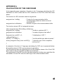
APPENDIX A
CALCULATION OF THE CHECKSUM
In this appendix some examples of function in the C language calculating the LRC
checksum for ASCII mode and the CRC checksum for the RTU mode have been
shown.
The function for LRC calculation has two arguments:
unsigned char *outMsg;
unsigned short usDataLen;
- Pointer for the communication buffer,
including binary data from which one must
calculate LRC.
- Number of bytes in the communication buffer.
The function returns LRC of unsigned char type.
static unsigned char LRC(outMsg, usDataLen)
unsigned char *outMsg;
/* buffer to calculate LRC */
unsigned short usDataLen;
/* number of bytes in the buffer 7
{
unsigned char uchLRC = 0;
/* initialization of LRC */
while (usDataLen)
uchLRC += *outMsg++;
/* add the buffer byte without transfer*
return ((unsigned char)(-(char uchLRC)));
/* return the sum in the completion
code up two*/
}
An example of function in C language calculating the CRC sum is presented below.
All possible values of CRC sum are placed in two tables.
The first table includes the highest byte of all 256 possible values of the 16-bit CRC
field, however the second table includes the lowest byte.
The assignment of the CRC sum through table indexing is further more rapid than the
calculation of a new CRC value for each sign of the communication buffer.
23
Note: The below function represents bytes of the sum CRC higher/lower, and this way
the CRC value returned by the function can be directly placed in the communication
buffer.
The function serving to calculate CRC has two arguments:
unsigned char *puchMsg;
unsigned short usDataLen;
- Pointer for the communication buffer,
including binary data from which one must
calculate LRC.
- Number of bytes in the communication buffer.
The function returns CRC of unsigned short type.
unsigned short CRC16(puchMsg, usDataLen)
unsigned char *puchMsg;
/* buffer to calculate CRC */
unsigned short usDataLen;
/*Number of bytes in the buffer */
{
unsigned char uchCRChi = OxFF;
/* initialisation of the higher CRC byte*/
unsigned char uchCRCIo = OxFF;
/* initialisation of the lower CRC byte */
while (usDataLen)
{
uindex = uchCRChiA *puchMsg++;
/* CRC calculation*/
uchCRChi = uchCRCIo A crc_hi[ulndex];
uchCRCIo = crc_lo[ulndex];
}
retum(uchCRChi8 \ uchCRCIo);
}
24
25
0x00,
0x40,
0x80,
0xC0,
0x00,
0x40,
0x80,
0xC0,
0x00,
0x40,
0x80,
0xC0,
0x00,
0x40,
0x80,
0xC0,
0x00,
0x40
};
0xC1,
0x01,
0x41,
0x80,
0xC1,
0x01,
0x41,
0x80,
0xC1,
0x00,
0x41,
0x80,
0xC1,
0x01,
0x41,
0x80,
0xC1,
0x81,
0xC0,
0x01,
0x41,
0x81,
0xC0,
0x00,
0x41,
0x81,
0xC1,
0x01,
0x41,
0x81,
0xC0,
0x00,
0x41,
0x81,
0x40,
0x80,
0xC0,
0x00,
0x40,
0x80,
0xC1,
0x00,
0x40,
0x81,
0xC0,
0x01,
0x40,
0x80,
0xC1,
0x00,
0x40,
//table of the older CRC byte /
const unsigned char crc_hi[]={
0x01,
0x41,
0x80,
0xC1,
0x01,
0x41,
0x81,
0xC1,
0x01,
0x40,
0x80,
0xC0,
0x00,
0x41,
0x81,
0xC1,
0x01,
0xC0,
0x00,
0x41,
0x81,
0xC0,
0x00,
0x40,
0x81,
0xC0,
0x01,
0x41,
0x80,
0xC1,
0x01,
0x40,
0x81,
0xC0,
0x80,
0xC1,
0x00,
0x40,
0x80,
0xC1,
0x00,
0x40,
0x80,
0xC0,
0x00,
0x41,
0x81,
0xC0,
0x00,
0x40,
0x80,
0x41,
0x81,
0xC1,
0x01,
0x41,
0x81,
0xC1,
0x01,
0x41,
0x80,
0xC1,
0x00,
0x40,
0x80,
0xC1,
0x00,
0x41,
0x01,
0x40,
0x81,
0xC0,
0x00,
0x40,
0x81,
0xC0,
0x01,
0x41,
0x81,
0xC1,
0x01,
0x41,
0x81,
0xC1,
0x01,
0xC0,
0x00,
0x40,
0x80,
0xC1,
0x01,
0x40,
0x80,
0xC0,
0x00,
0x40,
0x81,
0xC0,
0x00,
0x40,
0x81,
0xC0,
0x80,
0xC1,
0x00,
0x41,
0x81,
0xC0,
0x01,
0x41,
0x80,
0xC1,
0x00,
0x40,
0x80,
0xC1,
0x01,
0x40,
0x80,
0x41,
0x81,
0xC1,
0x01,
0x40,
0x80,
0xC0,
0x00,
0x41,
0x81,
0xC1,
0x01,
0x41,
0x81,
0xC0,
0x01,
0x41,
0x00,
0x40,
0x81,
0xC0,
0x00,
0x41,
0x80,
0xC1,
0x00,
0x40,
0x81,
0xC0,
0x00,
0x40,
0x80,
0xC0,
0x00,
0xC1,
0x01,
0x40,
0x80,
0xC1,
0x01,
0x41,
0x81,
0xC1,
0x01,
0x40,
0x80,
0xC1,
0x01,
0x41,
0x80,
0xC1,
0x81,
0xC0,
0x01,
0x41,
0x81,
0xC0,
0x01,
0x40,
0x81,
0xC0,
0x01,
0x41,
0x81,
0xC0,
0x01,
0x41,
0x81,
26
0x00,
0x04,
0x08,
0x1D,
0x11,
0x37,
0x3B,
0x2E,
0x22,
0x62,
0x6E,
0x7B,
0x77,
0x51,
0x5D,
0x48,
0x44,
0x40
};
0xC0,
0xCC,
0xC8,
0x1C,
0xD1,
0xF5,
0xFB,
0x2F,
0xE2,
0x66,
0xAE,
0x7A,
0xB7,
0x93,
0x9D,
0x49,
0x84,
0xC1,
0x0C,
0xD8,
0xDC,
0xD0,
0x35,
0x39,
0xEF,
0xE3,
0xA6,
0xAA,
0xBA,
0xB6,
0x53,
0x5F,
0x89,
0x85,
0x01,
0x0D,
0x18,
0x14,
0x10,
0x34,
0xF9,
0x2D,
0x23,
0xA7,
0x6A,
0xBE,
0x76,
0x52,
0x9F,
0x4B,
0x45,
//table of the lower CRC byte /
const unsigned char crc_lo[]={
0xC3,
0xCD,
0x19,
0xD4,
0xF0,
0xF4,
0xF8,
0xED,
0xE1,
0x67,
0x6B,
0x7E,
0x72,
0x92,
0x9E,
0x8B,
0x87,
0x03,
0x0F,
0xD9,
0xD5,
0x30,
0x3C,
0x38,
0xEC,
0x21,
0xA5,
0xAB,
0x7F,
0xB2,
0x96,
0x5E,
0x8A,
0x47,
0x02,
0xCF,
0x1B,
0x15,
0x31,
0xFC,
0x28,
0x2C,
0x20,
0x65,
0x69,
0xBF,
0xB3,
0x56,
0x5A,
0x4A,
0x46,
0xC2,
0xCE,
0xDB,
0xD7,
0xF1,
0xFD,
0xE8,
0xE4,
0xE0,
0x64,
0xA9,
0x7D,
0x73,
0x57,
0x9A,
0x4E,
0x86,
0xC6,
0x0E,
0xDA,
0x17,
0x33,
0x3D,
0xE9,
0x24,
0xA0,
0xA4,
0xA8,
0xBD,
0xB1,
0x97,
0x9B,
0x8E,
0x82,
0x06,
0x0A,
0x1A,
0x16,
0xF3,
0xFF,
0x29,
0x25,
0x60,
0x6C,
0x68,
0xBC,
0x71,
0x55,
0x5B,
0x8F,
0x42,
0x07,
0xCA,
0x1E,
0xD6,
0xF2,
0x3F,
0xEB,
0xE5,
0x61,
0xAC,
0x78,
0x7C,
0x70,
0x95,
0x99,
0x4F,
0x43,
0xC7,
0xCB,
0xDE,
0xD2,
0x32,
0x3E,
0x2B,
0x27,
0xA1,
0xAD,
0xB8,
0xB4,
0xB0,
0x94,
0x59,
0x8D,
0x83,
0x05,
0x0B,
0xDF,
0x12,
0x36,
0xFE,
0x2A,
0xE7,
0x63,
0x6D,
0xB9,
0x74,
0x50,
0x54,
0x58,
0x4D,
0x41,
0xC5,
0xC9,
0x1F,
0x13,
0xF6,
0xFA,
0xEA,
0xE6,
0xA3,
0xAF,
0x79,
0x75,
0x90,
0x9C,
0x98,
0x4C,
0x81,
0xC4,
0x09,
0xDD,
0xD3,
0xF7,
0x3A,
0xEE,
0x26,
0xA2,
0x6F,
0xBB,
0xB5,
0x91,
0x5C,
0x88,
0x8C,
0x80,
27
tel.: (48-68) 32 95 100
fax: (48-68) 32 95 101
e-mail: [email protected]
http://www.lumel.com.pl
28
Export Department:
tel. or fax: (48-68) 32 54 091
e-mail: [email protected]
LUMEL S.A., January 2004
Lubuskie Zak³ady Aparatów Elektrycznych LUMEL S.A.
ul. Sulechowska 1
65-950 Zielona Góra - Poland