1
HD710 User Manual
(0.4kW~11kW P)
V1.4
Foreword
Thank you for using HD710 AC drives made by Guangzhou HEDY Industrial Automation
CO., Ltd.
This manual introduces installation, setup and commissioning of HD710 Drive, also
troubleshoot and maintenance.
We will update the manual to improve it termly, and the contents in this document are subject
to change without notice.
Copyright © 2011 by Guangzhou HEDY Industrial Automation CO., Ltd.
All rights reserved.
Please read the information carefully, and keep the manual, please make sure that the end
customer has the manual.
Contents
1
Technical specification ..........................................................................................................1
1.1 Model reference ..........................................................................................................1
1.2 Rating label.................................................................................................................1
1.3 Power size...................................................................................................................2
1.4 General technical data.................................................................................................3
2
Installation and cabling ..........................................................................................................5
2.1 Dimension ..................................................................................................................5
2.1.1 Parts of drive ................................................................................................... 5
2.1.2
Diagram of mounting ...................................................................................... 5
2.1.3
Display panel pallet ........................................................................................ 6
2.1.4
Simple display panel pallet ............................................................................. 8
2.2 Mechanical installation ...............................................................................................9
2.2.1
Drive installation diagram............................................................................... 9
2.2.2
Fit and remove the terminal cover................................................................. 10
2.2.3
On and off the display panel ..........................................................................11
2.3 Electric installation ................................................................................................... 11
2.3.1 Power terminals .............................................................................................11
2.3.2 Power connections ........................................................................................ 12
2.3.3
Typical cabling.............................................................................................. 14
2.3.4
Control terminals & cabling .......................................................................... 14
2.3.5 Brake resistor ................................................................................................ 19
3
2.3.6
EMC guide .................................................................................................... 19
2.3.7
EMC filter ..................................................................................................... 19
Operation & Display............................................................................................................21
3.1 Display panel ............................................................................................................21
3.1.1
Status display panel ...................................................................................... 21
3.1.2
LED display panel ........................................................................................ 22
3.1.3
Switch function ............................................................................................. 23
3.1.4
Display panel operation ................................................................................ 24
3.2 Drive control .............................................................................................................26
3.2.1
Control mode................................................................................................. 26
3.2.2
Reference source ........................................................................................... 26
3.3 Quick commissioning .............................................................................................. 27
4
3.3.1
Terminal control ............................................................................................ 27
3.3.2
Display panel control .................................................................................... 28
Parameter ............................................................................................................................ 29
4.1 Property of parameter............................................................................................... 29
4.2 Menu P01: Basic Parameter ..................................................................................... 29
4.3 Menu P02: Adjustive Parameter ............................................................................... 37
4.4 Menu P03: Accessorial Parameter ............................................................................ 43
4.5 Menu P04: Terminal Parameter ................................................................................ 52
4.6 Menu P05: Display Parameter.................................................................................. 59
5
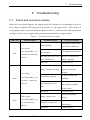
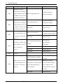
Troubleshooting .................................................................................................................. 63
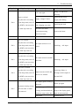
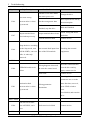
5.1 Faults and corrective actions .................................................................................... 63
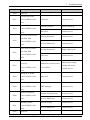
5.2 Alarm and treatment ................................................................................................ 68
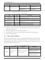
5.3 Other issues .............................................................................................................. 69
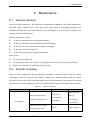
6
Maintenance........................................................................................................................ 71
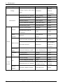
6.1 Routine maintain ...................................................................................................... 71
6.2 Periodic checking ..................................................................................................... 71
6.3 Parts replacement ..................................................................................................... 73
6.4 Drive storage ............................................................................................................ 73
6.5 Disposal ................................................................................................................... 73
Appendix .................................................................................................................................. 74
1
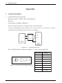
Communication........................................................................................................... 74
2
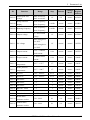
Parameter List ............................................................................................................. 83
Menu P01: Basic Parameter ...................................................................................... 83
Menu P02: Adjustive Parameter ................................................................................ 86
Menu P03: Accessorial Parameter ............................................................................. 87
Menu P04: Terminal Parameter ................................................................................. 89
Menu P05: Display Parameter................................................................................... 92
3
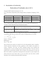
Declaration of Conformity .......................................................................................... 94
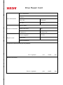
Drive Repair Card
.................................................................................................95
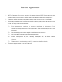
Service Agreement.................................................................................................................... 96
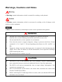
Warnings, Cautions and Notes
Warning
A Warning contains information, which is essential for avoiding a safety hazard.
Caution
A Caution contains information, which is necessary for avoiding a risk of damage to the
product or other equipment.
A Note contains information, which helps to ensure correct operation of the product.
WARNING
The HD710 AC drive should ONLY be installed by a qualified electrician.
Install the drive on the inflaming material like metal sheet in case a fire.
Do not install the Drive in the explosion air environment.
Even when the motor is stopped, dangerous voltage is present at the Power Circuit
terminals L1, L2, L3 and U, V, W and, depending on the frame size, DC+ and DC−, or
BR.
Dangerous voltage is present when input power is connected. After disconnecting the
supply, wait at least 10 minutes (to let the intermediate circuit capacitors discharge)
before removing the cover.
PE terminals must be earthed very well.
CAUTION
The HD710 is not a field repairable unit. Never attempt to repair a malfunctioning
unit; contact the factory or your local Authorized Service Center for replacement.
The HD710 will start up automatically after an input voltage interruption if the
external run command is on.
Prior to measurements on the motor or the motor cable, disconnect the motor cable
from the Variable Speed Drive.
Before connecting the Variable Speed Drive to mains, make sure that the HD710 front
and cable covers are closed.
1
1
1.1
Technical specification
Technical specification
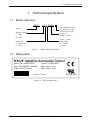
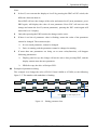
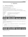
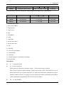
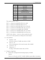
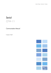
Model reference
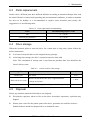
HD710 - 4 0 T 00550
Non: Standard G type
E: small size G type
P: small size P type
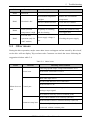
Power size
00040:0.4kW
|
01100:1.1kW
Input phase
D:1/3PH
T:3PH
Family
Supply voltage
2:220V
4:380V
Brake unit
0:Inner fitted
1:Non
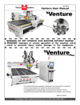
Figure1-1
1.2
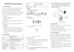
HD710 Model description
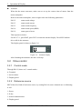
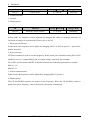
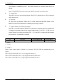
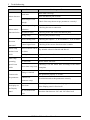
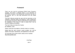
Rating label
Model: HD710-40T00150
Power: 1.5kW/2.8kVA
Input: 3PH 380VAC~480VAC
48Hz~62Hz 5.7A
Output: 3PH 0V~Input
0Hz~300Hz 4.2A
S . N. :
XXXXXXXXXX
Made in China
Figure1-2
E348255
HD710 Rating label
HD710 AC Drive User Manual
1
1
Technical specification
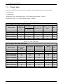
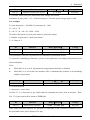
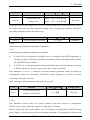
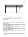
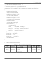
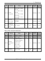
1.3
Power size
Power size of HD710 is referred to the standard 4 poles inductionmotor at rated voltage.
E: Heavy duty
P: Normal duty
Overload of E type and standard type: 150% rated output current, 1 minute
Overload of P type: 110% rated output current, 1 minute
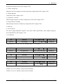
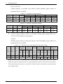
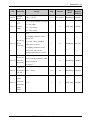
Table 1-1
220V rating data
Power supply: 220V, 50Hz, single/three phase
Drive
Power Size
(kVA)
Rated Input
Current (A)
HD710-20D00040
1.1
HD710-20D00075
HD710-20D00150
Rated Output
Current (A)
Motor Power
(kW)
Size
7.1/4
2.8
0.4
A
1.9
12.8/7.1
5
0.75
A
3.0
20.5/11.3
8
1.5
A
HD710-20D00220
4.2
24/14.5
11
2.2
B
HD710-20D00400
6.7
16.5
17.6
4
C
Model Name
1/3PH
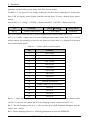
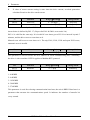
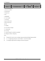
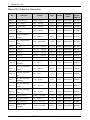
Table 1-2
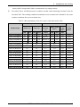
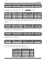
380V rating data
Power supply: 380V, 50Hz, three phase
2
Model Name
Drive
Power Size
(kVA)
Rated Input
Current (A)
Rated Output
Current (A)
Motor
Power (kW)
Size
HD710-40T00075
1.7
3.6
2.5
0.75
A
HD710-40T00150
2.8
5.7
4.2
1.5
A
HD710-40T00220E
3.4
6.1
5.2
2.2
A
HD710-40T00220
3.8
8.3
5.8
2.2
B
HD710-40T00400
6.3
13.2
9.5
3.7
B
HD710-40T00550E
8.6
14.3
13
5.5
B
HD710-40T00550P
8.6
14.3
13
5.5
B
HD710-40T00550
8.6
12.4
13
5.5
C
HD710-40T00750
11
16.1
17
7.5
C
HD710-40T01100P
15.2
21
23
11
C
HD710 AC Drive User Manual
1
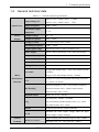
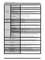
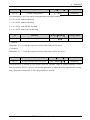
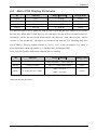
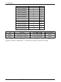
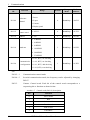
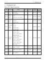
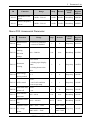
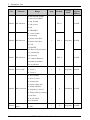
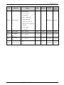
1.4
Technical specification
General technical data
Table 1-3
General technical specifications
Input Voltage Uin
Input Power
Input Frequency
Maximum Supply
200V(−10%)~240V(+10%)
1/3PH
380V(−10%)~480V(+10%)
3PH
48Hz~62Hz
≤3%
Imbalance
Power
Output Voltage
0V~Uin
Output
Output Frequency
0Hz~300Hz
Voltage Control
V/F, Open loop Vector Control
Switching Frequency
1kHz~15kHz
Adjust Speed range
Open loop vector -1:100, V/F mode -1:50
Start Torque
0.5Hz: 100% rated torque, 1Hz: 150% rated torque
Torque Accuracy
7%
Reference Resolution
Digit- 0.01Hz, Analogue- 0.1%×Max. frequency
Accel. & Decel. Rate
0.1s~3600s
Voltage Boost
0.1%~30.0% %
E type and standard type: 150% rated output current,
Overload
1 minute
Main
P type: 110% rated output current, 1 minute
Performance
Function
4 types: V/F (user can program) and ramp (2.0 power,
V/F
1.7 power, 1.2 power)
Injection frequency: 0.0%~20.0% Max. frequency
DC Braking
Injection current: 0.0%~300.0% rated current
Injection time: 0.0s~60.0s
Dynamic Brake
Brake rate: 0.0%~100.0%
Jog frequency: 0.00Hz~50.00Hz
Jog
Jog acceleration and deceleration rate: 0.1s~60.0s
Jog interval time: 0.1s~60.0s
Preset
4 speeds (decided by control terminals)
Maintain the rated output voltage when the input
AVR
power supply voltage changed.
Digit: Display panel, motorized pot (E-Pot), comms.
Control
Terminal
Reference Source
Analogue: AI1: 0V~10V, 0(4) mA~20mA
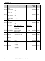
HD710 AC Drive User Manual
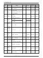
3
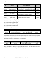
1
Technical specification
Operating Mode
With optional display panel, Control terminal, Serial
comms.
Digit Input Terminals
DI1~DI3: Programmable terminals
Digital Output
DO1: Programmable terminal, Max. output current:
Control
Terminals
50mA
Terminal
Analogue Output
AO1: programmable terminal, 0V~10V
1 programmable relay, contactor data:
AC250V/2A(COSφ =1)
Status Relay
AC250V/1A(COSφ =0.4)
DC30V/1A
Comms.
Connector
RJ-45 Port
Protocol
Modbus RTU
1000m rated
Altitude
1000m~3000m,1% rated current derating per 100m
Operating
-10C~+40C
Temperature
Max. Humidity
≤90%RH, no-condensing
Vibration
≤5.9m/s2(0.6g)
Storage Temperature
−40C~+70C
Environment
Indoor, non-flammable, no corrosive gasses, no
Running
contamination with electrically conductive material,
Environment
avoid dust which may restrict the fan
LED Display panel, HDOM-232, HDOM-USB,
Option Module
Display panel pallet, HDSOFT (PCTools), etc.
Output shortage, over current, over load, over
Protection
voltage, under Voltage, Phase loosing, over heat
(heatsink and junction), external trip, etc.
1.5kW and below: ≥89%
Efficiency
2.2kW~11kW:≥93%
Mounting Method
Enclosure
Cooling Method
4
Surface mounting, through hole
IP20, IP21 (by adding option device)
220V/0.4kW model is nature cool, others are forced
air cool
HD710 AC Drive User Manual
2
Installation and cabling
2 Installation and cabling
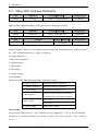
2.1
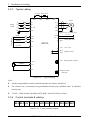
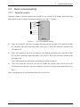
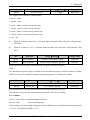
Dimension
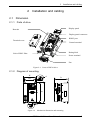
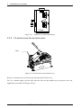
2.1.1 Parts of drive
Display panel
Barcode
Display panel connector
RS485 port
Terminal cover
Control terminal
Rating label
Link of EMC filter
Power terminal
Fan
Figure 2-1
Parts of HD710 drive
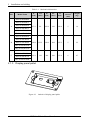
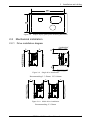
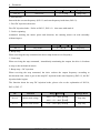
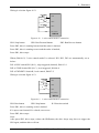
2.1.2 Diagram of mounting
W
W1
D
H
H1
Ø
Ø
Figure 2-2
Mechanical dimension and mounting
HD710 AC Drive User Manual
5
2
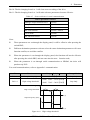
Installation and cabling
Table 2-1
Size
Model Name
Mechanical dimension
Mounting
Hole Ø
(mm)
Weight
(kg)
148.8
5
1.4
208
155.5
5
2.2
280
176.8
6
4.7
W
W1
H
H1
D
(mm)
(mm)
(mm)
(mm)
(mm)
97.4
80
202.4
190
142.4
123.5
220.4
163.1
142
300
HD710-20D00040
HD710-20D00075
A
HD710-20D00150
HD710-40T00075
HD710-40T00150
HD710-40T00220E
HD710-20D00220
HD710-40T00220
B
HD710-40T00400
HD710-40T00550E
HD710-40T00550P
HD710-20D00400
C
HD710-40T00550
HD710-40T00750
HD710-40T01100P
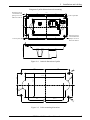
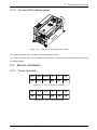
2.1.3 Display panel pallet
Figure 2-3
6
Outlook of display panel pallet
HD710 AC Drive User Manual
2
Installation and cabling
Diagram of pallet dimension and mounting
Mounting hole for
Countersunk head
phillips slot screw
145
66
67
Location pillar Ø 6
36
36
32
85
36
GB/T819.1M4*12
67
Mounting hole for
Countersunk head
phillips slot screw
GB/T819.1M4*12
66
54.5
3
Location pillar Ø 6
Figure 2-4
Outlook dimension of pallet
66
67
2-
7
R1
.7
36
32
74.7
36
R1
7.
36 5
113
∅7
52.5
.5
66
∅5
Figure 2-5
2-
46
67
Pallet mounting dimension
HD710 AC Drive User Manual
7
2
Installation and cabling
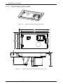
2.1.4 Simple display panel pallet
Figure 2-6
Figure 2-7
8
Outlook of Simple display panel pallet
Outlook dimension of simple display panel pallet
HD710 AC Drive User Manual
2
Figure 2-8
2.2
Installation and cabling
Simple display panel pallet mounting dimension
Mechanical installation
2.2.1 Drive installation diagram
L
L
H
H
Figure 2-9
Single drive installation
Recommending: L≥50mm,H≥100mm
L
L
L
Figure 2-10 Multi drives installation
Recommending: L≥50mm
HD710 AC Drive User Manual
9
2
Installation and cabling
Figure 2-11 Multi drives vertical installation
2.2.2 Fit and remove the terminal cover
Clips
Figure 2-12 fit and remove the terminal cover
Remove: twist the screw out, loose the clip then take off the cover.
Fit: by a suitable angle, put the clips into the slots on the middle cover, push the cover on,
tighten the screw M4×10 (Torque 1N·m).
10
HD710 AC Drive User Manual
2
Installation and cabling
2.2.3 On and off the display panel
Figure 2-13
Diagram of the display panel fitting
Off: push the spring clip, and then pull up the display panel.
On: fit the left two clips (correct angle) into the slots on the control pod, and then push down
the display panel.
2.3
Electric installation
2.3.1 Power terminals
L1
L2
L3/N
U
V
PE +DC +DC1 BR −DC
Figure 2-14
L1
L2
PE +DC
Figure 2-15
W
PE
Size A, B power terminals
L3
U
V
BR −DC
W
PE
Size C power terminals
HD710 AC Drive User Manual
11
2
Installation and cabling
Table 2-2
Power terminal of Size A, B, C
Terminals
Function
L1, L2, L3/N
AC power supply. For single phase supply, suggest to use L1, L3/N
+DC,+DC1
For DC choke, linked by busbar factory set
BR
Brake resistor, another end is +DC
−DC
Minus DC bus
U, V, W
Output terminals (Motor terminals)
PE
Protective earth terminal
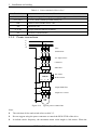
2.3.2 Power connections
L1
L2
L3
PE
Fuse
Switch/Gear
PE
AC input reactor
Contactor
PE
EMI filter
HD710
U V W
BR −DC
PE
+DC +DC1
L1 L2 L3/N
PE
Output EMI filter
PE
PE
Figure 2-16
DC choke
Brake resistor
Output AC reactor
M
Typical power connections
Note:
12
The selection of fuse and switch refers to table 2-3.
Do not suggest using the power contactor to control the RUN/STOP of the drive.
In default carrier frequency, the maximum motor cable length is 100 meters. When the
HD710 AC Drive User Manual
2
Installation and cabling
motor cable is longer than 100m, recommend to use output reactor.
For safety, Drive and Motor must be earthed, and the earth contacting resistance must be
less than 10Ω. The earthing conductor minimum cross-sectional area should be the same
as phase conductor the cross-sectional area.
Table 2-3 Recommending switch, fuse, power cable and control cable
Input
Model Name
Switch (A)
Power
Fuse (A)
1PH
3PH
1PH
HD710-20D00040
16
10
10
HD710-20D00075
25
25
16
HD710-20D00150
32
25
20
HD710-20D00220
50
32
32
3PH
Input
Current
(A)
Supply Cable
(mm2)
Motor
Cable
(mm2)
Control
Cable
(mm2)
1/3PH
1PH
3PH
3PH
6
7.1/4
1.0
1.0
1.0
≥0.5
16
12.8/7.1
1.5
1.0
1.0
≥0.5
16
20.5/11.3
2.5
1.5
1.0
≥0.5
20
24/14.5
4.0
2.5
1.5
≥0.5
HD710-20D00400
32
20
16.5
2.5
2.5
≥0.5
HD710-40T00075
10
6
3.6
1.0
1.0
≥0.5
HD710-40T00150
16
10
5.7
1.0
1.0
≥0.5
HD710-40T00220E
25
16
8.3
1.5
1.0
≥0.5
HD710-40T00220
25
16
8.3
1.5
1.0
≥0.5
HD710-40T00400
32
20
13.2
2.5
1.5
≥0.5
HD710-40T00550E
32
20
14.3
2.5
2.5
≥0.5
HD710-40T00550P
32
20
14.3
2.5
2.5
≥0.5
HD710-40T00550
25
16
12.4
2.5
2.5
≥0.5
HD710-40T00750
32
20
16.1
2.5
2.5
≥0.5
HD710-40T01100P
40
25
21
4.0
4.0
≥0.5
HD710 AC Drive User Manual
13
2
Installation and cabling
2.3.3 Typical cabling
DC choke Brake resistor
+DC1
+DC
BR
−DC
Motor
Supply
1/3 PH
L1
L1
L2
L2
V
L3
L3 /N
W
PE
PE
PE
FWD
U
AO1
DI1
M
Output frequency Analogue output
0V~10V
Programmable
0V
REV
DI2
Jog WD
DO1
Zero apeed +24V
24V
User +24V
DI3
HD710
Common
0V
RL1
RL2
CN3 Display panel connector
+10V
0V 10V
Healthy- closed
AI1
0V
RS485 terminal
RJ45 port
Figure 2-17
Typical cabling
Note:
All the programmable control terminal functions are factory default set.
For control wire, recommend using unshielded twisted pair, shielded cable, or shielded
twisted pair.
5.5kW~11kW models (including 220V/4kW), inner DC Choke is fitted.
2.3.4 Control terminals & cabling
RL1 RL2 0V AI1 10V AO1DO1 24V 0V DI1 DI2 DI3
Figure 2-18 Control terminal diagram
14
HD710 AC Drive User Manual
2
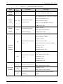
Table 2-4
Type
Terminal
Name
Installation and cabling
Control terminal & Comms. Port
Function
Tech. Spec.
Serial
RS485
RJ45 Port
Two lines, Modbus RTU protocol
Comms.
The common can be 0V or 24V by setting
the P04.10 (default is 0V)
Programmable digital
Digital
Input resistance: 10 kΩ
DI1~DI3
input terminals
Input
High, low logic threshold: 10V±1V
Sample time: 1ms
Output: 24V/0V
Programmable digital
Digital
DO1
Max. output current: 50mA
output terminal 1
output
Updating rate: 20ms
0V~10V
Input resistance: 100k
0(4)mA~20mA
Programmable Analogue
Load resistance:188
input 1
Min. potentiometer resistance: 0.5k
AI1
Analogue
Resolution: 0.1%
Input &
Accuracy: 2%
Output
Sampling period: 5ms
0V~10V
Max. output current: 5mA
Programmable Analogue
AO1
Resolution: 0.4%
output
Accuracy: ±5%
Updating rate: 5ms
Accuracy: 2%
10V
Analogue reference rail
Max. output current: 20mA
Accuracy: ±15%
Rail supply
24V
User supply
Max. output current: 100mA
& Relay
Common reference point for control
0V
Common
signal
HD710 AC Drive User Manual
15
2
Installation and cabling
Terminal
Name
Type
Function
Tech. Spec.
Type: form A (normal open)
Programmable Relay1
Updating rate: 5ms
output contactor
Contactor rating:
Rail supply
RL1, RL2
Default:
250VAC/2A(cosφ=1)
& Relay
Relay1 is closed when
250VAC/1A(cosφ=0.4)
powered and healthy.
30VDC/1A
Digital input common
There are three programmable digital input terminals.
The common of DI could be programmed as 0V or 24V, the default is 0V. The parameter
P04.10 can control the selection. When P04.10=0, common is 0V, P04.10=1, common is
24V.
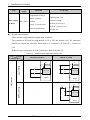
Different types connection of DI & Common as showed in table 2-5.
Table 2-5
P04.10
Connection
HD710 Digital input base function list
P04.10=0 (Source)
P04.10=1 (Sink)
+24V
24V
+24V
P04.10=0
By inner 24V
K1
K1
DI
DI
Inner circuit
Inner circuit
K2
K2
DI
DI
Switch type
0V
0V
HD710
HD710
+24V
DC
By outer supply
24V
P04.10=1
+24V
K1
DI
_
Inner circuit
K2
DI
0V
16
P04.10=1
24V
HD710 AC Drive User Manual
HD710
2
P04.10
Connection
P04.10=0 (Source)
Installation and cabling
P04.10=1 (Sink)
+24V
+24V
P04.10=0
24V
P04.10=1
By inner 24V
24V
K1
DI
DI
Inner circuit
Inner circuit
K2
DI
DI
0V
0V
OC (NPN)
HD710
HD710
DC
+24V
By Outer supply
+24V
24V
+24V
DC
P04. 10=0
24V
P04.10=1
+24V
DI
DI
Inner circuit
Inner circuit
DI
DI
0V
0V
HD710
HD710
+24V
+24V
P04 . 10=0
24V
P04.10=1
24V
By inner 24V
K1
DI
DI
Inner circuit
Inner circuit
K2
DI
DI
0V
OC (PNP)
0V
HD710
HD710
DC
+24V
+24V
By Outer supply
24V
P04.10=0
+24V
DC
24V
P 04. 10=1
+24V
DI
DI
Inner circuit
Inner circuit
DI
DI
0V
0V
HD710
HD710
Note: When outer supply is used, the range is 11V to 30V.
HD710 AC Drive User Manual
17
2
Installation and cabling
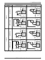
Digital output
There is 1 digital output terminal, OC type (24V output). When use the DO to drive the
rail winding, please take care the polarity of the rail winding of the relay, and use the
snubber circuit by the winding.
Inner
circuit
DO1
Diode
0V
HD710
Figure 2-19
Digital output connection
Analogue input
HD710 drive has one Analogue input channel.
+10V
0V 10V/ 0(4)mA 20mA
AI1
0V
HD710
Figure 2-20
Analogue input connection
Analogue output
Output is voltage (0V~10V), Max output current is 5mA.
AO1
Inner
circuit
Analogue
Meter
Output Range
0V 10V
0V
HD710
Figure 2-21
18
Analogue output
HD710 AC Drive User Manual
2
Installation and cabling
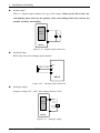
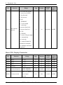
2.3.5 Brake resistor
The actual resistance on the site application is decided by the motor power, system inertia,
decelerating rate, etc. Users can choose it according to the actual situation.
Table 2-6
Spec.
Brake resistor draft rating
Min. resistance
(Ω)
Max. brake
current (A)
Peak power
(kW)
60s average
power (kW)
HD710-20D00040
41
10
4.15
1.9
HD710-20D00075
41
10
4.15
1.9
HD710-20D00150
41
10
4.15
1.9
HD710-40T00075
120
7
5.67
2.67
2.67
Model
HD710-40T00150
120
7
5.67
HD710-20D00220
20
21
8.48
4
HD710-40T00220E
120
7
5.67
2.67
HD710-40T00220
65
13
10.4
4.9
HD710-40T00400
50
17
13.5
6.4
HD710-20D00400
12
35
14.3
6.7
HD710-40T00550E
24
35
28.7
13.5
HD710-40T00550P
50
17
13.5
6.4
HD710-40T00550
24
35
28.7
13.5
HD710-40T00750
24
35
28.7
13.5
HD710-40T01100P
24
35
28.7
13.5
2.3.6 EMC guide
EMC management suggestion:
Immunity
360-degree ground clamps with the screen of the cable; avoid "Pigtail" ground fitting.
Control cable and power cable should be layout in the independent metal grooves; the
earth conductor in the motor cable must be connected directly to the earth terminal of the
drive and the motor. Recommend to use the shielded motor cable.
Cable clearance
Do not place control cable in a zone extending 300mm around the drive and power cables.
2.3.7 EMC filter
Optional RFI filter
Place the RFI filter close to the drive as possible, and the cable between the filter
and drive is shorter and better.
The enclosure of the filter must be connected with the drive earth terminal.
HD710 AC Drive User Manual
19
2
Installation and cabling
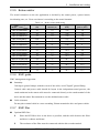
Inner EMC filter
The drive leakage current is different with the Inner EMC filter fitted or not.
Table 2-7
HD710 ground leakage current data
Size A
Model
200V
Size B
400V
200V
Size C
400V
200V
400V
With inner EMC filter (mA)
10
9
11
7
8.0
18.0
Without inner EMC filter (mA)
0. 1
0.1
0.2
0.1
0.0
0.3
Note:
The test condition of the Table 2-7 is no motor load.
When a ground leakage protecting contactor is used for front power supply, the
internal EMC filter should be removed.
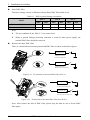
Remove the inner EMC filter
There is a metal link between the ground and EMC filter as show in the below figures.
Inner EMC filter
Tighten the screw up:
Fit the Inner EMC filter
Inner EMC filter
Untighten the screw:
Remove the Inner EMC filter
Figure 2-22
Fit and remove the inner EMC filter (Size A)
Inner EMC filter
Insert the link:
Connect the Inner EMC filter
Inner EMC filter
Pull out the link:
Disconnect the Inner EMC filter
Figure 2-23
Fit and remove the inner EMC filter (Size B & C)
Note: After remove the link of EMC filter, please keep the link in case to fit the EMC
filter again.
20
HD710 AC Drive User Manual
3
Operation & Display
3 Operation & Display
3.1
Display panel
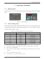
The HD710 drive can use two kinds of display panel: status display panel and LED display
panel.
Status display panel (built-in)
Figure 3-1
LED display panel (Optional module)
Operation panels
3.1.1 Status display panel
Status display panel is standard configuration of HD710 series drive. In some application, with
the default function parameters setting and status display panel, it is fit for requirement. Default
parameters setting as Table 3-1 shown:
Table 3-1 Terminal default function with status display panel
Input / Output Terminal
Function Code
Default
DI1
P04.05
0, run forward
DI2
P04.06
1, run reverse
DI3
P04.07
2, jog forward
AI1
P04.16
16, analogue reference frequency
AO1
P04.03
0, output frequency
DO1
P04.11
8, at zero speed
Relay1
P04.09
0, drive healthy
With status display panel, the following setting is necessary:
Rated power, voltage, current, frequency, and speed of motor and drive are matched;
Drive is in V/F control mode;
AI1 is selected as source reference, which inputs by external potentiometer and other
method;
Drive is under terminal control mode;
Acceleration rate is 5s and deceleration rate is 10s.
HD710 AC Drive User Manual
21
3
Operation & Display
With status display panel, only the following operation is enabling:
run forward (DI1), run reverse (DI2), jog forward (DI3) ;
Adjust setting frequency (AI1) with potentiometer;
Get output frequency with AO1;
Get drive Zero Speed Status with DO1;
Get drive status with Relay1.
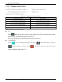
With indication of status display panel, the following information is valid:
Table 3-2
Status light
Status light display mode
Description
Off
Drive is powered off
Slow flashing
Drive stops, and the flashing period is about 1s.
Fast flashing
Drive is tripped, and the flashing period is about 200ms.
On
Drive is running
Change parameters setting with LED display panel or HDSoft, if it is required.
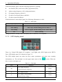
3.1.2 LED display panel
Figure 3-2
LED display panel
There is a 5-digit LED display of 8 segment, 3 unit lights, and a RUN light on the HD710
Drive LED display panel. It is showed as figure 3-2.
The LED display panel can show the drive status, parameters and value, trip, warning
information, etc. The run light is on the upper right corner of the
switch. When the
drive is active, the light is on.
Table 3-3
Unit
Unit light
Function
Colour
On: output frequency
Hz
Green
Flash: Reference frequency
A
On: Output current
Green
On: Output voltage (RMS)
V
Green
Flash: DC bus voltage
22
HD710 AC Drive User Manual
3
Operation & Display
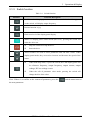
3.1.3 Switch function
Table 3-4
Switches
Switch function
Function Description
In different level display, press the switch will return the last level. Long press
on the switch, will display output frequency.
Default function is jog.
Enter next level of the display panel display.
When it is display panel control mode (P01.03=2), pressing the switch will
make the drive run.
Stop, the switch will stop the drive.
Reset the drive.
These switches are used to select parameters and edit their values. Under
display panel mode, they are used to increase and decrease the speed of the
motor.
Under Run/Stop mode, if press the switch, the LED display panel will
be reference frequency, output frequency, output current, output
voltage, DC bus voltage in turn.
Under the edit of parameter value mode, pressing the switch will
change the bite of the value.
Note: If there is a conflict on the content of parameter, press the
switch cannot enter to
the next parameter.
HD710 AC Drive User Manual
23
3
Operation & Display
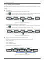
3.1.4 Display panel operation
The display panel can control the running of the drive, or monitor the status of the drive, details
as below:
LED display
LED default shows the output frequency when the drive stops.
Press
will cycle display: reference frequency, output frequency, output current,
output voltage, DC bus voltage. Operation procedure is as figure 3-3A:
Reference frequency
Output frequency
0.00
Output current
Output voltage
DC bus voltage
0.0
0
537
0.00
Figure 3-3A Display switchover flow
In running mode, normal display is output frequency.
Press
will cycle display: output frequency, reference frequency, output current,
output voltage, DC bus voltage. Operation procedure is as figure 3-3B:
Output frequency Reference frequency
0.00
0.00
Output voltage
0.0
Figure 3-3B
Output current
DC bus voltage
0
537
Display switchover flow
The view of the parameter and the edit of parameter value
For HD710 family, there are three levels about parameter view and edit.
Level1: menu group
Level2: parameter
Level3: parameter content
Operation flow is described in figure 3-4:
Change menu group
0.00
P01
Change parameter
Change parameter value
P01.01
Figure 3-4
24
0
Left shift parameters
Default display
Parameter view and edit flow
HD710 AC Drive User Manual
P01.02
3
Operation & Display
Note:
In level3, user can turn the display to level2 by pressing the PRG or ESC switch, the
difference between them is:
Press PRG will save the change of the value and return level2 (next parameter), press
PRG again, will display the value of next parameter. Press ESC will not save the
change and return the level2 (current parameter), pressing the ESC switch again will
return the level 1 display.
Only after pressing the PRG switch, the change can be active.
If there is no bite of parameter value is flashing, means the value of the parameter
cannot be changed. The reasons maybe:
It is an actual parameter, cannot be changed.
Drive is running, and the parameter cannot be changed at running.
If more than one parameters are being set to same value(function), will happen
following phenomena:
Display panel set up, the change will not be active after pressing PRG, and the
display cannot enter the next parameter.
HDSoft set up, the drive will trip at F021.
Example of parameter editing
The example is to change the value of P02.01 from 0.00Hz to 45.50Hz, as the following
figure 3-5. The number with underline is flashing.
0.00
P01
P02
1 time
0.00
P02.01
1 time
1 time
0.50
0.00
1 time
5 time
1 time
0.00
P02
P02.02
45.50
5.50
4 time
Press
Figure 3-5
0.50
5.50
1 time
5 time
key, until display 45.50
Editing parameter flow
HD710 AC Drive User Manual
25
3
Operation & Display
Autotune
When do the motor auto-tune, make sure to set up the correct data of motor from the
motor nameplate.
Refer to the motor nameplate; enter in right value into following parameters:
P01.12
motor rated voltage
P01.13
motor rated current
P01.15
motor rated frequency
P01.16
motor rated speed (RPM)
P01.19
motor power factor
Then operate as below:
Set P01.17=1, press PRG, press ESC to return the normal display. Press RUN and the
drive will do the autotune.
The display panel is shown as figure 3-6:
Figure 3-6
Autotune display
After finishing the autotune, the drive will stop.
3.2
Drive control
3.2.1 Control mode
Through P01.03, there are 3 control modes:
0: Terminal
1: Serial comms.
2: Display panel
3.2.2 Reference source
HD710 has five kinds of reference source, by setting P01.04, source channels are as following:
0: AI1
1: Preset
2: E-Pot
3: Serial communication
4: Display panel
26
HD710 AC Drive User Manual
3
3.3
Operation & Display
Quick commissioning
3.3.1 Terminal control
Terminal control is default control mode of HD710. As a result, LED display panel RUN and
MF (default is jog) is invalid. Terminal connection is as Fig. 3-7 shown:
K1
K2
K3
DI1
DI2
DI3
0V/24V
10V
AI1
0V
HD710
Figure 3-7
Two-wire (default) cabling
Close the switch K1, the drive is running forward and the run light is on. Open the switch
K1, the drive will stop at the ramp mode set by P01.11. When the inverter is disabled, the
run light is off.
Close the switch K2, the drive is running reverse and the run light is on. Open the switch
K2, the drive will stop at the ramp mode set by P01.11. When the inverter is disabled, the
run light is off.
Note: Adjusting the potentiometer can change the output frequency.
Close the switch K3, the drive will run at 5.00Hz (the default value of P02.18) at the
acceleration rate (P01.08). Open the switch K3, the drive will stop at the ramp mode set by
P01.11.
Note: Jog again have to wait the interval period set by P02.19.
HD710 AC Drive User Manual
27
3
Operation & Display
3.3.2 Display panel control
Set: P01.03 (The user operation mode) =2
P01.04 (Frequency source selector) =4
display panel control mode
display panel
Other parameters Settings as table 3-5:
Table 3-5
Display panel control setup
Parameter Setup
Description
P01.13=motor nameplate data
Set the motor rated voltage
P01.14=motor nameplate data
Set the motor rated current
P01.15=motor nameplate data
Set the motor rated frequency
P01.16=motor nameplate data
Set the motor rated speed
P01.19=motor nameplate data
Set the Power factor of the motor
Other parameters are default setup.
Jog
Press
and hold, the drive will run at the setting value of P02.18. Release the switch,
the drive will stop at the ramp mode set by P01.11.
Note: Jog again have to wait the interval period set by P02.19.
Common Run
Press
, drive is running, Run light is on. Press
, output frequency is down. Press
, the drive will stop, when the inverter
output is disabled, Run light is off.
28
, output frequency is up, Press
HD710 AC Drive User Manual
4
Parameter
4 Parameter
4.1
Property of parameter
The following parameter description includes:
Parameter ID: code of parameter.
Parameter name: simple explanation of the parameter.
Parameter range: the range of the parameter’s content, in 【 】is the default value.
Change mode: to define if the parameter can be modified, and under what condition can change
the parameter.
Run&Stop
Write & Read can be done at running and stopping.
Stop Only
Write & Read can be done only at stopping.
Actual
Read only
4.2
Menu P01: Basic Parameter
ID
Function
Range【Default】
Change Mode
P01.01
Load default
0~1【0】
Stop Only
0: no action
1: load default
When drive is not in running state, load default value (except for motor’s parameters) and
cloning them to EEPROM if P01.01=1.
Note:
Copy drive parameters to display panel with P03.03 = 1, before restoring factory
parameter;
Restore factory parameter can also be executed in fault status.
ID
Function
Range【Default】
Change Mode
P01.02
Motor control mode
0~1【0】
Stop Only
0: V/F
1: Open loop vector control
HD710 AC Drive User Manual
29
4
Parameter
ID
Function
Range【Default】
Change Mode
P01.03
Control mode
0~2【0】
Stop Only
0: Control terminal
1: Comms.
2: Display panel
ID
Function
Range【Default】
Change Mode
P01.04
Reference source selector
0~4【0】
Run&Stop
0: Analogue reference
In this mode, the frequency can be adjusted by changing the value of Analogue reference. It
can work in voltage or current mode. Please refer to P01.05.
1: Preset speed reference
In this mode, the frequency can be adjust by changing P02.07 to P02.10 (preset 1~prest4).See
menu2 for detail.
2: E-pot reference
UP/Down terminal is used to set the frequency. In this mode, two terminals among DI1 to DI3
should be set to 11 (output falling) and 10 (output rising) separately. For example:
To set DI1 as UP terminal and DI2 as DOWN terminal, the following operations are needed.
P04.05 = 10
P04.06 = 11
3: Serial communication
In this mode, the frequency can be adjusted by changing P02.07 (preset 1)
4: Display panel
The UP and DOWN switches are used to set the frequency. When the UP (DOWN) switch is
pushed, the given frequency value will increase (decrease) continuously.
30
HD710 AC Drive User Manual
4
Parameter
ID
Function
Range【Default】
Change Mode
P01.05
AI mode selector
0~6【6】
Stop Only
AI1 signal can be voltage or current mode:
0: 0mA~20mA
1: 20mA~0mA
2: 4mA~20mA (current loosing with trip)
3: 20mA~4mA (current loosing with trip)
4: 4mA~20mA (current loosing without trip)
5: 20mA~4mA (current loosing without trip)
6: 0V~10V
When it is setup as from 0 to 5, if current input is beyond 26mA, the drive will generate a
trip F012.
When it is setup as 2 or 3, if current input less than 3mA, the drive will generate a trip
F013.
Range【Default】
Change Mode
P01.06
ID
Max. frequency
Function
0.00Hz~300.00Hz【50.00】
Stop Only
P01.07
Min. frequency
0.00Hz~Max. frequency【0.00】
Stop Only
These parameters are used to select the Max. frequency and Min. frequency.
Note:
The minimum frequency range is 0.00Hz to the maximum frequency, and the default is 0.00Hz.
If P03.01=0 (reverse enabled), then the minimum frequency is constant for 0.00Hz.
ID
Function
Range【Default】
Change Mode
P01.08
P01.09
Accel. rate
0.0s~3600.0s【5.0】
Run&Stop
Decel. rate
0.0s~3600.0s【10.0】
Run&Stop
Acceleration rate is the time from 0.00Hz to maximum reference (P01.06).
Deceleration rate is the time from maximum reference (P01.06) to 0.00Hz.
For example:
P01.06 =100.00Hz, set up the maximum reference
P01.08=10.0s
set accelerating time
After starting, the drive output frequency is from 0.00Hz ramp to 50.00Hz the accelerating time
is: 10.0s ×(50.00Hz/100.00Hz) = 5.0s
HD710 AC Drive User Manual
31
4
Parameter
ID
Function
Range【Default】
Change Mode
P01.10
Start mode
0~2【0】
Stop Only
0: Start directly
Start with the set start frequency (P02.11) and start frequency hold time (P02.12).
1: First DC injection, then start
First DC injection brake(Refer to P02.13, P02.14),then start with mode 0.
3: Catch a spinning
Automatic tracking the motor speed and direction, the running motor can start smoothly
without impact.
ID
Function
Range【Default】
Change Mode
P01.11
Stop mode
0~2【0】
Stop Only
0: Ramp stop
When receiving the stop command, the drive ramp down to zero frequency.
1: Coast stop
When receiving the stop command, immediately terminating the output, the drive is freedom
to stop as the mechanical inertia.
3: Ramp stop + DC injection
When receiving the stop command, the drive reduces the output frequency according to
deceleration time, when it gets to the stop DC injection brake start frequency (P02.15), the DC
injection brake begins.
The function about the stop DC injection brake, please refer to the explanation of P02.16,
P02.16, P02.17.
ID
Function
Range【Default】
P01.12
Motor rated voltage
Change Mode
200V:0V~240V【220】
Stop Only
400V:0V~480V【380】
P01.13
32
Motor rated current
0.1A~30.0A【by model】
HD710 AC Drive User Manual
Stop Only
4
Parameter
ID
Function
Range【Default】
Change Mode
P01.14
Number of motor pairs of pole
0~4【0】
Stop Only
0: Calculate motor pole pairs with motor rated voltage and current
P(Number of pole pairs) = 60 × F(rated frequency) / N(rated speed). Integer part is valid.
For example:
F (rated frequency) = 50.00Hz, N (rated speed) = 1460.
N = 60 * F / P
P = 60 * F / N = 60 * 50 / 1460 = 2.054
Therefore, the motor is 2-pole pairs motor (4-pole pairs motor).
1: Number of pole pairs (2 pole pairs motor)
2~4: Same as 1.
ID
Function
Range【Default】
Change
P01.15
Motor rated frequency
1.00Hz~300.0Hz【50】
Stop
Only
Mode
P01.16
Motor full load speed
0rpm~18000rpm【0】
Stop Only
This parameter is used to set parameters of controlled asynchronous motor.
To ensure the controlling performance, please set the parameters according to the parameters of
motor nameplate.
Note:
When P01.16 is set to 0, slip automatic compensation function is disabled.
When P01.16 is set to non-zero numbers, P01.14 automatically switches to 0 calculating
number of pole-pairs.
ID
Function
Range【Default】
Change
P01.17
Auto-tune
0~1【0】
Stop
Only
Mode
0: No measurement
1: Auto-tune 1 (run a time)
Set P01.17=1, at first time to get enable and run command, the drive start to measure. Then,
P01.17=0, the result will be stored to EEPROM.
ID
Function
Range【Default】
Change
P01.18
Motor stator resistance
0.000Ω~60.000Ω【0】
Stop
Only
Mode
After motor auto-tune finished, the parameter is refreshed. If the calculated resistance is over
the maximum value, drive display F016 trip.
HD710 AC Drive User Manual
33
4
Parameter
ID
Function
Range【Default】
Change
P01.19
Motor power factor
0.00~1.00【0.85】
Stop
Only
Mode
This parameter and motor rated current (P01.13) are used to calculate the motor rated torques
current and excited current.
The motor rated torques current is used to control by drive, while the excited current is used to
compensate the stator resistance in vector controlling mode.
ID
Function
P01.20
Switch frequency
Range【Default】
Change Mode
1kHz~15kHz【by model】
Run&Stop
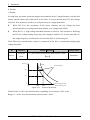
This parameter is used to set the carrier frequency of PWM output from drive. Carrier
frequency affects noise and loss of motors. Please refer the table following:
Table 4-1
The carrier frequency changes on the influence of motors and drives
Carrier frequency
Lower → higher
Motor noise
More → less
Waveform of current
Worse → better
Motor temperature
Higher → lower
Drive temperature
Lower → higher
Leakage current
Less → more
Radiation
Less → more
ID
Function
Range【Default】
Change Mode
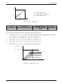
P01.21
Voltage boost
0.0%~30.0%【by model】
Run&Stop
Voltage boost is used to improve the torque ability at low frequency. The higher voltage boost,
the easier motor becomes hot and over current. For big load, increasing the value; while
decrease the value. When the value is set to 0, there is no torque improvement.
Voltage boost (P01.21) for each drive power, as following table shows:
Table 4-2
34
Voltage boost default value of each drive power
Drive Power
Default Value
0.4kW~4kW
3.0%
5.5kW~11kW
2.0%
HD710 AC Drive User Manual
4
Parameter
Ve
Ve:Motor rated voltage
Vb:Boost voltage=Ve×P01.21
fb:Motor rated frequency
Vb
fb/2
fb
Figure 4-1
Voltage boost
ID
Function
Range【Default】
Change
P01.22
V/F control mode
0~3【0】
Stop
Only
Mode
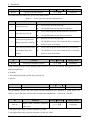
Different V/F characteristic is defined by P00.23 to meet the demanding from different load.
There are three kinds of fixed curve and one user programmed line.
When P01.22 is 0, user can define the different fold lines by setting of P02.01~P02.02.
The default V/F is a straight line, as the line 0 in Figure 4-2.
When P01.22 is 1, it is a 2.0 law ramp, curve1 in figure 4-2.
When P01.22 is 2, it is a 1.7 law ramp, curve2 in figure 4-2.
When P01.22 is 3, it is a 1.2 law ramp, curve3 in figure 4-2.
Output voltage (V)
Motor rated voltage
0
3
2
1
Motor rated frequency
Figure 4-2
Output frequency (Hz)
Motor V/F curve
HD710 AC Drive User Manual
35
4
Parameter
ID
Function
Range【Default】
Change Mode
P01.23
Power up E-Pot reference
0~3【0】
Stop Only
The motorized pot modes are given in the table below:
Table 4-3
P01.23
0
Power up E-Pot reference default value
Mode
Comment
Zero at power up
1
Last value at power up
Zero at power-up and only
2
change when drive running
Last value at power-up and
3
only change when drive
running
Reset to zero at each power-up.
UP, DOWN and reset are active at all times.
Set to value at power-down when drive power-up.
UP, DOWN and reset are active at all times.
Reset to zero at each power-up.
UP, DOWN are only active when the drive is running.
Reset is active at all times.
Set to value at power-down when drive powered-up.
UP, DOWN are only active when the drive is running.
Reset is active at all times.
ID
Function
Range【Default】
Change Mode
P01.24
Power up reference frequency
0~2【0】
Run&Stop
When reference source is the display panel reference (P01.04=4), after the drive power up, the
output frequency is:
0: 0.00Hz
1: the running frequency when last powered off
2: preset1
ID
Function
Range【Default】
Change Mode
P01.25
UP/DOWN Acceleration rate
0.0s~250.0s【10】
Run&Stop
This parameter defines the time taken for the motorized pot function to ramp from 0 to
100.0%. Twice this time will be taken to adjust the output from −100.0% to +100.0%.
ID
Function
Range【Default】
Change Mode
0~1【1】
Stop Only
Digital mode, reference frequency
P01.26
when rerun
0: run again after stop, reference frequency is 0Hz.
1: run again after stop, reference frequency is the last value.
36
HD710 AC Drive User Manual
4
4.3
Parameter
Menu P02: Adjustive Parameter
ID
Function
Range【Default】
Change Mode
P02.01
V/F frequency
0.00Hz~P01.15【0.00】
Stop Only
P02.02
V/F voltage
0.0%~100.0%【0.0】
Stop Only
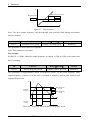
When P01.22=0, user can set up the parameters P02.01 and P02.02 to define the V/F curve, as
the below diagram. By adding a point on the V/F curve showed as below, this can improve the
performance during the acceleration under a specific application situation. Under the default
setup, the V/F curve is a straight line.
Voltage (%)
100%
V
f
Figure 4-3
fb Output frequency (Hz)
V point of V/F
ID
Function
Range【Default】
Change Mode
P02.03
Current limit
0%~300%【200】
Stop Only
This parameter is a coefficient for current limit. It is efficient for both motor and generator
torques. When P02.03 is 100%, the limited current is equal to motor rated current.
Range【Default】
Change Mode
P02.04
ID
Current controller Kp gain
Function
0.001~10.000【0.020】
Stop Only
P02.05
Current controller Ki time
0.00s~100.00s【0.20】
Stop Only
User can adjust dynamic responding characteristic of system by setting P02.04 and P02.05. It
can shorten time of dynamic responding to increase proportion gain or decrease integral time.
However, adjusting too more will cause system shocking.
Our suggestion: if default setting cannot meet requisition, please make sharp tuning with it:
increase value of P02.04 at first to ensure that system does not shock, and then decrease
P02.05 to speedup respond.
HD710 AC Drive User Manual
37
4
Parameter
ID
Function
Range【Default】
Change Mode
P02.06
Slip compensation error
0rpm~18000rpm【0】
Stop Only
The changing of motor load torque will generate error of motor slipping, and variety of motor
speed. When motor speed does not match to references, adjusting P02.06 will fix it.
ID
Function
Range【Default】
Change Mode
P02.07
Preset 1
−P01.06~+P01.06【5.00】
Stop Only
P02.08
Preset 2
−P01.06~+P01.06【10.00】
Stop Only
P02.09
Preset 3
−P01.06~+P01.06【20.00】
Stop Only
P02.10
Preset 4
−P01.06~+P01.06【30.00】
Stop Only
With input terminal selection mode, one of preset1 (P02.07)~preset4 (P02.10) acts as setting
frequency.
Note: Preset reference is prior to other mode.
For example:
Setting parameters as following:
P04.06 = 8
DI2 acts as preset select bit0
P04.07 = 9
DI3 acts as preset select bit1
As a result, preset has the following two operation modes:
When preset is selected as reference, the relationship between selected preset and
terminal status is as Table 4-4 shown.
Table 4-4
DI3 status (1 bit)
DI2 status (0 bit)
Frequency source selector
OFF
OFF
Preset 1 (P02.07)
OFF
ON
Preset 2 (P02.08)
ON
OFF
Preset 3 (P02.09)
ON
ON
Preset 4 (P02.10)
When preset is not set as reference, the relationship is as Table 4-5 shown.
Table 4-5
38
Map1 between preset and preset select terminal
Map2 between preset and preset select terminal
DI3 status (1 bit)
DI2 status (0 bit)
Frequency source selector
OFF
OFF
Keep initial setting reference
OFF
ON
Preset 2 (P02.08)
ON
OFF
Preset 3 (P02.09)
ON
ON
Preset 4 (P02.10)
HD710 AC Drive User Manual
4
Parameter
ID
Function
Range【Default】
Change Mode
P02.11
Start frequency
0.00Hz~50.00Hz【0.00】
Stop Only
P02.12
Hold time for start frequency
0.0s~60.0s【0.0】
Stop Only
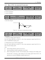
Start frequency (fs, P02.11) means the initiate speed at drive startup. Hold time for start
frequency (T1, P02.12) is the holding time at Fs. Refer to the below diagram:
Output frequency
(Hz)
fmax
fs
t1
Figure 4-4
Time (s)
Start frequency & Hold time for start frequency
ID
Function
Range【Default】
Change Mode
P02.13
Start DC injection current
0.0%~100.0%【0.0】
Run&Stop
P02.14
Start DC injection time
0.0s~60.0s【0.0】
Run&Stop
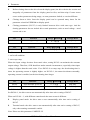
The parameters P02.13 & P02.14 are valid at P01.10=1 only. Refer to the below diagram.
Start DC injection current (P02.13) is present of drive rated current. If start DC injection time
(P02.14) is 0.0s, there is no process of DC injection.
Output frequency (Hz)
Time (s)
Output Voltage (V)
(Effective value)
DC injection current
(P02.13)
DC injection time
(P02.14)
Time (s)
Run command
Figure 4-5
DC injection
HD710 AC Drive User Manual
39
4
Parameter
ID
Function
Range【Default】
Change Mode
P02.15
Stop DC injecting frequency
0.0%~20.0%【0.0】
Run&Stop
P02.16
Stop DC injecting current
0.0%~100.0%【0.0】
Run&Stop
P02.17
Stop DC injecting time
0.00s~60.00s【0.00】
Run&Stop
P02.15 is certain percent of P01.06.
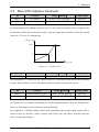
P02.16 is certain percent of P01.13.
If Stop DC injection time is 0.00s, the drive will not DC inject.
ID
Function
Range【Default】
Change
P02.18
Jog frequency
0.00Hz~50.00Hz【0.00】
Run&Stop
Mode
P02.19
Jog interval time
0.1s~60.0s【1.0】
Run&Stop
Output frequency
(Hz)
Jog accelerating
time
Jog decelerating
time
f
Time (s)
Jog command
Jog interval time
Figure 4-6
jog
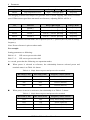
Jog interval time (P02.19) is from cancelling the last Jog command to the next Jog command
coming into effect. The Jog command is invalid during Jog interval time and the drive will run
at 0.0Hz. If the command is always valid, it will carry out the Jog command after finished the
Jog interval time.
Note:
Under display panel control mode, press the switch MF will enable Jog command with
default setting. After releasing the switch MF, drive will stop according to setting of
P01.11. In Terminal Control mode, some of DI terminals can be programmed to realize
Jog forward or Jog reverse function. So does Serial Communication.
Jog accelerating/decelerating rate is according to Acc/Dec time (P01.08/P01.09).
Jog command is NOT valid in running state.
Running command is invalid during jogging.
40
HD710 AC Drive User Manual
4
Output frequency
(Hz)
Parameter
f
Jog frequency
Time (s)
Run command
Jog command
ID
Function
Range【Default】
Change Mode
P02.20
Skip frequency
0.00Hz~P01.06【0.00】
Stop Only
P02.21
Band of skip frequency
0.00Hz~30.00Hz【0.00】
Stop Only
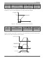
The skip frequency is available to prevent continuous operation at a speed that would cause
mechanical resonance. When a skip reference parameter is set to 0, filter is disabled. The skip
reference band parameters define the frequency or speed range either side of the programmed
skip reference, over which reference are rejected. The actual reject band is therefore twice that
programmed in these parameters, the skip reference parameters defining the centre of the band.
When the selected reference is within a band, the lower limit value of the band is the last
reference. The last reference is limited among minimum frequency (P01.07) to maximum
frequency (P01.06).
For example:
P01.06=50.00Hz, P01.07=0.00Hz,
P02.20=2.00Hz, P02.21=1.00Hz. (Other parameters with default)
When the given frequency is among 1.00Hz to 3.00Hz, the last frequency is 1.00Hz. When the
given frequency is among 4.00Hz to 6.00Hz, the last frequency is 4.00Hz. The frequency out
of skip reference band is not changed.
For example:
P01.06=50.00Hz, P01.07=0.10Hz,
P02.20=2.00Hz, P02.21=3.00Hz. (Other parameters with default)
When the given frequency is among 0.00Hz to5.00Hz, the last frequency is 0.10Hz. The
frequency out of skip reference band is not changed.
HD710 AC Drive User Manual
41
4
Parameter
f
Band of skip frequency
Skip frequency
P02.21
P02.20
P02.21
t
Figure 4-7
Skip frequency
Note: The drive output frequency can pass through skip reference band during acceleration
and deceleration.
ID
Function
Range【Default】
Change Mode
P02.22
Threshold of zero speed
0.00Hz~P01.06【0.50】
Run&Stop
This parameter is used with P02.23 together.
Note: This parameter is no polar.
For example:
Set P02.22 = 0.50Hz, when the output frequency is ranged −0.5Hz to 0.5Hz, at the same time
drive is running.
ID
Function
Range【Default】
Change
P02.23
Band of frequency arrival
0.00Hz~P01.06【2.50】
Run&Stop
Mode
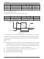
This parameter is supplementary define of frequency arrival. As the below diagram, when
output frequency of device is in the error, if defined to frequency arrived, DO terminal will
output different level.
f
P02.23
Band of frequency
arrival
P02.23
Band of frequency
arrival
Reference
Frequency
t
Frequency
Arrival
Figure 4-8
42
Frequency arrival & Band of frequency arrival
HD710 AC Drive User Manual
4
4.4
Parameter
Menu P03: Accessorial Parameter
ID
Function
Range【Default】
Change Mode
P03.01
Run direction select
0~1【0】
Stop Only
This parameter is used to permit drive reversing or not.
0: reverse is permitted
1: reverse is disabled
ID
Function
Range【Default】
Change Mode
P03.02
Deadtime for running direction change
0.0s~3000.0s【0.0】
Run&Stop
When drive changes run direction, it will hold at 0.00Hz for some time, which is set by P03.02.
As the below diagram.
Output frequency (Hz)
Time (s)
t1
Figure 4-9
Dead time for running direction change
ID
Function
Range【Default】
Change Mode
P03.03
Parameter cloning
0~2【0】
Stop Only
0: No action
1: Cloning up to display panel from drive
Press the switch MOD after set P03.03=1, drive clones parameters ranged from P01.01 to
P05.25 to EEPROM on display panel.
2: Cloning down to drive from the display panel
Press the switch MOD after set P03.03=2, drive clones parameters ranged from P01.01 to
P05.25 from the display panel.
Note:
After cloning parameters, P03.03 recovers to 0.
Only the parameters with US attribution can be cloned.
Before cloning down to the drive from the display panel, cloning up to the display panel
from the drive is necessary. After cloning up to the display panel from the drive, the
parameters are stored in EEPROM on display panel forever.
HD710 AC Drive User Manual
43
4
Parameter
Before cloning down to the drive from the display panel, the drive checks the version and
integrality of parameters from the display panel at first, and then trips if some errors
occur such as parameters being empty, or some parameter lacked, or version different.
Cloning down to drive from the display panel can be operated many times for the
parameter existed in EEPROM on display panel.
Cloning parameters (P05.23) is only limited between drive with same type. And the
cloning parameters do not include drive rated parameters, such as rated voltage、rated
current and so on.
ID
Function
Range【Default】
Change Mode
P03.04
Auto energy saving control
0~1【0】
Stop Only
ID
Function
Range【Default】
Change Mode
P03.05
AVR control
0~2【1】
Stop Only
0: off
1: on for all condition
2: on except ramp
When the input voltage deviates from rated value, setting P03.05 can maintain the constant
output voltage. Therefore, AVR should act under normal circumstances, especially when input
voltage is higher than the rated value. If set P03.05=0 at ramp stop, the decelerating time is
short, the operating current is slightly higher; set P03.05=1, the motor decelerates smoothly,
operating current is smaller, but the decelerating time longer.
ID
Function
Range【Default】
Change Mode
P03.06
Auto-start after power off
0~1【0】
Stop Only
P03.07
Wait time for auto-start
0.0s~60.0s【0.0】
Run&Stop
Set P03.06=0, the drive cannot run automatically.
Set P03.06=1, the drive start to run automatically after time arrive setting of P03.07.
When set P03.06 = 1, with different control mode the auto-restart is different:
Display panel mode: the drive start to run automatically after time arrive setting of
P03.07
Terminal mode: the drive start to run automatically after time arrive setting of P03.07,
only when running command is enable.
Note: Please use this parameter CAREFULLY.
44
HD710 AC Drive User Manual
4
Parameter
ID
Function
Range【Default】
Change
P03.08
Dynamic brake rate
0.0%~100.0%【50.0】
Run&Stop
Mode
Dynamic brake DC
200V:350V~390V【390】
voltage points
400V:650V~780V【780】
P03.09
Stop Only
Brake unit works in the chopper way. P03.08 is used to define duty ratio of brake unit switch,
the higher duty ratio the more apparent braking effect. Setting this parameter should be
according to braking resistor value and power.
ID
Function
Range【Default】
Change
P03.10
Switch frequency auto adjust
0~1【1】
Run&Stop
Mode
0: Off
Switch frequency automatic adjustment is disabled.
1: On
Switch frequency automatic adjustment is enabled.
If set P03.10=0, this function is disabled. Once it is disabled, if the IGBT temperature is
too high, the drive will produce trip F009 immediately, LED on the display panel will be
off, and IGBT will be blocked.
If set P03.10=1, thermal protection will automatically adjust switch frequency according
to IGBT temperature, in order to prevent the drive from overheating.
This parameter is set to 1, frequency converter thermal protection model according to
automatically adjust the temperature will IGBT switch frequency, in order to prevent
overheating frequency converter.
Note: Automatic adjustment range limited to P01.20 value.
ID
Function
Range【Default】
Change Mode
0~1【0】
Stop Only
Low DC bus operation
P03.11
(only for 380V models)
0: Off
1: On
This function is used to allow the 3-phase 380VAC input drive can run in single-phase
220VAC power source when the 3-phase AC input power is failure.
When 3-phase 380 VAC power failure, user can switch it to single-phase 220VAC backup
power supply, so the drive can still run at derating conditions. For example, the function can
HD710 AC Drive User Manual
45
4
Parameter
guarantee elevator safety to stop at the door after a power failure.
Set P03.11=1, the drive DC bus voltage reduction will cause lower output power. At the same
time, LED on display panel flashing indicates that the drive is using a backup lower power
supply.
Note:If P03.11=1, voltage: <330VDC→display trip H005, <230VDC→display trip F003.
ID
Function
Range【Default】
Change Mode
P03.12
Comms. control word
0~65535【0】
Run&Stop
P03.12 is used to control the drive in serial communication control mode (P01.03=1).
P03.12 is Comms. control word in serial communication control mode. P03.12 is a 16-bit
binary number. the meanings of each bit are shown as below table. It is displayed in decimal
form on the display panel.
Table 4-6
Comms. control word description
Bit
Function
0
Drive enable
1
Run
2
3-wire enable
3
Run forward
4
Run reverse
5
FWD/REV
6
Jog forward
7
Jog reverse
8
Fault reset
9
Saving parameters
10
Clean the trip tack log
11
Enable comms to write parameters
12
Reserved
13
Reserved
14
Reserved
15
Reserved
Bit 0~7: Start and stop logic control of the drive. In serial communication control mode
(P01.03=1), the user can control the drive by changing comms control word (P03.12).
Bit 8: The bit changing from 0 to 1 will reset the drive (fault condition disappear and the
failure code < F030).
Bit 9: The bit changing from 0 to 1 will bring parameters saved to the EEPROM.
46
HD710 AC Drive User Manual
4
Parameter
Bit 10: The bit changing from 0 to 1 will clean error recording of the drive.
Bit 11: The bit changing from 0 to 1 will make selector parameters become effective.
Table 4-7
Source reference is serial communication
Source parameters selector
Analogue output function select
P04.03
Relay function
P04.09
DO function
P04.11
DI1~DI3 function
P04.05~P04.07
3-wire mode
P04.08
AI1 function selector
P04.16
Note:
These parameters are set through the display panel, it will be effective after pressing the
switch PRG;
Different destination parameter selector select the same destination parameter will cause
function conflict, to avoid the conflict:
When the parameter is set through the display panel, the function will not be effective
after pressing the switch PRG, and not enter into the next
function code;
When the parameter is set through serial communication or HDSoft, the drive will
produce trip F021.
For serial communications, refer to Appendix 1 communication.
ID
Function
Range【Default】
Change Mode
P03.13
Ramp hold by high
0~1【1】
Stop Only
voltage threshold
High voltage threshold
220V:350V~370V【370】
P03.14
Stop Only
400V:750V~780V【780】
DC bus voltage (V)
High voltage threshold
Time (s)
Output frequency (Hz)
Time (s)
Figure 4-10
High voltage threshold
HD710 AC Drive User Manual
47
4
Parameter
0: Disable
1: Enable
At ramp stop, the motor speed may appear lower than the drive’s output frequency for the load
inertia, and the motor may back power to the drive. It causes that the drive DC bus voltage
increases. If no measures are taken, it will generate over-voltage protection.
When P03.13=0, the occurrence of the above situation, the bus voltage has been
increased until over-voltage protection, display over voltage fault (F002).
When P03.31=1, high voltage threshold function is effective. This function is detecting
the DC bus voltage during ramp stop, and compares with P03.14, if more than P03.14,
the output frequency is held until it is lower than P03.14, decelerating on.
Note: When the external brake resistor is connected to the drive, recommend banning high
voltage threshold
ID
Function
Range【Default】
Overload
0~(drive rated current/motor rated current)×100%
factor
【100】
P03.15
Change Mode
Run&Stop
If set P03.15=0, motor protecting is disabled.
Time (s)
100%
Overload factor
50%
60s
30s
0
0%
100%
Figure 4-11
150%
Drive output current/
Motor rated current
Overload protection
Default value is 100%, the detection time responding to overcurrent 150% is 60s.
Range: 0~(drive rated current/motor rated current)×100%
48
HD710 AC Drive User Manual
4
Parameter
At different current rates, the overload protection at different times, as the below table:
Table 4-8
Protection time
Drive output current/Motor rated current
Default protection time
1.1
3000s
1.2
2000s
1.3
500s
1.4
100s
1.5
60s
1.6
30s
1.7
10s
1.8
3s
(Specific protection time needs experiments to confirm. More than 1.8 times need protecting
for 3s.)
Examples for specific protection time setting:
P01.13=5.0A, drive rated current=10.0A.
Range of P03.15 setting=0~(drive rated current/motor rated current)×100%=0 ~ 200%
Range of P03.15 changed according to Drive rated current / Motor rated current
This parameter is used for adjusting the detection time of overload protection.
Setting value meaning:
When output current has not reached 100% of motor rated current, overload protection does
not act.
When output current is slightly more than 100% of motor rated current, the time of overload
protection will be very long.
Set P03.15=50%, when the output current corresponded changes to 150% of motor rated
current, the overload detection time is 30s.
Set P03.15=100%, when the output current corresponded changes to 150% of motor rated
current, the overload detection time is 60s.
Set P03.15=200%, when the output current corresponded changes to 150% of motor rated
current, the overload detection time is 120s.
Overload protection acts, the drive blocks IGBT, generates F010 trip, turns off the LED switch
on the display panel.
Note:
If setting value exceeds default value, please run carefully to prevent overheating of the
motor.
HD710 AC Drive User Manual
49
4
Parameter
If value of motor current setting is more than the drive current, overload protection
calculated based on the drive rated current.
ID
Function
Range【Default】
Change Mode
P03.16
Auto reset
0~100【0】
Stop Only
P03.17
Auto reset delay
2.0s~20.0s【5.0】
Stop Only
Drives reset automatically if set P03.16 > 0, and reset time is defined by value of P03.06, reset
interval time is defined by P03.17. (Expect for F001 & F006, reset needs 10s).
P03.16 is valid for the same trip. It is invalid if reset times get to P03.16 or interval beyond 5
minutes, and the drive recover reset times to 0.
Manual reset will recover reset times to 0. The trip F001, F018, F020 and upon F030 occur,
automatic reset is invalid.
ID
Function
Range【Default】
Change Mode
P03.18
Address
0~247【1】
Run&Stop
This parameter is used to define the drive address on serial communicating bus. Commonly,
the drive is slave machine. HD710 applies to Modbus RTU protocol.
ID
Function
Range【Default】
Change Mode
P03.19
Baud rate
0~5【3】
Run&Stop
0: 2.4KBPS
1: 4.8KBPS
2: 9.6KBPS
3: 19.2KBPS
4: 38.4KBPS
5: 57.6KBPS
This parameter is used for selecting communication baud rate, the unit is KBPS. Baud rate is a
parameter that measure the communications speed. It indicates the number of transfer bit
every second.
50
HD710 AC Drive User Manual
4
Parameter
ID
Function
Range【Default】
Change Mode
P03.20
Comms. configuration
0~3【1】
Run&Stop
This parameter is used for setting communication used data format.
0: 1-8-1, RTU, without checking
1: 1-8-2, RTU, without checking
2: 1-8-1, RTU, with odd bit checking
3: 1-8-1, RTU, with even bit checking
ID
Function
Range【Default】
Change Mode
P03.21
Power off undervoltage fault disable
0~1【0】
Run&Stop
0: enabled
When P03.21 = 0, if the drive powers off, the fault relay will be active.
1: disabled
When P03.21 = 1, if the drive powers off, the fault relay will be not active.
ID
Function
Range【Default】
Change Mode
P03.22
Setting stop time when zero speed
0.0s~3000.0s【0.0】
Run&Stop
When the drive is running at zero speed (when the absolute value of output frequency is less
than or equal to P02.22), the user can set this parameter to make the drive stop after the setting
time. When the setting time is 0.0s, the parameter is invalid.
HD710 AC Drive User Manual
51
4
Parameter
4.5
Menu P04: Terminal Parameter
ID
Function
Range【Default】
Change Mode
P04.01
AI offset
−100.0%~+100.0%【0.0】
Run&Stop
Analogue input can increase a offset (−100%~+100%). If the sum of analogue input and
offset is more than the range ±100%, the result is limited to ±100%.
ID
Function
Range【Default】
Change Mode
P04.02
AI filter time
0.00s~10.00s【0.10】
Run&Stop
ID
Function
Range【Default】
Change Mode
P04.03
Analogue output function select
0~6【0】
Run&Stop
This parameter is used to assign analogue output to which parameter. The default value is
output frequency (P05.09). The output frequency (P05.09) corresponding to analogue output
0V~10V is indicated as 0.0%~100.0% of P01.06.
0: Output frequency
1: Reference frequency
2: Output current
3: Motor speed
4: DC voltage
5: Output voltage
6: no function
When AO1 select the following function and 100% output:
0: output frequency
Maximum running frequency
1: reference frequency
Maximum running frequency
2: output current
3 times motor rated current
The motor speed (rpm) is calculated
3: motor speed
according to the maximum frequency
220:415V
4: DC voltage
400:830V
5: output voltage
Motor rated voltage
For example:
If you want to make AO (0V~10V) indicate DC bus voltage (0V~315V), set the following:
Set P04.03 = 4, when actual DC bus voltage is 300V, AO = 10V * (300V / 315V * 100%) =
9.52V
52
HD710 AC Drive User Manual
4
Parameter
ID
Function
Range【Default】
Change Mode
P04.04
Analogue output scaling
0.000~20.000【1.000】
Run&Stop
This parameter is used to enlarge the analog output according to user requirements.
ID
Function
Range【Default】
Change Mode
P04.05
DI1 function
0~16【0】
Stop Only
P04.06
DI2 function
0~16【1】
Stop Only
P04.07
DI3 function
0~16【2】
Stop Only
0: run forward (FWD)
1: run reverse (REV)
2: Jog forward
3: Jog reverse
4: run
5: FWD/REV
6: /stop
7: coast stop
8: preset select bit 0
9: preset select bit 1
10: UP
11: DOWN
12: reset of E-pot output
13: external trip
14: reset trip
15: control channel is switched to terminal
16: no function
Description:
0~7: Operation mode
8~9: preset select 0/1
When preset is selected as reference source, 3 or 4 presets can be selected.
Note: Preset is prior to other reference. That is one or two of DI1, DI2 and DI3 is set as
preset select bit 0 (8) or preset select bit1 (9). And at the same time, terminals are active,
and then source reference is change to preset which is decided by terminals status. Refer
to the explanation of parameters P02.07 to P02.10 for detail.
10~12: UP/DOWN
HD710 AC Drive User Manual
53
4
Parameter
E-pot output is controlled by the 3 bits, which increases or decreases with P01.08 or
P01.09.
Note: UP and DOWN act at the same time, then E-pot holds its current value.
13: external trip
When DI is select as external trip function, Trip F018 is displayed, once DI is connected
with common part.
14: reset trip
Set DI as reset trip function. When drive is in fault status, and the fault number is less
than F030, once DI is connected to common part, the trip is cleared.
15: control channel is switched to terminal
Once DI is set as this function. When DI is connected to common part, the control mode
is changed to terminal control from current control mode. Ex. P01.03 = 2, DI3 is set as
control channel is switched to terminal (DI3 = 15), when DI3 is connected with common
part, then drive is controlled by terminal.
ID
Function
Range【Default】
Change Mode
P04.08
3-wire mode
0~2【0】
Stop Only
0: disable
1: 3-wire 1
2: 3-wire 2
When 3-wire control mode 1 (P04.08=1) is selected, DI1, DI2, DI3 are automatically set as
below:
DI1 is STOP switch SB1 (N.C.), level-triggered, P04.05=6
DI2 is FWD switch SB2 (N.O.), edge-triggered (latched), P04.06=0
DI3 is REV switch SB3 (N.O.), edge-triggered (latched), P04.07=1
54
HD710 AC Drive User Manual
4
Parameter
Wiring is as below figure 4-12:
SB1
SB2
SB3
DI1
DI 2
DI3
0V(+24V)
HD710
Figure 4-12 3-wire control mode 1 connection
SB1: Stop button
SB2: Run Forward button
SB3: Run Reverse button
Press SB2, drive is running forward and the order is latched;
Press SB3, drive is running reverse and the order is latched;
Press SB1, drive stops.
When (P04.08=2) 3-wire control mode2 is selected, DI1, DI2, DI3 are automatically set as
below:
DI1 is RUN switch SB1 (N.O.), edge-triggered (latched), P04.05=4
DI2 is STOP Switch SB2 (N.C.), level-triggered, P04.06=6
DI3 is FWD/REV Switch K, level control, P04.07=5
Wiring is as below figure 4-13:
SB1
DI1
SB2
DI2
K
DI3
0V(+24V)
HD710
Figure 4-13
SB1: Run button
3-wire control mode 2 connection
SB2: Stop button
K: Direction switch
Press SB1, drive is running, order is latched.
K is open, run forward; K is closed, run reverse.
Press SB2, drive stops.
Note:
After press SB2, drive stops, release the SB2button, the drive keeps stop, have to trigger the
SB1 again, and then drive will run.
HD710 AC Drive User Manual
55
4
Parameter
ID
Function
Range【Default】
Change Mode
P04.09
Relay function
0~9【0】
Stop Only
0: Drive healthy
No trips generated after power on, the relay acts;
1: Drive is active
IGBT working, the drive is running, the relay acts;
2: External trip
External fault alarm occurs, the relay acts;
3: Under voltage trip
When the DC bus voltage level below the under voltage limit, the relay acts;
4: Alarm indicator
The relay acts with alarm Hxxx;
5: Frequency is arrival
When output frequency in band of frequency arrival, the relay acts;
6: Torque limit is working
When torque reference is limited by torque limit, the relay acts;
7: Back up
8: At zero speed
When output frequency lower than P02.22, the relay acts.
9: no function
ID
Function
Range【Default】
Change Mode
P04.10
DI common select
0~1【0】
Stop Only
This parameter is used to define common point of digital input terminal.
0: common point is 0V (source);
1: common point is +24V (sink).
ID
Function
Range【Default】
Change Mode
P04.11
DO1 function
0~9【8】
Stop Only
0: Drive healthy
No trips generated after power on, DO1 output +24V;
1: Drive is active
IGBT working, the drive is running, DO1 output +24V;
2: External trip
56
HD710 AC Drive User Manual
4
Parameter
External fault alarm occurs, DO1 output +24V;
3: Under voltage trip
When the DC bus voltage level below the under voltage limit, DO1 output +24V;
4: Alarm indicator
Alarm Hxxx, DO1 output +24V;
5: Frequency is arrival
When output frequency in band of frequency arrival, DO1 output +24V;
6: Torque limit is working
When torque reference is limited by torque limit, DO1 output +24V;
7: Back up
8: At zero speed
The drive output indication signal at zero speed. More specifically, when output frequency
lower than P02.22, DO1 output +24V.
9: no function
ID
Function
Range【Default】
Change Mode
P04.12
AI1 scaling
0.000~20.000【1.000】
Run&Stop
This parameter is used to scale the analogue input 1 if so desired.
ID
Function
Range【Default】
Change Mode
P04.13
AI1 upper limit
0.0%~100.0%【100】
Run&Stop
ID
Function
Range【Default】
Change Mode
P04.14
AI1 lower limit
0.0%~P04.13【0】
Run&Stop
ID
Function
Range【Default】
Change Mode
P04.15
Relay1 inverter
0~1【0】
Run&Stop
The relay status is controlled by this parameter:
If P04.15 is set to 0, Relay1 status inverter disabled.
If P04.15 is set to 1, Relay1 status inverter enabled.
HD710 AC Drive User Manual
57
4
Parameter
ID
Function
Range【Default】
Change Mode
P04.16
AI1 function selector
0~16【16】
Stop Only
0: run forward (FWD)
1: run reverse (REV)
2: Jog forward
3: Jog reverse
4: run
5: FWD/REV
6: 3-wire enable
7: coast stop
8: preset select bit 0
9: preset select bit 1
10: UP
11: DOWN
12: reset of E-pot output
13: external trip
14: reset trip
15: control channel is switched to terminal
16: analogue reference frequency
Note:
58
Terminal AI1 can be used as analogue input terminal and digital input terminal.
0~15: digital input function, refer to P04.05~P04.07 for details.
16: analogue input function, analogue reference frequency.
HD710 AC Drive User Manual
4
4.6
Parameter
Menu P05: Display Parameter
ID
Function
Range【Default】
Change Mode
P05.01
Trip 1
0~99【0】
Actual
P05.02
Trip 2
0~99【0】
Actual
P05.03
Trip 3
0~99【0】
Actual
P05.04
Last trip
0~99【0】
Actual
The drive records its last 4 times trip, and P05.04 records the last trip, while P05.01 records
the first trip. When there is new trip (e.g. the fifth trip), the trip will be recorded in P05.04;
meanwhile, all the old trip record menu number will decrease. And “the first trip” will be
cleared, as “the second trip” will replace it recorded as the first trip. The following table lists
trip of HD710. The trip character format is “Fxxx”, “xxx” is the trip number. E.g., there is
over current trip, which trip number is 1, and then drive will display F001.
Note: Trip F003 will be stored only when the drive is running.
ID
Function
Range【Default】
Change Mode
P05.05
Last trip frequency
−max. frequency~+max. frequency
Actual
P05.06
Last trip current
0.0A~3× motor rated current
Actual
P05.07
Last trip DC bus voltage
200V: 0 to 415V
Actual
400V: 0 to 830V
The three parameters are used to indicate drive running frequency, current and DC bus voltage
when the last trip occurred.
HD710 AC Drive User Manual
59
4
Parameter
Change
ID
Function
Range【Default】
Mode
P05.08
Setup reference display
−max. frequency~+max. frequency【Actual】
Actual
P05.09
Running frequency
−max. frequency~+max. frequency【Actual】
Actual
P05.10
Output voltage
0V~drive rated voltage【Actual】
Actual
P05.11
DC voltage
200V rating drive: 0 to 415V【Actual】
Actual
400V rating drive: 0 to 830V【Actual】
P05.12
Output current
0.0A~3×Motor rated current【Actual】
Actual
P05.13
Torque current
±3×Motor rated current【Actual】
Actual
P05.08 indicates drive setting frequency.
P05.09 indicates drive output frequency.
P05.10 indicates drive output voltage.
P05.11 indicates drive DC bus voltage.
P05.12 indicates drive output current.
P05.13 indicates torque current.
ID
Function
Range【Default】
Change Mode
P05.14
Heatsink temperature
−25℃~127℃【Actual】
Actual
P05.15
IGBT junction temperature
−25℃~200℃【Actual】
Actual
P05.14 indicates heatsink temperature.
IGBT junction temperature is calculated by heatsink temperature and drive power part thermal
module, which is displayed in the parameter. Moreover, the temperature can be used to change
drive switch frequency to decrease power device heat loss.
ID
Function
Range【Default】
Change
P05.16
AI level
0.0%~100.0%【Actual】
Actual
Mode
Indication of AI input analog signal. In voltage input mode, its input range is 0 to 10V. And in
current input mode, its range is 0 to 20mA with 10bit resolution. The value ranges from 0.0%
to 100.0%, which is corresponding to P04.01 setting range.
60
HD710 AC Drive User Manual
4
Parameter
ID
Function
Range【Default】
Change
P05.17
AO level
0.0%~100.0%【Actual】
Actual
Mode
P05.17 indicates AO output analog signal.
5V×100%
10V
For example:AO1 output voltage=5V, P05.17=
=50.0%
ID
Function
Range【Default】
Change Mode
P05.18
DI1 status
0~1【Actual】
Actual
P05.19
DI2 status
0~1【Actual】
Actual
P05.20
DI3 status
0~1【Actual】
Actual
Indication of DI1, DI2 and DI3 input state. When digital input terminal is disconnected with
common point, display 0; when digital input terminal is connected with common point,
display 1.
ID
Function
Range【Default】
Change Mode
P05.21
Relay1 status
0~1【Actual】
Actual
The parameter is used to display Ralay1 status: 0 means relay contactor for the disconnection
of state, 1 means relay contactor for the connection.
ID
Function
Range【Default】
Change Mode
P05.22
DO1 status
0~1【Actual】
Actual
The parameter is used to display digital output DO1 status: when digital output is 0V, display 0;
when digital output is +24V, display 1.
ID
Function
Range【Default】
Change Mode
P05.23
Model code
0~255【Actual】
Actual
The parameter is in accord with drive model, the drive will autotune after power on. If the
drive model is wrong, the drive will produce a trip F038.
HD710 each model of model parameters is shown as table below:
Table 4-9
Model parameter table
Model Name
Model Parameter
Size
HD710-20D00040
0
A
HD710-20D00075
1
A
HD710-20D00150
2
A
HD710-20D00220
3
B
HD710 AC Drive User Manual
61
4
Parameter
Model Name
Model Parameter
Size
HD710-20D00400
8
C
HD710-40T00075
4
A
HD710-40T00150
5
A
HD710-40T00220E
66
A
HD710-40T00220
6
B
HD710-40T00400
7
B
HD710-40T00550E
65
B
HD710-40T00550P
64
B
HD710-40T00550
9
C
HD710-40T00750
10
C
HD710-40T01100P
72
C
ID
Function
Range【Default】
Change Mode
P05.24
Power MCU software
0~99.99【Actual】
Actual
P05.25
Control version
MCU software
0~99.99【Actual】
Actual
Drive software version is composed
version of xx and yy, its format is "xx.yy". xx indicates the
upgrade of hardware compatibility , yy indicates the upgrade of product file change.
62
HD710 AC Drive User Manual
5
5
5.1
Troubleshooting
Troubleshooting
Faults and corrective actions
When drive trip (fault) happens, the display panel will display the corresponding Trip coed,
drive output is disabled. HD710 trip list is in the table 5-1, the range is F001~F043. If there is
a trip happens, please check according the guide in table 5-1, and record the faults phenomena
carefully, if need service support, please contact local distributor or supply factory.
Table 5-1
Trip Code
Faults and corrective actions
Trip Description
Possible Reasons
Corrective Actions
Checking the motor cable
Output shortage
and electric connection
Over current
Accelerating or decelerating
Use appropriate ramp time
Turn off the IGBTs, can
time too short
F001
reset after 10s when trip
When the motor axis is not
By P01.10, set the start
static, run the drive
mode is spinning
Inner fault
Contact service
removed
Make sure the power
Supply voltage is too high
supply is in the spec.
arrange
Over voltage
Avoid to change load
Turn off the IGBTs, can
Load change suddenly
suddenly
F002
reset after 1s when trip
Increase the deceleration
removed
Decelerating rate is too
rate and add a suitable
short
brake resistor
Inner fault
Contact service
Checking the power
Supply voltage is low
Under voltage
supply
Turn off the IGBTs, can
F003
Normal, and not log in the
auto reset after trip
During drive power off
trip tracking
removed
Inner fault
HD710 AC Drive User Manual
Contact service
63
5
Troubleshooting
Trip Code
Trip Description
Possible Reasons
Corrective Actions
Input phase loosing
Stop the drive according
Checking the power
F004
to the Stop mode, turn off Power supply phase lost
supply and cabling
the IGBTs, can reset after
1s when trip removed
Output phase loosing
Stop the drive according
F005
Checking the output
The output phase lost
voltage and cabling
to the Stop mode, turn off
the IGBTs, can reset after
Inner fault
Contact service
1s when trip removed
Brake unit shorted
Checking the brake
Brake resistor trouble
Turn off the IGBTs, can
resistance and the cabling
F006
reset after 10s when trip
Inner fault
Contact service
removed
Reducing the
Environmental temperature
Heatsink1 over heat, turn
environmental
is high
temperature
off the IGBTs, can reset
F007
F008
after 1s when trip
Air flow channel blocked
Clean the air flow channel
removed
Fan failed
Replace the fan
Inner fault
Contact service
−
Reserved
−
Reduce the switch
Switch frequency is higher
frequency
IGBT junction over heat
Replaced by a larger
turn off the IGBTs, can
Frequently accelerating and
drive; increase the ramp
reset after 1s when trip
decelerating under heavy
time; enable the auto
removed
load condition
adjust function on switch
F009
frequency
Inner fault
64
HD710 AC Drive User Manual
Contact service
5
Trip Code
Trip Description
Possible Reasons
Troubleshooting
Corrective Actions
Setup V/F and boost
V/F is not right
correctly
Checking the power
Motor overload
Supply voltage is lower
supply and cabling
Stop the drive according
F010
to the Stop mode, turn off Motor axis is stocked or the
Checking the load
the IGBTs, can reset after load changing is too big
1s when trip removed
The factor for motor
overload protecting
Correct the factor
(P12.12) is lower
F011
−
Reserved
−
AI1 over current
Stop the drive according
AI1 input current is over
F012
to the Stop mode, turn off
Checking
AI1 input
Checking
AI1 input
26mA
the IGBTs, can reset after
1s when trip removed
AI1 input loosing
Stop the drive according
AI1 input current is smaller
F013
to the Stop mode, turn off
than 3mA
the IGBTs, can reset after
1s when trip removed
User 24V overload
Stop the drive according
Checking if there is
Output current of 24V and
F014
to the Stop mode, turn off
shortage on the output of
DO1is over 100mA
the IGBTs, can reset after
DO and 24V
1s when trip removed
The display panel cloning is
Power up again
abnormal
Parameter cloning wrong
The display panel EEPROM Upload the parameter
F015
can reset after 1s when
is empty, and download the
setup to the display panel,
parameter setup to the drive
then do the download
Inner fault
Contact service
trip removed
HD710 AC Drive User Manual
65
5
Troubleshooting
Trip Code
Trip Description
Possible Reasons
Corrective Actions
The drive size can’t match
Change the drive
the motor power size
Auto-tune wrong
Reset up the motor data by
F016
can reset after 1s when
Set the wrong motor data
motor nameplate
trip removed
Before the auto-tune
Wait until finished
finished, stop the drive
Check wiring and motor
Output terminal short
output terminal short circuit
insulation
F017
circuit when power up
Current detection fault
Contact service
External fault
Stop the drive according
to the Stop mode, turn
An external fault input from Checking the external
off the IGBTs, can reset
one of the DI terminals
F018
equipments
after 1s when trip
removed
F019
−
Reserved
−
Press the STOP switch to
Wrong happens when read
reset the drive and try
EEPROM read & write
& write the control word
F020
again; contact service
failure
Inner fault
Contact service
Checking if there
parameters are set to the
Destination fault
same function, correct it,
Wrong parameter
F021
can reset after 1s when
press STOP switch to
destination
trip removed
reset.
Load default, and reset the
drive
F022~F029
−
Reserved
−
Soft start circuit fault
F030
Turn off IGBTs, can’t
Soft start circuit failed
Contact service
reset
F031
66
Reserved
−
HD710 AC Drive User Manual
−
5
Trip Code
F032
Trip Description
Troubleshooting
Possible Reasons
Corrective Actions
−
−
Reserved
Current sense fault
F033
Turn off IGBTs, can’t
Inner fault
Contact service
Software overflow
Power off and up
Inner fault
Contact service
Software abnormal
Contact service
MCU or DSP failed
Contact service
External disturbance
Proper cable layout
Inner fault
Contact service
reset
Power DSP fault
F034
Turn off IGBTs, can’t
reset
MCU can’t receive the
data from DSP
F035
Turn off IGBTs, can’t
reset
MCU receives wrong
data from DSP
F036
Turn off IGBTs, can’t
reset
Over current during
Checking the output
power up
Earth fault or current sense
Turn off IGBTs, can’t
circuit failure
F037
cabling and motor;
Contact service
reset
Wrong drive model
F038
Turn off IGBTs, can’t
Inner fault
Contact service
IGBT damaged
Contact service
Software running wrong
Contact service
reset
MCU or DSP failed
Contact service
Watchdog failure
Software wrong
Contact service
MCU or DSP failed
Contact service
reset
Inner thermister failed
F039
Turn off IGBTs, can’t
reset
Software abnormal
F040
F041
Turn off IGBTs, can’t
Turn off IGBTs, can’t
reset
F042
Reserved
−
HD710 AC Drive User Manual
−
67
5
Troubleshooting
Trip Code
Trip Description
Possible Reasons
EEPROM internal fault
F043
Corrective Actions
MCU or DSP failed
Contact service
EEPROM failed
Contact service
Turn off IGBTs, can’t
reset
All above trips can be categorized into 4 types, details in table 5-2:
Table 5-2
Type
Fault category
Trips
Description
Auto reset
F003
F003 (under voltage), can auto reset the drive base on
the actual DC bus voltage.
Can not reset
≥F030
Fault from inner failure (except external disturbance).
EEPROM read & write
F020
When the trip happens, can load default, and then
reset the drive.
Odinary trip 1
F001, F006
can reset after 10s when trip removed
Odinary trip 2
Other trips
can reset after 1s when trip removed
Note:
F003 can be auto reset, the under voltage threshold level and hysteresis is different with
different rated voltage level.
When F003 happens, drive starts to save the parameters.
Only when the drive is active, the trip F003 will be recorded in the fault tracking log.
Menu P5 is for trip tracking.
5.2
Alarm and treatment
When drive is alarming, the drive will keep running and the display panel will display relative
Alarm Code (Hxxx). The alarm code will keep flashing for 3 seconds then turn over to the
normal display, the normal display will flash for 3 second then back to flash alarm code, will
keep this cycle until the alarm is removed.
Table 5-3
Code
Description
Alarm codes and treatments
Possibilities
Treatments
Checking the motor cable
Properly increase the ace.
Current limit is
Output current is limited
working
at: P02.03×P01.13
H001
and deceleration rate
Set P01.10 to be the correct
start mode (spinning)
68
HD710 AC Drive User Manual
5
Code
H002
H003
Description
Troubleshooting
Possibilities
Treatments
−
−
Reserved
Environment temperature
Reduce the environment
is higher
temperature
Air flow channel stocked
Clean the flow channel
Fan failed
Replace the fan
IGBT junction
Frequently accelerating
Modify the parameter setup
temperature is high
and decelerating
Use bigger drive
Heatsink is hot
H004
Low DC bus
Power supply voltage is
H005
operation (only for
Checking the power supply
low
400V models)
5.3
Other issues
During the drive operation, maybe some other issues can happen and not caused by drive itself,
so the drive will not display Trip or alarm code. Customer can check the issues following the
suggestion in below table 5-4.
Table 5-4
Issues
Reasons
Other issues
Checking And Treatment
Checking input& output voltage and unbalance level
Power issue
If the motor connection is correct
If the busbar link between +DC and +DC1fitted correctly
Run order input active?
If both FWD and REV active same time?
If the reference is 0?
Motor does not Control part
If the reference source is analogue, is there correct
start
analogue input signal?
If set P04.10 correctly? (correct common point)
If the control channel is set correctly? (P01.03)
If the reference source is selected correctly? (P01.04)
Parameter setup issue
Check the digital input ports whether is set for 7, and is
connected with the common point
HD710 AC Drive User Manual
69
5
Troubleshooting
Issues
Reasons
Checking And Treatment
If the load is too big?
Load issue
Motor does not
start
If the mechanical part is stuck?
Motor torque is not
Check if the setup about torque parameters correctly?
enough
Drive output voltage
Checking the motor connection
Motor makes
unbalance
abnormal noise Mechanical issue
Checking motor and related mechanical parts
Wrong setup
Checking the parameter setup
Motor cabling issue
Checking the output U, V, W if matches U, V, W of motor
abnormal
Control signal issue
Checking if the correct direction order is enable
Motor ramp
Accel. or decel. rate is
motion is not
too short
stable
Too big load
Adjust the load condition
After ramp
Load issue
Checking if the mechanical load keeps changing
operating,
No auto-tune
Do the motor auto-tune
Motor running
direction
Try suitable values for P01.08 and P01.09
speed is not
Checking if set the motor data according to the motor
Motor data setup issue
stable
nameplate
Only can change at stop
Change is limited
The parameter property is "actual"
Cannot write
the parameter
Conflicts on
Load default and set the parameters correctly
parameter setup
Checking the link between the display panel and drives,
No display on
Link issue
if the Display panel is fixed well?
the Display
DC bus busbar link
panel
check the link between +DC and +DC1fitted well
issue
70
HD710 AC Drive User Manual
6
6
6.1
Maintenance
Maintenance
Routine maintain
After long time running in the different environmental conditions, like high temperature,
humidity, dusty, vibration, etc, some drive inner parts could be degrading somehow, this
situation can make the risk of drive failure, or less of lifetime, so it is necessary to do the drive
routine and termly maintenance.
Routine maintenance items:
If there is abnormal noise from motor rotating
If there is abnormal vibration during the motor running
If the drive install environmental conditions changed
If the drive fan is working well
If the drive temperature is higher than normal
Daily clean:
6.2
Try to keep the drive tidy.
Clean the dust from drive surface, avoid the dust into the drive, especially metal dust.
Effectively clean the oil stuff from the fan surface.
Periodic checking
Base on actual application and environment conditions, customer needs to do the termly
checking to remove the risk of drive failure or safety issue. Attention, must make sure when
the drive is powered off, the switching supply must be disconnected by an approved electrical
isolation device before gaining access to the electrical connections. Checking details as below:
Table 6-1
Checking Area
Termly checking
Items
Method
Judgment
Must meet the
Visual and
Make sure temperature,
HD710
measurement
humidity, vibration level
environment
instrument
Environment
specification
If there are tools or other
Visual
Remove them
stuff around the drive
HD710 AC Drive User Manual
71
6
Maintenance
Checking Area
Items
Method
Judgment
Meet the
Voltage of power and control
Voltage
Instruments
technical
parts
specification
Mechanical
General
Abnormal noise or vibration
Visual, hearing
Normal
Screws or nuts losing?
Retighten
Normal
Deform, broken?
Visual, replace
Normal
Colour changed by heating?
Visual and replace
Normal
Attached dirty, dust?
Visual and clean
Normal
Screws or nuts losing?
Retighten
Normal
Clean
Normal
Attached dirty, dust on
conductors
Power
Visual and ask
Broken?
terminal
Normal
service
Smell or broken by heating?
Visual, nose
Power
Normal
The resistance
Brake resistor
Resistance normal?
Multimeter
should be in ±
10% error
Transformer,
Unusual vibration or smell?
Visual, hearing, nose
Normal
Contactor,
Cracking noise
Hearing
Normal
relay
Contactors are ok
Visual
Normal
Screws loosing?
Retighten
Normal
Colour changed by heating
Visual
Normal
choke
Fan
Cool
Visual, hearing, make Rotating
Abnormal noise or vibration
system
the blades moving
smoothly
Visual and clean
Normal
Air flow
Heatsink, channel stocked?
channel
72
HD710 AC Drive User Manual
6
6.3
Maintenance
Parts replacement
Inside a drive, different parts have different lifetimes according to normal technique rules, and
the actual lifetime is related with operating and environmental conditions, in order to maintain
the drive to be healthy, it is recommended to replace some electrical parts termly, the
suggestion is as in following table.
Table 6-2
6.4
Parts replacement recommending
Parts
Recommending Replace Time
Fan
2~3 years
Electrolytic capacitors
4~5 years
PCB
5~8 years
Drive storage
When the customer plans to store the drive for a short time or long time, please follow the
below instructions:
It is better to keep the drive in the original factory package.
After long time storage, the drive’s capacitors must be dealt with.
Note: The calculation of storage time is not from the purchase date, but should be the
factor’ delivery date.
Table 6-3
Action on drive after storage
Storage Time
In half year
Action
No action
Ready Time
N/A
Before run the motor, the drive is applied normal
Half year to two years
1 hour
voltage for an hour
Over two years
6.5
Use a variac to apply the voltage on the drive gradually
2 hours
Disposal
Please pay attention when the failed drives are disposal:
Electrolytic capacitor: when set fire on the drive electrolytic capacitors, explosion may
happen.
Plastic parts: when fire the plastic parts of the drive, poisonous air could be released.。
Handle method: handle the disposal drive as industrial waste.
HD710 AC Drive User Manual
73
1
Communication
Appendix
1
Communication
1.
Communications port and wiring
Hardware interface of HD710 drive communication:
RJ45 port
Two terminals (A/RS484+, B/RS485−)
These two kinds of interface can play the same electric functions.
A serial communications link enables one or more drives to be used in a system
controlled by a host controller such as a PLC or computer.
A
RS485+
B
RS485−
HD710
PE
Upper
Computer
A-figure 1-1 Communications link
Note: The RJ45 port pin as shown in A-figure 1-1a, also can use parallel line.
Pin Number
A-figure 1-1A RJ45 port pin configuration diagram
74
Function
1
NC
2
A (485+)
3
0V
4
24V
5
NC
6
Enable
7
B (485− )
8
B (485− )
HD710 AC Drive User Manual
1
2.
Communication
Communication mode
HD710 uses Modbus RTU, it supports to read/ write normal registers. The frame has the
following basic format,
MODBUS data frame
Start (With a minimum silent
Slave
address
period of 3.5 character times)
Code
Data
Check code
End (With a minimum silent
period of 3.5 character times)
A-figure 1-2 Modbus RTU message format
Modbus RTU uses byte type of "big-endian" to state address and data (except the CRC,
which is "little-endian"), sends high byte firstly, then low byte.
The frame is terminated with a minimum silent period of 3.5 character times at start and
end. Use CRC-16 to check the message information.
3.
Function codes
The function code determines the different requests.
A-table 1-1
Function code
Code (Hex)
4.
Description
03H
Read multiple registers
06H
Write single register, not save when power off
10H
Write multiple registers, not save when power off
17H
Read and write multiple registers, not save when power off
Parameter mapping
The mapping rules between parameter number and register address as below:
Register address (hexadecimal): MNH
M= decimal convert to hexadecimal from "m"
N= decimal convert to hexadecimal from "n"
"m" and "n" calculation is as below, use a parameter Px.y as the example,
x.y*100=m*256+n+1
For example:
Modbus register address of parameter P02.07
2.07×100=0×256+206+1
Then
m=0, n=206
by the decimal to hexadecimal converting,
M= 00, N=CE,
HD710 AC Drive User Manual
75
1
Communication
So, the Register address=00CEH,
Note: register addresses for all HD710 parameters are in the Appendix 3.
5.
Function coed example 1 (03H)
The example is to read the contents in P02.07~P02.10 of HD710 drive, details as below
table:
A-table1-2
Code 03H example
Master Require
Start Register Address
Drive
Number Of Register Read
Check Sum Of CRC
Code
Node
01H
03H
MSB
LSB
MSB
LSB
LSB
MSB
00H
CEH
00H
04H
25H
F6H
Slave (HD710 drive) Response
Contents of P02.01~P02.10
Drive
Check Sum Of CRC
Number Of
Code
P02.07
Node
01H
6.
……
Register Read
03H
08H
MSB
LSB
01H
F4H
……
P02.10
MSB
LSB
LSB
MSB
0BH
B8H
86H
3FH
Function coed example 2 (06H)
The example is to write 8 into P03.12.
A-table 1-3
Function code 06H example
Master Require
Drive
Code
Node
01H
06H
Register Address
Register Data
Check Sum Of CRC
MSB
LSB
MSB
LSB
LSB
MSB
01H
37H
00H
08H
38H
3EH
Slave (HD710 drive) Response
Drive
Code
Node
01H
7.
06H
Register Address
Register Data
Check Sum Of CRC
MSB
LSB
MSB
LSB
LSB
MSB
01H
37H
00H
08H
38H
3EH
Abnormal communication
If the communication is abnormal, HD710 drive will turn back to the response frame, the
format is in the below table.
A-table 1-4
76
Abnormal response format
Drive node
code
Abnormal code
1 bit
1 bit
1 bit
HD710 AC Drive User Manual
CRC checking sum
LSB
1 bit
1
A-table 1-5
Abnormal code description
Code
8.
Communication
Description
81H
Not support the parameter
82H
Register address is beyond limit, the registers being read is too many
83H
The content of register is over limit
CRC checking
CRC is 16 bit cycle redundance checking, normally the standard CRC-16 is called:
x16+x15+x2+1. Send the 16 bit CRC message to LSB, in a frame do the calculation of all
bits.
const unsigned char auchCRCHi[] = {
0x00, 0xC1, 0x81, 0x40, 0x01, 0xC0, 0x80, 0x41, 0x01, 0xC0,
0x80, 0x41, 0x00, 0xC1, 0x81, 0x40, 0x01, 0xC0, 0x80, 0x41,
0x00, 0xC1, 0x81, 0x40, 0x00, 0xC1, 0x81, 0x40, 0x01, 0xC0,
0x80, 0x41, 0x01, 0xC0, 0x80, 0x41, 0x00, 0xC1, 0x81, 0x40,
0x00, 0xC1, 0x81, 0x40, 0x01, 0xC0, 0x80, 0x41, 0x00, 0xC1,
0x81, 0x40, 0x01, 0xC0, 0x80, 0x41, 0x01, 0xC0, 0x80, 0x41,
0x00, 0xC1, 0x81, 0x40, 0x01, 0xC0, 0x80, 0x41, 0x00, 0xC1,
0x81, 0x40, 0x00, 0xC1, 0x81, 0x40, 0x01, 0xC0, 0x80, 0x41,
0x00, 0xC1, 0x81, 0x40, 0x01, 0xC0, 0x80, 0x41, 0x01, 0xC0,
0x80, 0x41, 0x00, 0xC1, 0x81, 0x40, 0x00, 0xC1, 0x81, 0x40,
0x01, 0xC0, 0x80, 0x41, 0x01, 0xC0, 0x80, 0x41, 0x00, 0xC1,
0x81, 0x40, 0x01, 0xC0, 0x80, 0x41, 0x00, 0xC1, 0x81, 0x40,
0x00, 0xC1, 0x81, 0x40, 0x01, 0xC0, 0x80, 0x41, 0x01, 0xC0,
0x80, 0x41, 0x00, 0xC1, 0x81, 0x40, 0x00, 0xC1, 0x81, 0x40,
0x01, 0xC0, 0x80, 0x41, 0x00, 0xC1, 0x81, 0x40, 0x01, 0xC0,
0x80, 0x41, 0x01, 0xC0, 0x80, 0x41, 0x00, 0xC1, 0x81, 0x40,
0x00, 0xC1, 0x81, 0x40, 0x01, 0xC0, 0x80, 0x41, 0x01, 0xC0,
0x80, 0x41, 0x00, 0xC1, 0x81, 0x40, 0x01, 0xC0, 0x80, 0x41,
0x00, 0xC1, 0x81, 0x40, 0x00, 0xC1, 0x81, 0x40, 0x01, 0xC0,
0x80, 0x41, 0x00, 0xC1, 0x81, 0x40, 0x01, 0xC0, 0x80, 0x41,
0x01, 0xC0, 0x80, 0x41, 0x00, 0xC1, 0x81, 0x40, 0x01, 0xC0,
0x80, 0x41, 0x00, 0xC1, 0x81, 0x40, 0x00, 0xC1, 0x81, 0x40,
0x01, 0xC0, 0x80, 0x41, 0x01, 0xC0, 0x80, 0x41, 0x00, 0xC1,
HD710 AC Drive User Manual
77
1
Communication
0x81, 0x40, 0x00, 0xC1, 0x81, 0x40, 0x01, 0xC0, 0x80, 0x41,
0x00, 0xC1, 0x81, 0x40, 0x01, 0xC0, 0x80, 0x41, 0x01, 0xC0,
0x80, 0x41, 0x00, 0xC1, 0x81, 0x40
};
//Low-Order Byte Table
const char auchCRCLo[] = {
0x00, 0xC0, 0xC1, 0x01, 0xC3, 0x03, 0x02, 0xC2, 0xC6, 0x06,
0x07, 0xC7, 0x05, 0xC5, 0xC4, 0x04, 0xCC, 0x0C, 0x0D, 0xCD,
0x0F, 0xCF, 0xCE, 0x0E, 0x0A, 0xCA, 0xCB, 0x0B, 0xC9, 0x09,
0x08, 0xC8, 0xD8, 0x18, 0x19, 0xD9, 0x1B, 0xDB, 0xDA, 0x1A,
0x1E, 0xDE, 0xDF, 0x1F, 0xDD, 0x1D, 0x1C, 0xDC, 0x14, 0xD4,
0xD5, 0x15, 0xD7, 0x17, 0x16, 0xD6, 0xD2, 0x12, 0x13, 0xD3,
0x11, 0xD1, 0xD0, 0x10, 0xF0, 0x30, 0x31, 0xF1, 0x33, 0xF3,
0xF2, 0x32, 0x36, 0xF6, 0xF7, 0x37, 0xF5, 0x35, 0x34, 0xF4,
0x3C, 0xFC, 0xFD, 0x3D, 0xFF, 0x3F, 0x3E, 0xFE, 0xFA, 0x3A,
0x3B, 0xFB, 0x39, 0xF9, 0xF8, 0x38, 0x28, 0xE8, 0xE9, 0x29,
0xEB, 0x2B, 0x2A, 0xEA, 0xEE, 0x2E, 0x2F, 0xEF, 0x2D, 0xED,
0xEC, 0x2C, 0xE4, 0x24, 0x25, 0xE5, 0x27, 0xE7, 0xE6, 0x26,
0x22, 0xE2, 0xE3, 0x23, 0xE1, 0x21, 0x20, 0xE0, 0xA0, 0x60,
0x61, 0xA1, 0x63, 0xA3, 0xA2, 0x62, 0x66, 0xA6, 0xA7, 0x67,
0xA5, 0x65, 0x64, 0xA4, 0x6C, 0xAC, 0xAD, 0x6D, 0xAF, 0x6F,
0x6E, 0xAE, 0xAA, 0x6A, 0x6B, 0xAB, 0x69, 0xA9, 0xA8, 0x68,
0x78, 0xB8, 0xB9, 0x79, 0xBB, 0x7B, 0x7A, 0xBA, 0xBE, 0x7E,
0x7F, 0xBF, 0x7D, 0xBD, 0xBC, 0x7C, 0xB4, 0x74, 0x75, 0xB5,
0x77, 0xB7, 0xB6, 0x76, 0x72, 0xB2, 0xB3, 0x73, 0xB1, 0x71,
0x70, 0xB0, 0x50, 0x90, 0x91, 0x51, 0x93, 0x53, 0x52, 0x92,
0x96, 0x56, 0x57, 0x97, 0x55, 0x95, 0x94, 0x54, 0x9C, 0x5C,
0x5D, 0x9D, 0x5F, 0x9F, 0x9E, 0x5E, 0x5A, 0x9A, 0x9B, 0x5B,
0x99, 0x59, 0x58, 0x98, 0x88, 0x48, 0x49, 0x89, 0x4B, 0x8B,
0x8A, 0x4A, 0x4E, 0x8E, 0x8F, 0x4F, 0x8D, 0x4D, 0x4C, 0x8C,
0x44, 0x84, 0x85, 0x45, 0x87, 0x47, 0x46, 0x86, 0x82, 0x42,
0x43, 0x83, 0x41, 0x81, 0x80, 0x40
};
78
HD710 AC Drive User Manual
1
/* CRC Generation for Modbus messages
Communication
*/
// The function returns the CRC as a unsigned short type
unsigned short CCRC_ModbusRTUCRC16 (unsigned char *puchMsg, short usDataLen )
{
unsigned short ReturnValue;
// high byte of CRC initialized
unsigned char uchCRCHi = 0xFF;
// low byte of CRC initialized
unsigned char uchCRCLo = 0xFF;
// will index into CRC lookup table
unsigned char uIndex;
// pass through message buffer
while (usDataLen--)
{
// calculate the CRC
uIndex
= uchCRCHi ^ *puchMsg++;
uchCRCHi
= uchCRCLo ^ auchCRCHi[ uIndex ];
uchCRCLo
= auchCRCLo[ uIndex ];
}
ReturnValue
ReturnValue
ReturnValue
= uchCRCHi;
<<= 8;
|= uchCRCLo;
return ReturnValue;
}
9.
HD710 communication parameters
A-table 1-6
Parameter
ID
HD710 communication parameters
Function
Range
Default
Change
Mode
Modbus
Address
0
Stop Only
0066H
0: Control terminal
P01.03
Control mode
1: Comms.
2: Display panel
HD710 AC Drive User Manual
79
1
Communication
Parameter
ID
Default
Change
Mode
Modbus
Address
0
Run&Stop
0067H
0~65535
0
Run&Stop
0137H
0~247
1
Run&Stop
013DH
3
Run&Stop
013EH
1
Run&Stop
013FH
Function
Range
0: AI1
1: Preset
Reference
P01.04
2: E-port
channel
3: Comms.
4: Display panel
Comms.
P03.12
control word
P03.18
Address
0:2.4KBPS
1:4.8KBPS
2:9.6KBPS
P03.19
Baud rate
3:19.2KBPS
4:38.4KBPS
5:57.6KBPS
0: 1-8-1, RTU, no checking
Communicatio 1: 1-8-2, RTU, no checking
P03.20
n configuration 2: 1-8-1, RTU, odd checking
3: 1-8-1,RTU,even checking
Set:
P01.03 =1
Communication control mode
P01.04 =3
In serial communication mode, the frequency can be adjusted by changing
P02.07.
P03.12
Comms. Control word. Each bit of the control word corresponds to a
sequencing bit or function as shown below:
A-table 1-7
80
Control word (P03.12) description
Bit
Function
0
Drive enable
1
Run
2
3-wire enable
3
Run forward
4
Run reverse
5
FWD/REV
HD710 AC Drive User Manual
1
Bit
Function
6
Jog forward
7
Jog reverse
8
Fault reset
9
Saving parameters
10
Clean the trip tack log
11
Enable comms. to write parameters
12
Reserved
13
Reserved
14
Reserved
15
Reserved
Communication
The common settings as below:
P03.12 = 1, binary bit is 00000001B (01H), drive enable
P03.12 = 2, binary bit is 00000010B (02H), drive run
P03.12 = 8, binary bit is 00001000B (08H), drive run forward
P03.12 = 16, binary bit is 00010000B (10H), drive run reverse
P03.12 = 32, binary bit is 0010 0000B (20H), FWD/REV
P03.12 = 64, binary bit is 01000000B (40H), drive jog forward
P03.12 = 128, binary bit is 10000000B (80H), drive jog reverse
If P03.18 (drive address) = 0, the drive will not response the master.
The user can set other parameters according to the actual situation.
10. Scale definition
Frequency: 1:100
If the drive reference is 50.00Hz, then for hex is 1388H.
Time rate: 1:10
If the accelerating time is 10.0s, then for comms. Hex is 0064H.
Current rate: 1:10
Voltage rate: 1:1
If voltage is 380V, then for comms. Hex is 017CH.
11. Examples of application
Start the drive running forward and setting frequency is 50.00Hz.
Analysis:
The drive run forward, write P03.12=0008H, ModBus register address of parameter
HD710 AC Drive User Manual
81
1
Communication
P03.12 is 0137H.
Setting frequency is 50.00Hz, write P02.07=1388H, ModBus register address of
parameter P02.07 is 00CEH.
A-table 1-8
Start drive running forward
Register Address
MSB
LSB
Register Data
MSB
LSB
Check Sum Of CRC
LSB
MSB
Data
Frames
Drive
Node
Code
Require
01H
06H
01H
37H
00H
08H
38H
3EH
Response
01H
06H
01H
37H
00H
08H
38H
3EH
A-table 1-9
Reference frequency 50.00Hz
Register Address
MSB
LSB
Register Data
MSB
LSB
Check Sum Of CRC
LSB
MSB
Data
Frames
Drive
Node
Code
Require
01H
06H
00H
CEH
13H
88H
E5H
63H
Response
01H
06H
00H
CEH
13H
88H
E5H
63H
The drive output frequency (P05.09) is 50.00Hz (1388H), output voltage (P05.10) is
380V (017CH). Read the two parameters.
Analysis:
ModBus register address of parameter P05.09 is 01FCH, ModBus register address of
parameter P05.10 is 01FDH.
A-table 1-10 Read the drive output frequency and output voltage
Data
Start register
Number of
Number
The first data of
The second data
Check sum of
address
register read
of
register read
of register read
CRC
MSB
LSB
MSB
88H
01H
Drive
Code
frames
register
node
MSB
LSB
MSB
LSB
read
LSB
LSB
MSB
05H
C7H
7CH
7EH
ECH
bytes
Request
01H
03H
Response
01H
03H
01H
FCH
−
00H
02H
−
−
04H
−
13H
−
Note: When the drive is running in the communication control mode, press the switch
STOP, the value of parameter P03.12 (communication control word) will not be changed.
This means that the user have to reset P03.12 first in order to reset drives, and then write
new control words.
82
HD710 AC Drive User Manual
2
2
Parameter List
Parameter List
Menu P01: Basic Parameter
ID
P01.01
Function
Load
0: no action
default
1: load default
Motor
P01.02 control
mode
P01.03
Range
Control
mode
0: V/F
1: open loop vector control
Step
Default
Change
Mode
Modbus
Register
Address
1
0
Stop Only
0064H
1
0
Stop Only
0065H
1
0
Stop Only
0066H
1
0
Run&Stop
0067H
1
6
Stop Only
0068H
50.00Hz
Stop Only
0069H
0.00Hz
Stop Only
006AH
5.0s
Run&Stop
006BH
0: control terminal
1: comms.
2: fisplay panel
0: AI
Reference 1: Preset
P01.04 source
selector
2: E-pot
3: Serial comms.
4: Display panel
0: 0mA~20mA
1: 20 mA~0mA
2: 4mA~20mA (current
loosing with trip)
P01.05
AI mode
selector
3: 20mA~4mA (current
loosing with trip)
4: 4mA~20mA (current
loosing without trip)
5: 20mA~4mA (current
loosing without trip)
6: 0V~10V
P01.06
P01.07
P01.08
Max.
frequency
Min.
frequency
Accel.
rate
0.00Hz~300.0Hz
0.00Hz~Max. frequency
0.0s~3600.0s
0.01
Hz
0.01
Hz
0.1
HD710 AC Drive User Manual
83
2
Parameter List
ID
P01.09
P01.10
P01.11
Function
Decel.
rate
Start
mode
Stop
mode
Motor
Range
0.0s~3600.0s
Default
Change
Mode
Modbus
Register
Address
0.1
10.0s
Run&Stop
006CH
1
0
Stop Only
006DH
1
0
Stop Only
006EH
Stop Only
006FH
0: start directly
1: first DC injection, then start
2: catch spinning
0: ramp
1: coasting
2: ramp +DC injection
0V~240V
P01.12 rated
voltage
Step
200V:220V
1V
0V~480V
400V:380V
Motor
P01.13 rated
0.1A~30.0A
0.1A
By model
Stop Only
0070H
1
0
Stop Only
0071H
50.00Hz
Stop Only
0072H
1rpm
0rpm
Stop Only
0073H
1
0
Stop Only
0074H
0
Stop Only
0075H
current
Number
P01.14
of motor
pairs of
0, 1, 2, 3, 4
pole
Motor
P01.15 rated
1.00Hz~300.0Hz
frequency
P01.16
Motor full
load speed
P01.17 Auto-tune
0rpm~18000rpm
0: disable
1: auto-tune 1 (run a time)
Motor
P01.18 stator
0.000ohm~60.000ohm
resistance
0.01
Hz
0.001
ohm
Motor
P01.19 power
0.00~1.00
0.01
0.85
Stop Only
0076H
1kHz~15kHz
1kHz
By model
Run&Stop
0077H
factor
P01.20
84
Switch
frequency
HD710 AC Drive User Manual
2
ID
P01.21
Function
Voltage
boost
V/F
P01.22 control
mode
Range
0.0%~30.0%
Parameter List
Step
Default
Change
Mode
Modbus
Register
Address
0.1%
By model
Run&Stop
0078H
1
0
Stop Only
0079H
1
0
Run&Stop
007AH
1
0
Run&Stop
007BH
0.1s
10s
Run&Stop
007CH
1
1
Stop Only
007DH
0: user programmed V/F ramp
1: 2 law ramp
2: 1.7 law ramp
3: 1.2 law ramp
0: 0
1: running reference at last
Power up
P01.23 E-Pot
reference
power off
2: 0, only can be changed
when drive is active
3: running reference at last
power off, only can be
changed when drive is active
Power up
P01.24 reference
frequency
0: 0.00Hz
1: the running frequency when
last powered off
2: preset1
UP/DOWN
P01.25 Accelerati 0.0s~250.0s
-on rate
Digital
mode,
P01.26
reference
frequency
0~1
when
rerun
HD710 AC Drive User Manual
85
2
Parameter List
Menu P02: Adjustive Parameter
ID
Function
Range
Step
Default
Change
Mode
Modbus
Register
Address
P02.01
V/F frequency
0.00Hz~P01.15
0.01Hz
0.00Hz
Stop Only
00C8H
P02.02
V/F voltage
0.0%~100.0%
0.1%
0.0%
Stop Only
00C9H
P02.03
Current limit
0.0%~300.0%
0.1%
200.0%
Run&Stop
00CAH
0.001~10.000
0.001
0.020
Run&Stop
00CBH
0.00~100.00s
0.01s
0.20s
Run&Stop
00CCH
0rpm~18000rpm
1rpm
0rpm
Run&Stop
00CDH
P02.04
P02.05
P02.06
Current controller
Kp gain
Current controller
Ki time
Slip compensation
error
P02.07
Preset 1
−P01.06~+P01.06
0.01Hz
5.00Hz
Run&Stop
00CEH
P02.08
Preset 2
−P01.06~+P01.06
0.01Hz 10.00Hz
Run&Stop
00CFH
P02.09
Preset 3
−P01.06~+P01.06
0.01Hz 20.00Hz
Run&Stop
00D0H
P02.10
Preset 4
−P01.06~+P01.06
0.01Hz 30.00Hz
Run&Stop
00D1H
P02.11
Start frequency
0.00Hz~50.00Hz
0.01Hz
0.00Hz
Run&Stop
00D2H
0.0s~60.0s
0.1s
0.0s
Run&Stop
00D3H
0.0%~100.0%
0.1%
0.0%
Run&Stop
00D4H
0.0s~60.0s
0.1s
0.0s
Run&Stop
00D5H
0.0%~20.0%
0.1%
0.0%
Run&Stop
00D6H
0.0%~100.0%
0.1%
0.0%
Run&Stop
00D7H
0.00s~60.00s
0.01s
0.00s
Run&Stop
00D8H
0.01Hz
0.00Hz
Run&Stop
00D9H
P02.12
P02.13
P02.14
P02.15
P02.16
P02.17
Hold time for start
frequency
Start DC injection
current
Start DC injection
time
Stop DC injecting
frequency
Stop DC injecting
current
Stop DC injecting
time
P02.18
Jog frequency
0.00Hz~50.00Hz
P02.19
Jog interval time
0.1s~60.0s
0.1s
1.0s
Run&Stop
00DAH
P02.20
Skip frequency
0.00Hz~P01.06
0.01Hz
0.00Hz
Stop Only
00DBH
0.00Hz~30.00Hz
0.01Hz
0.00Hz
Stop Only
00DCH
P02.21
86
Band of skip
frequency
HD710 AC Drive User Manual
2
ID
P02.22
P02.23
Step
Default
Change
Mode
Modbus
Register
Address
0.00Hz~P01.06
0.01Hz
0.50Hz
Run&Stop
00DDH
0.00Hz~P01.06
0.01Hz
2.50Hz
Run&Stop
00DEH
Function
Range
Threshold of zero
speed
Band of frequency
arrival
Parameter List
Menu P03: Accessorial Parameter
ID
P03.01
Step
Default
Change
Mode
Modbus
Register
Address
1
0
Stop Only
012CH
0.1s
0.0s
Run&Stop
012DH
1
0
Stop Only
012EH
1
0
Stop Only
012FH
1
1
Stop Only
0130H
1
0
Stop Only
0131H
0.0s~60.0s
0.1s
0.0s
Run&Stop
0132H
0.0%~100.0%
0.1%
50.0%
Run&Stop
0133H
Stop Only
0134H
Function
Range
Run direction
0: reverse is permitted
select
1: reverse is disabled
Deadtime for
P03.02
running
direction
0.0s~3000.0s
change
0: no action
P03.03
Parameter
cloning
1: cloning up to display
panel
2: cloning down to the
drive
P03.04
Auto energy
saving control
0~1
0: off
P03.05 AVR control
1: on for all condition
2: on except ramp
P03.06
P03.07
P03.08
Auto-start after 0: off
power off
Wait time for
auto-start
Dynamic brake
rate
1: on
Dynamic brake 200V: 350V~390V
P03.09 DC voltage
points
200V:390V
1
400V:650V~780V
400V:780V
HD710 AC Drive User Manual
87
2
Parameter List
ID
Function
Switch
P03.10 frequency auto
adjust
Range
0: off
1: on
Step
Default
Change
Mode
Modbus
Register
Address
1
1
Run&Stop
0135H
1
0
Stop Only
0136H
1
0
Run&Stop
0137H
1
1
Stop Only
0138H
Stop Only
0139H
Low DC bus
P03.11
operation
0: off
(only for 400V
1: on
models)
P03.12
Comms control
word
Ramp hold by
P03.13 high voltage
threshold
P03.14
0~65535
0: off
1: on
high voltage
220V:350V~370V
threshold
400V:750V~780V
1
220V:370V
400V:780V
0~(drive rated
P03.15 Overload factor current/motor rated
1
100
Run&Stop
013AH
1
0
Stop Only
013BH
0.1s
5.0s
Stop Only
013CH
1
1
Run&Stop
013DH
1
3
Run&Stop
013EH
current)×100%
0: no auto reset
P03.16 Auto reset
1~100: times can auto
reset
P03.17
Auto reset
delay
P03.18 Address
2.0s~20.0s
0~247
0: 2.4KBPS
1: 4.8KBPS
P03.19 Baud rate
2: 9.6KBPS
3: 19.2KBPS
4: 38.4KBPS
5: 57.6KBPS
88
HD710 AC Drive User Manual
2
ID
Function
Range
Parameter List
Step
Default
Change
Mode
Modbus
Register
Address
1
1
Run&Stop
013FH
1
0
Run&Stop
0140H
0.1s
0.0s
Run&Stop
0141H
0: 1-8-1, RTU, without
checking
1: 1-8-2, RTU, without
P03.20
Comms.
checking
configuration
2: 1-8-1, RTU, with odd
bit checking
3: 1-8-1, RTU, with even
bit checking
Power off
P03.21 under voltage
fault disable
0: enabled
1: disabled
Setting stop
P03.22 time when zero 0.0s~3000.0s
speed
Menu P04: Terminal Parameter
ID
Function
Range
Step
Default
Change
Mode
Modbus
Register
Address
P04.01 AI offset
−100.0%~100.0%
0.1%
0.0%
Run&Stop
0190H
P04.02 AI filter time
0.00s~10.00s
0.01s
0.10s
Run&Stop
0191H
1
0
Run&Stop
0192H
0.001
1.000
Run&Stop
0193H
0: output frequency
1: reference frequency
Analogue
2: output current
P04.03 output function 3: motor speed
select
4: DC voltage
5: output voltage
6: no function
P04.04
Analogue
output scaling
0.000~20.000
HD710 AC Drive User Manual
89
2
Parameter List
ID
Function
Range
Step
Default
Change
Mode
Modbus
Register
Address
0: run forward (FWD)
1: run reverse (REV)
P04.05 DI1 function
2: Jog forward
DI1: 0
3: Jog reverse
0194H
4: run
5: FWD/REV
6: 3-wire enable
7: coast stop
P04.06 DI2 function
8: preset select bit 0
9: preset select bit 1
1
DI2: 1
Stop Only
0195H
10: UP
11: DOWN
12: Reset of E-pot output
13: external trip
P04.07 DI3 function
14: reset trip
DI3: 2
15: control channel is
0196H
switched to terminal
16: no function
0: disabled
P04.08 3-wire mode
1: 3-wire 1
1
0
Stop Only
0197H
1
0
Run&Stop
0198H
1
0
Stop Only
0199H
2: 3-wire 2
0: drive healthy
1: drive is active
2: external trip
3: under voltage trip
P04.09 Relay function
4: Alarm indicator
5: frequency is arrival
6: Torque limit is working
7: not used
8: at zero speed
9: no function
P04.10
90
DI common
0: source
select
1: sink
HD710 AC Drive User Manual
2
ID
Parameter List
Step
Default
Change
Mode
Modbus
Register
Address
1
8
Run&Stop
019AH
0.000~20.000
0.001
1.000
Run&Stop
019BH
0.0%~100.0%
0.1%
100.0%
Run&Stop
019CH
0.0%~P04.13
0.1%
0.0%
Run&Stop
019DH
1
0
Run&Stop
019EH
Function
Range
0: drive healthy
1: drive is active
2: external trip
3: under voltage trip
P04.11 DO function
4: Alarm indicator
5: frequency is arrival
6: Torque limit is working
7: not used
8: at zero speed
9: no function
P04.12 AI1 scaling
P04.13
P04.14
AI1 upper
limit
AI1 lower
limit
P04.15 Relay1 inverter
0: off
1: on
HD710 AC Drive User Manual
91
2
Parameter List
ID
Function
Range
Step
Default
Change
Mode
Modbus
Register
Address
1
16
Stop Only
019FH
Step
Default
Change
Mode
Modbus
Register
Address
0: run forward (FWD)
1: run reverse (REV)
2: Jog forward
3: Jog reverse
4: run
5: FWD/REV
6: 3-wire enable
7: coast stop
P04.16
AI1 function
selector
8: preset select bit 0
9: preset select bit 1
10: UP
11: DOWN
12: reset of E-pot output
13: external trip
14: reset trip
15: control channel is
switched to terminal
16: analogue reference
frequency
Menu P05: Display Parameter
ID
Function
Range
P05.01 Trip 1
0~99
1
0
Actual
01F4H
P05.02 Trip 2
0~99
1
0
Actual
01F5H
P05.03 Trip 3
0~99
1
0
Actual
01F6H
P05.04 Last trip
0~99
1
0
Actual
01F7H
0.01Hz
0.00Hz
Actual
01F8H
0.1A
0.0A
Actual
01F9H
P05.05 Last trip frequency
−max. frequency~
+max. frequency
0.0A~3× motor
P05.06 Last trip current
rated output
current
92
HD710 AC Drive User Manual
2
Parameter List
Step
Default
Change
Mode
Modbus
Register
Address
1V
0V
Actual
01FAH
0.01Hz
Actual
Actual
01FBH
0.01Hz
Actual
Actual
01FCH
1V
Actual
Actual
01FDH
1V
Actual
Actual
01FEH
0.1A
Actual
Actual
01FFH
0.1A
Actual
Actual
0200H
−25℃~127℃
1℃
Actual
Actual
0201H
−25℃~200℃
1℃
Actual
Actual
0202H
P05.16 AI level
0.0%~100.0%
0.1%
Actual
Actual
0203H
P05.17 AO level
0.0%~100.0%
0.1%
Actual
Actual
0204H
P05.18 DI1 status
0~1
1
Actual
Actual
0205H
P05.19 DI2 status
0~1
1
Actual
Actual
0206H
P05.20 DI3 status
0~1
1
Actual
Actual
0207H
P05.21 RELAY1 status
0~1
1
Actual
Actual
0208H
P05.22 DO1 status
0~1
1
Actual
Actual
0209H
P05.23 Model code
0~255
1
by model
Actual
020AH
0.00~99.99
0.1
0.0
Actual
020BH
0.00~99.99
0.1
0.0
Actual
020CH
ID
P05.07
P05.08
Function
Range
Last trip DC bus
200V: 0 to 415V
voltage
400V: 0 to 830V
Setup reference
−max. frequency~
display
+max. frequency
P05.09 Running frequency
P05.10 Output voltage
−max. frequency~
+max. frequency
0V~drive rated
voltage
200V rating drive:
P05.11 DC voltage
0 to 415V
400V rating drive:
0 to 830V
P05.12 Output current
P05.13 Torque current
P05.14
P05.15
P05.24
P05.25
Heatsink
temperature
IGBT junction
temperature
Power MCU
software version
Control MCU
software version
0.0A~3×Motor
rated current
±3×Motor rated
current
HD710 AC Drive User Manual
93
3
Declaration of Conformity
Declaration of Conformity (size A, B, C)
Guangzhou HEDY Industrial Automation CO., Ltd.
No.63, Punan Road, Yunpu Industry Park, Huangpu District, Guangzhou, Guangdong, 510760,
China
HD710-20D00040
HD710-20D00075
HD710-20D00150
HD710-20D00220
HD710-20D00400
HD710-40T00075
HD710-40T00150
HD710-40T00220
HD710-40T00400
HD710-40T00550
HD710-40T00750
HD710-40T00220E
HD710-40T00550E
HD710-40T00550P
HD710-40T01100P
The AC variable speed drive products listed above have been designed and manufactured in
accordance with the following European harmonised standards:
Adjustable speed electrical power drive systems — Part 5-1: Safety
EN 61800-5-1: 2007
requirements — Electrical, thermal and energy
Adjustable speed electrical power drive systems — Part 3: EMC
EN 61800-3: 2004
requirements and specific test methods
These products comply with the Low Voltage Directive 2006/95/EC, the Electromagnetic
Compatibility (EMC) Directive 2004/108/EC and the CE Marking Directive 93/68/EEC.
Printed) Zhaodawei
R&D Director
Date: 27th Dec., 2012
These electronic drive products are intended to be used with appropriate motors, controllers,
electrical protection components and other equipment to form complete end products or
systems. Compliance with safety and EMC regulations depends upon installing and
configuring drives correctly, including using the specified input filters. The drives must be
installed only by professional assemblers who are familiar with requirements for safety and
EMC. The assembler is responsible for ensuring that the end product or system complies with
all the relevant laws in the country where it is to be used. Refer to the User Guide. An EMC
Data Sheet is also available giving detailed EMC information.
Drive Repair Card
User corporation:
Address:
User information
Post code:
Contractor:
Tel. NO.:
Fax NO.:
Drive Family:
Product information
Repair record
Power size (kW):
S.N.:
Contract no.:
Purchase date:
Service engineer:
Tel. NO.:
Fixed date:
Fault information:
Complaints and demanding on our products:
User signature:
year
month
date
Service signature:
year
month
date
Return visit record:
Service Agreement
1.
HD710 Guarantee Free-service period is 18 months from the HEDY factory delivery date,
and the factory delivery date is defined at the serial number on the drive rating label.
2.
Failure or trouble caused by our product quality issues, service is free in 18 months.
3.
Exceeding Guarantee time or failure not caused by drive quality issues, the service is out
of the free range, like below situations:
1)
From inappropriate, negligent, or incorrect installation or adjustment of the
optional operating parameters of the equipment or from mismatching the drive with
the motor;
2)
Not permitted by the factory supplier, modified the drive devices;
3)
Out of the HD710 product specification application;
4)
Failure consequences by fire, flooding, earthquake etc., un-foresee natural
disasters;
5)
4.
Without drive’s serial number or the S.N. cannot be identified clearly.
Technical support hotline: +86-4007-000-885
Default control terminal function
RL1 RL2
0V
AI1
10V AO1 DO1 24V
Hz
0V
DI1
DI2
DI3
FWD
REW
Jog
24V
0V
Zero running
Fault-opened
Reference frequency
(0~10V)
Running frequency
(0~10V)
0V
Guangzhou HEDY Industrial Automation CO., Ltd.
Factory Address: No.63, Punan Road, Yunpu Industry Park,
Huangpu District, Guangzhou, Guangdong, 510760, China
R&D Center: Attached Building of Mingzhu Industry&Business,
Xinzhong Road, Baishizhou Area, Nanshan District, Shenzhen,
518053, China
Technical Support Hotline: +86-4007-000-885
Web site: Http://IAC.hedy.com.cn
K0 7 HHD7 1 0 X1 0 6 R