1
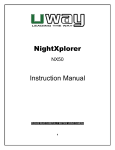
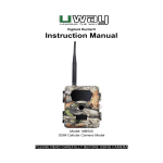
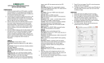
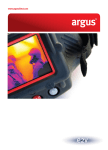
Thank you for purchasing the UWAY XtendIR universal infrared flash
extender product. You can now enjoy many benefits of using the XtendIR
with popular infrared game cameras to improve flash range and image
quality. This product is designed to operate in synchronicity with your
infrared camera in both photo and movie modes. This product utilizes high
quality and high output LEDs designed to provide maximum viewing range.
Optimal results will be obtained when using the guidelines covered in this
manual.
6V External power
The XtendIR provides a port for an external 6V,3A power source. External
battery cables and power station are sold separately. When the external
power port is used, the internal batteries are shunted. This means that the
unit will operate from either internal or external but not a combination.
Optimal performance should be achieved with a 6V SLA (Sealed Lead Acid)
type battery.
FEATURES (see diagram A)
Uway Flash Extender User's Manual
(XtendIR-I)
- Day/Night Light Sensor
- LED Bank 1 Main Enhancement Bank 36 LEDS
- LED Bank 2 Wide-Angle Bank 36 LEDS
- LED Bank 3 Distance Bank 18 LEDS
- Sensor Plug Port
SPECIFICATIONS
- 90 High Output LED Array
- Main Enhancement LED Bank (36 Leds)
- Wide Angle Illumination Bank (36 Leds)
- Distance Illumination Bank (18 Leds)
- Adjustable illumination from 45 to 120+ feet (standalone)
- 3 foot Infrared Sensor Cable connects to ALL IR cameras
- Functions in Photo and Movie Modes
- Uses 4 "D" Cell Batteries Internal
- 6 Volt External Battery port
- Innovative Curved rear mounts provide both mounting and security
using strap, bungee and python lock
- Adjust angles up and down for easy camera alignment
- Brown Anti-Reflective Color Surface
- Patent Pending
KIT INCLUDES
- XtendIR Main Unit
- Sensor Cable
- Cinch Strap
- Users Manual
POWER
“D” Batteries
The XtendIR requires 4 type “D” batteries. Alkaline batteries will provide
optimal power and operate the unit to its maximum capacity. Although
rechargeable “D” cells have lower voltage, they are also a good battery
source for XtendIR. The performance and battery lifetime (per charge) will
depend on the capacities (MAH) of the rechargeable cells.
Install the batteries according to the instructions in the XtendIR case. Proper
polarity must be followed to operate the unit.
Day/Night Light Sensor
Infrared Flash Extender
Bank 3
(Distance Bank)
Bank 2
(Wide-Angle Bank)
Bank 1
(Main Enhancement Bank)
Light up the night
X tendIR I
Sensor Plug
Day/Night Sensor:
This sensor should not be blocked during operation. It is used to determine
the amount of ambient light available and to disable the unit when it is
sufficiently light. The LUX on this sensor is designed to make the XtendIR
more sensitive to daylight by approximately 30 minutes than the average
camera. This design was employed to avoid whiteout or washout during
transition lighting periods such as early morning and late evening. During
these time periods the camera LEDs should be sufficient and the XtendIR
will begin to operate when ambient conditions are darker.
LED Bank 1:
This bank is the default bank of LEDs and considered the “enhancement
bank”. It is composed of 36 LEDs which provide standard image
enhancement. This bank is activated by flipping the POWER (white) switch
to the ON position.
Note: the POWER (white) switch is the main power control switch. When in
the OFF position the device is powered OFF (regardless of bank 2 and 3
switches).
LED Bank 2:
This bank is considered to be the “wide angle bank” and is also composed of
36 LEDs. The purpose of this bank is to not only enhance the center of the
image but push extra flash into the periphery of the image. Activate this bank
by flipping the BANK 2 switch to the ON position.
LED Bank 3:
This bank is considered to be the “distance illumination bank”. It is
composed of 18 LEDs with a narrow, more focused range. The effect is to
push more illumination into the center of the image. Activate this bank by
flipping the BANK 3 switch to the ON position.
A note on battery consumption:
Using banks 2 and 3 will increase the power consumption of the device. In
order to gain longer battery life, use fewer banks when they are sufficient.
For camera in video mode, when multiple banks are needed (especially
three banks), it is recommended setting the video length to no more than 60
seconds.
OPERATION
Open the bottom cover to reveal switch panel & battery compartment. (See
diagram B).
- Sensor Port
- POWER Switch
- BANK 2 Switch
- BANK 3 Switch
- Battery Indicator Button
- Battery Indicator LEDs 1 and 2
- 6V DC External Power Port
- Battery Compartment Door
To operate the XtendIR, provide power using either internal “D” cells or
External 6V power via external cable and battery. Select a combination of
banks (2 and/or 3 or neither) to suit your illumination needs and battery
conservation requirements, flip the POWER switch to ON. Slide the bottom
cover door shut. See POWER section for more information on batteries.
Insert the Sensor arm into the sensor port gently but with firm pressure to
ensure a good contact. Press until the cable slides in all the way.
Mount the XtendIR near the camera, attach the sensor arm cup (see diagram
C) over the LED array of the camera.
The sensor cup should be placed as nearly directly over an LED on the
camera as possible for optimal triggering. Use a square segment of Velcro
on your camera or nearby to anchor the sensor arm in place. Bend the
sensor cup in place over the LED array of the camera.
MOUNTING
Optimal results can be achieved by mounting the XtendIR in the same plane
as the camera. This means they should be aimed as closely as possible in
the same direction. Tests reveal that a parallel mounting will improve
reflective illumination from the LEDs. (See Diagram C)
Parallel Pointing
(Recommended)
Parallel Pointing
(Recommended)
Tilting upward
Tilting downward
(Not recommended) (Not recommended)
There are three ways to mount the XtendIR.
- A cinch strap
- A bungee cord
- A locking cable
The curved rear mounts allow for easy angle adjustments up and down when
mounting the unit. A strap or bungee cord is enough to hold the unit in place
while a locking cable is inserted to secure the unit.
TROUBLESHOOTING
Testing the Battery:
Turn off the POWER switch, then test the battery by pressing the Battery
Indicator button. The two LEDs will indicate the current battery strength and
level for the current power source (internal or external battery). Two lit
battery indicator LEDS means High strength. One LED lit indicates that the
battery is less than 30%. At this point, it is better to use fewer banks such as
one (recommended) or two (illumination may degrade). No LEDs indicates
battery is dead.
Note 1: When testing the battery using the Test Button (see Diagram B) the
main LED Bank will light up. This places the batteries under a load to
produce a more realistic battery level. In the dark this will also stand as a
visual aid to let you know the unit is functioning. Releasing the Test Button,
the main LED bank will be off in 2-3 seconds.
Note 2: The above battery checking method is based on the voltage level,
which is most suitable for alkaline cells and external 6V power station. For
rechargeable “D” cells, due to the initial lower voltage (4.8V), the one LED lit
may show up earlier when the batteries are still strong.
Photos or Videos are too bright:
One option is to use fewer banks on the XtendIR which will reduce the
amount of light produced and reflected into the camera lens. Another option
is to move the unit and camera farther away from the target subjects.
Poor Illumination:
Ensure that the XtendIR and the camera are aimed in parallel (in the same
direction). This will improve the reception of the IR emissions from the
XtendIR by the camera's lens. Poor illumination may also result from low
battery level, check it according to the procedures stated in the earlier
sections.
Unstable Illumination:
This may happen when the battery level is very low and multiple banks are
turned on. You may observe the flickering of LEDs or banks. At this stage, just
use the main LED bank or change the batteries.
This may also happen when the camera is in long minute video mode and
multiple banks are turned on, XtendIR is designed with a built-in self-protect
mechanism against overheating. Shortening the video length will resolve this
issue.
Limited Warranty
The unit purchased from our authorized dealer is warranted to be free from
defects in material and workmanship for 1 year of the original purchase under
normal use. Uway, will, at its option, repair or replace your product, with the
same or comparable model free of charge (except you must pay for shipping
charges set forth below) for a period of (1) one year from the date of original
purchase in the event of a defect in materials or workmanship occurring
during normal use. This warranty only extends to the original retail purchaser.
Purchase receipt or other proof of date of original purchase is required before
warranty performance. The warranty on any replacement product provided
under this warranty shall be for the unexpired portion of the warranty period
applicable to the original product.
This warranty extends solely to failures due to defects in materials or
workmanship occurring during normal use. It does not cover normal wear of
the product. This warranty is void if: the product housing has been removed, if
the product's label, logo or serial number have been removed or if the product
fails to function properly as a result of accident, misuse, abuse, neglect,
mishandling, misapplication, non-compatible batteries, faulty installation,
setup, adjustments, improper maintenance, alteration, maladjustment of
controls, modification, power surges, service by anyone other than Uway or
Uway authorized service center or acts beyond the manufacturer's or
distributor's control.
Should your product prove defective during this warranty period, please
contact Uway and follow the instructions. *RMA number is required for all
returns.
Include $11.95 for return shipping & insurance. (For U.S. customers only.
Check or money order only, non-refundable). If the unit is out the warranty,
the price for repairing or replacing may vary. Please allow 6-8 weeks for
delivery. Customers out of U.S. pay different amount of shipping & insurance.
We will send detailed information along with the RMA number.
Include with your product the RMA form and a copy of your dated cash
register receipt or other proof of purchase.
*Please consult your dealer or us if you have any question or
problem while you use the unit before you request a RMA number
and send the unit back for repair. Some problem may easily be
solved with help from our dealer or us.
LEADING THE WAY
3120 Medlock Bridge Road, Suite H400
Norcross, GA, 30071 U.S.A.
1-770-582-0004 (TEL), 1-803-334-4505 (FAX)
[email protected]
http:// www.uwayoutdoors.com
Made by Uway, your technology leader, “Leading the Way!”