1
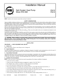
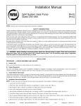
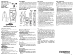
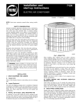
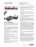
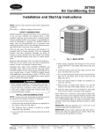
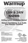
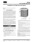
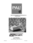
Installation
Manual
Electric Air Conditioner
018-060 PAl0
018-060 PAl2
NOTE:
Read the entire
instruction
manual
before
starting
the installation.
service,
maintenance,
SAFETY
improper
installation,
adjustment,
alteration,
PAl 0
PAl2
CONSIDERATIONS
or use can cause explosion,
cause death, personal injury, or property damage. Consult a qualified
assistance.
The qualified installer or agency must use factory-authorized
instructions
packaged
with the kits or accessories
when installing.
fire, electrical
shock, or other conditions
which may
installer, service agency, or your distributor
or branch for information
or
kits or accessories
when modifying
this product. Refer to the individual
Follow all safety codes. Wear safety glasses, protective
clothing,
and work gloves. Use quenching
cloth for brazing operations.
extinguisher
available.
Read these instructions
thoroughly
and follow all warnings or cautions
included in literature and attached
Consult local building
codes and National Electrical Code (NEC) for special requirements.
Recognize
safety information.
This is the safety-alert
to the potential
for personal injury.
Understand
the signal
words
DANGER,
symhol_
WARNING,
. When
CAUTION,
AND
you see this symbol
NOTE.
These
on the unit and in instructions
words
are used with the safety*alert
Have fire
to the unit.
or manuals,
symbol.
be alert
DANGER
identifies the most serious hazards which will result in severe personal injury or death. WARNING
signifies hazards which could result in personal
injury or death. CAUTION
is used to identify unsafe practices which would result in minor personal injury or product and property damage. NOTE
is used to highlight
suggestions
which will result in enhanced
installation,
reliability,
or operation.
_X WARNING:
Before installing or servicing system, always turn off main power to system. There may be more than 1
disconnect switch. Turn off accessory heater power if applicable. Electrical shock can cause personal injury or death.
INSTALLATION
NOTE:
In some cases
noise
I. Locate
unit away
2. Ensure
that vapor-
3. Run refrigerant
4. Leave
some
5. When
passing
6. Avoid
direct
9. When
I0.
Isolate
from
windows,
slack between
refrigerant
tubing
hanger
tubes
contact
insulation
use hanger
straps
decks,
diameters
as possible
structure
refrigerant
that tubing
necessary,
patios,
as directly
RECOMMENDATIONS
area has been traced to gas pulsations
and liquid-tube
tubes
7. Do not suspend
8. Ensure
in the living
and so forth, where
are appropriate
by avoiding
through the wall,
with
water pipes,
tubing
from joists
is pliable
straps
from insulation
by using
to capacity
installation
sound
of equipmant.
may disturb
customer.
silicon-based
caulk.
(See Fig. 1.)
contact
with tubing.
of unit.
turns and bends.
vibration.
seal opening
duct work,
with RTV
floor joists,
or other pliable
wall studs,
floors,
and studs with a rigid wire or strap
and completely
which are
improper
unit*operation
unnecessary
and unit to absorb
from
surrounds
I in. wide
vapor
and conform
metal sleeves
and walls.
that comes
in direct
(See Fig.
1.)
tube=
to shape
bent to conform
of tubing
to shape
insulation.
(See Fig.
I.)
of insulation.
Z_
CAUTION: DO NOT BURY MORE THAN 36 IN. OF REFRIGERANT TUBING IN GROUND. If any section of tubing is
buried, there must be a 6-in. vertical rise to valve connections on outdoor unit. If more than recommended length is buried,
refrigerant may migrate to cooler buried section during extended periods of unit shutdown, causing refrigerant slugging and
possible compressor damage at start-up.
INSTALLATION
PROCEDURE
A.
I--CHECK
EQUIPMENT
AND JOB SITE
Unpack Unit
Move to final location. Remove carton taking care not to damage unit.
B.
Inspect Equipment
File claim with shipping company prior to installation if shipment is damaged or incomplete. Locate Emitrating plate on unit control box access
panel. It contains information needed to properly install unit. Check rating plate to be sure unit matches job specifications.
Form:
IM-PA10-05
Cancels:
IM-PA10-04
Printed in U.S,A,
3-03
Catalog No.
53PA-1017
NOTE:
Avoid
contact
between
tubing
andstructure
_--OUTDOOR
WALL-_ INDOOR
WALL7
_ CAULK
IQUID
TUBE
LINSULATIO
N__
_/__ _ VAPOR
TUBE
THROUGH THE WALL
HANGER STRAP'_k
,,_
(AROUNDTuBEVAPOR_oNLY)
_, _
_1
JOIST
_
INSULATION
( i ]_
--vAPOR
TUBE
LIQUID TUBE
SUSPENSION
A94028
Fig. liOonnecting
NOTE:
against
NOTE:
contact
Check
each
to be certain
tubing
other or any sheet metal.
Check
factory
with tubing,
PROCEDURE
if conditions
wiring
sheet
or local codes
members
Tubing
and outdoor
Pay close attention
to feeder
to ensure
Installation
unit has not been shifted
tubes,
making
terminations
sure wires
are secured
during
shipment.
on feeder
properly.
tubes
Check
Ensure
are secure
wire routing
tubes
are not rubbing
and tight.
to ensure
wires are not in
etc.
ON A SOLID,
require
to unit mounting
supporting
on both indoor
and wire connections
metal,
2ilNSTALL
base pan. Refer
Arrange
factory
LEVEL
MOUNTING
the unit be attached
pattern
to pad, tie down
in Fig. 2 to determine
to adequately
support
PAD
bolts
should
be used
base pan size and knockout
unit and minimize
transmission
and fastened
through
knockouts
provided
in unit
hole location.
of vibration
to building.
Consult
local codes governing
rooftop
applications.
NOTE:
Unit must be level to within
PROCEDURE
When
± 2 ° (± 3/8 in./ft).
3--CLEARANCE
installing,
allow
sufficient
REQUIREMENTS
space
for airflow
and 48 in. above unit. For proper airflow,
distance of 24 in. between units. Position
On rooftop
applications,
PROCEDURE
The minimum
locate
unit at least 6 in. above
4--OPERATING
outdoor
PROCEDURE
clearance,
operating
5---REPLACE
wiring,
refi'igerant
piping,
and service.
Allow
30*in. clearance
a 6-in. clearance
on 1 side of unit and 12 in. on all remaining
sides must
so water, snow, or ice from roof or eaves cannot tall directly on unit.
AMBIENT
ambient
end of unit
Maintain
a
roof surface.
(OUTDOOR
in cooling
INDOOR
to service
be maintained.
mode
TEMPERATURES)
is 55°F ", and the maximum
CHECK*FLO*RATER®
PISTON,
outdoor
operating
ambient
in cooling
mode
is 125°F ".
IF REQUIRED
Check indoor coil piston to see if it matches the required piston shown on outdoor unit rating plate. If it does not match, replace indoor coil piston
with piston shipped with outdoor unit. The piston shipped with outdoor unit is correct for any approved
indoor coil combination.
PROCEDURE
6--MAKE
REFRIGERANT
Outdoor units may be connected
to indoor
condition.
For tubing requirements
beyond
tubing
to fittings
if refrigerant
contamination
A.
factory
unit
vapor
and liquid
tubes or indoor coil is exposed
and moisture
Outdoor
Outdoor
on outdoor
accessory
Z_x
CAUTION:
wet cloth.
correct
tubing.
CONNECTIONS
service
to atmospheric
valves.
tubing package or field*supplied
refrigerant
grade tubing of correct
Application
Guideline which is available at your local distributor.
(See Table
conditions
size and
Connect
1.)
for longer
than 5 minutes,
it must be evacuated
to 500 microns
to eliminate
in system.
Unit Connected
unit contains
TUBING
sections using accessory
50 ft, consult Long-Line
to Factory
system
Check
refrigerant
refi'igerant
To avoid valve
Approved
charge
charge
damage
Indoor
for maximum
while
Unit
for operation
brazing,
with indoor
efficiency.
service
....
2m.
unit of same size when connected
(See Procedure
valves
must
11--Check
be wrapped
by 15 fl of field*supplied
or
Charge.)
with a heat*sink
material
such
as a
AIR IN
3/8" DIA, TIEDOWN
KNOCKOUTS
A01340
UNIT SIZE
PAl 0 060
PAl2 024 - 060
C
D
In.
In,
10
PAl0 018 - 048
PAl2 018
22-1/2
18-1/2
Fig. 2--Unit
6-1/2
8-3/16
4-1/16
Dimensions
DISCONNECT
PER N.E,C. AND/OR
LOCAL CODES
CONTACTOR
FIELD
POWER
WIRING
©
FIELD
GROUND
WIRING
GROUND
LUG
A88174
B.
Fig. 3---Line Power Connections
Sweat Connection
Use refrigerant grade tubing. Service valves are closed from factory and ready for brazing. After wrapping service valve with a wet cloth, braze
sweat connections using industry accepted methods and materials. Consult local code requirements. Refrigerant tubing and indoor coil are now
ready for leak testing. This check should include all field and factory joints.
PROCEDURE
7--MAKE ELECTRICAL CONNECTIONS
WARNING:
removed.
Be sure field wiring
To avoid personal
complies
injury or death, do not supply power to unit with compressor
with local and national
fire, safety,
plate. Contact local power company for correction
of improper
NOTE:
Operation
of unit on improper line voltage constitutes
system
where
voltage
NOTE:
Use copper
NOTE:
Install branch
or phase
imbalance
wire only between
circuit
disconnect
(3 phase)
disconnect
of adequate
and electrical
and voltage
to system
is within
limits
shown
on unit rating
voltage. See unit rating plate for recommended
circuit protection
device_
abuse and could affect unit reliability.
See unit rating plate. Do not install unit in
may fluctuate
switch
codes,
terminal box cover
above
or below
permissible
limits.
and unit.
size per NEC to handle
unit starting
current.
Locate disconnect
within
sight from and readily
accessible
from unit, per Section 440-14 of NEC.
A.
Route Ground and Power Wires
Remove
access
panel to gain access
to unit wiring.
Extend
wires
from disconnect
through
power
wiring hole provided
and into unit control
box.
Z_ WARNING:
According to NEC, ANSIINFPA 70, and local codes, cabinet must have an uninterrupted or unbroken
ground to minimize personal injury if an electrical fault should occur. The ground may consist of electrical wire or metal
conduit when installed in accordance with existing electrical codes. Failure to follow this warning can result in an electric
shock, fire, or death.
B.
Connect Ground and Power Wires
Connect ground wire to ground connection in control box for safety. Connect power wiring to contactor as shown in Fig. 3.
....
3___
Table 1--Refrigerant
Connections and Recommended
LIQUID
UNIT SIZE
Connect
Diameter
Tube
Diameter
Connect
Diameter
Tube
Diameter
018, 024
3/8
3/8
3/8
5/8
030, 036
042-048
3/8
3/8
3/8
3/8
3/8
7/8
3/4
7/8
3/8
3/8
060
Note: Tube diameters
C.
Liquid and Vapor Tube Diameters (in.)
VAPOR
Connect
7/8
are for lengths up to 60 ft. For tubing lengths greater than 60 ft, consuR your IocN distributor
Control
1-1/8
or Long-Line Application
Guideline.
Wiring
Route 24-v control wires through control wiring grommet and connect leads to control wiring. (See Fig. 5.) Use No. 18 AWG color*coded,
insulated (35°C minimum) wire. if themlostat is located more than I00 ft from unit, as measured along the control voltage wires, use No. 16 AWG
color coded wire to avoid excessive voltage drop.
Use furnace transformer, f_ancoil transfomler, or accessory transformer
for control power, 24-v/40*va minimum.
NOTE: Use of available 24-v accessories may exceed the minimum 40*va power requirement. Determine total transformer loading and increase
the transformer capacity or split the load with an accessory transformer as required.
PROCEDURE
8--COMPRESSOR
CRANKCASE
HEATER
A crankcase heater is required if refrigerant tubing is longer than 50 It.
PROCEDURE
9iINSTALL
ELECTRICAL
ACCESSORIES
Refer to the individual instructions packaged with kits or accessories
PROCEDURE
•
•
•
•
when installing.
10iSTART*UP
CAUTION:
3*phase scroll compressors are rotation sensitive.
A flashing LED on phase monitor indicates reverse rotation. (See Fig. 4 and Table 2.)
This will not allow contactor to be energized.
Disconnect power to unit and interchange 2 field wiring leads on unit contactor.
I. When equipped with a crankcase heater, energize heater a minimum of 24 hr before starting unit. To energize heater only, set thermostat
to OFF mode and close electrical disconnect to outdoor unit.
CAUTION: Service valve gage ports are equipped
glasses and gloves when handling refrigerant.
2. Fully
back seated
3. Unit is shipped
Replace
4. Close
(open)
5. Set room
and vapor
with valve stem(s)
caps finger-tight
electrical
liquid
thermostat
front seated
and tighten
disconnects
to energize
at desired
6. Set room thermostat at COOL
Check Charge section.
service
additional
with Schrader
valves. To prevent
personal
injury, wear safety
valves.
(closed),
and caps installed.
Replace
stem caps after
system
is opened
Check
system
to refi-igerant
flow.
1/6 turn with wrench.
system.
temperature.
Be sure set point is below
and fan ON or AUTO
modes,
as desired.
indoor
Operate
ambient
temperature.
unit for 15 minutes.
refrigerant
charge.
See
WARNING:
Relieve pressure and recover all refrigerant before system repair or final unit disposal to avoid personal
injury or death. Use all service ports and open all flow control devices, including solenoid valves.
A.
Sequence
of Operation
Turn on power to indoor and outdoor units. Transformer
is energized.
On a call for cooling, thermostat makes circuits R-Y and R-G. On three phase models with scroll compressors, the units are equipped with a phase
monitor to detect if the incoming power is correctly phased for compressor operation. (See Fig. 4 and Table 2.)if the phasing is correct, circuit
R-Y energizes contactor, starting outdoor fan motor and compressor circuit. R-G energizes indoor unit blower relay, starting indoor blower motor
on high speed.
NOTE: if the phasing is incorrect, the contactor will not be energized. To correct the phasing, interchange any two of the three power connections
on the field side.
When thermostat
is satisfied, its contacts open, de-energizing
contactor and blower relay. Compressor and motors stop.
if indoor unit is equipped with an off delay circuit, the indoor blower can run up to an additional
.==_.
....
120 sec to increase system efficiency.
BDHTACTDR
24VAC
COM
OFF:NO
ON:OK
FLASH:PHASE
O
24VAC
PROBLEM
0
@
L3
L1
A00010
Fig. 4i3
Table
Phase Monitor Control
2--Phase
Monitor
LED
Indicators
LED
STATUS
OFF
No call for compressor
FLASHING
ON
PROCEDURE
A.
II--CHECK
operation
Reversed phase
Normal
CHARGE
Unit Charge
Factory charge is shown on unit rating plate. (See Fig. l.)Charge procedure is shown on wiring/charging
CAUTION:
Compressor
CAUTION:
Do not vent refrigerant to atmosphere.
label located on unit.
damage may occur if system is overcharged.
Recover during system repair or final unit disposal.
CARE AND MAINTENANCE
For continuing
equipment.
depending
Leave
high
performance,
and to minimize
possible
equipment
Consult your servicing contractor
or User's
Manual
upon geographic
areas, such as costal applications.
User's
Manual
with homeowner.
Explain
system
operation
failure,
for proper
and maintenance
.....
5 ....
it is essential
frequency
that periodic
of maintenance.
procedures
outlined
maintenance
Frequency
in manual.
be performed
of maintenance
on this
may vary
AC ELECTRONIC
THERMOSTAT
SINGLE-STAGE
COO_HEAT
24 VAC HOT
_
....
AC ELECTRONIC
THERMOSTAT
SINGLE-STAGE
COOL/HEAT
AIR
CONDITIONER
HEAT STAGE 1
COOL STAGE 1
FAN
.....
[_-"
(c)
HEAT STAGE 1
[] ..... _B-.....
E} .... D
COOL STAGE 1
iNDOOR
AIR
CONDITIONER
J
L--I
I_
i
[][]
[]
M-
24 VAC COM
V
PF
FAN COIL
L_
24 VAC HOT
_
171.... D ---- _'-
24 VAC COM
INDOOR
SINGLE-STAGE
FURNACE
FAN
A01331
ACTHERMOSTAT
SINGLE-STAGE
COO_HEAT
A01332
AC THERMOSTAT
SINGLE - STAGE
COOL/HEAT
SINGLE-STAGE
FURNACE
STAGE
COOL
STAGE
iNDOOR
[_-
HOT
HEAT
AIR
CONDITIONER
AIR
CONDITIONER
24 VAC HOT
24 VAC
PF
FAN COIL
__ J_t_,
HEATSTAGE
1
1
FAN
£]-.
(c)
1 [_
COOL STAGE 1 E_
D
INDOOR FAN
E_-
A01333
A01334
Fig. 5--Typical
© 2003 Payne Heating & Cooling
7310 W. Morris St., indianapolis,
iN 46231
24v Circuit Connections
-m-d----
impal005
Catalog
No. 53PA-1017