1
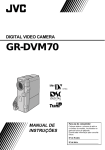
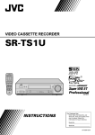
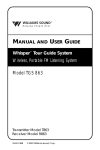
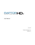
66 EN
USING THE REMOTE CONTROL UNIT (cont.)
MAKE CONNECTIONS
Also refer to pg. 54 and 55.
1
To AV
... connect the editing cable to the Remote
PAUSE connector.
A JVC VCR not equipped with a remote
pause connector but equipped with an
R.A.EDIT connector . . .
Connector
cover**
To EDIT
A JVC VCR equipped with a remote pause
connector . . .
... connect the editing cable to the R.A.EDIT
connector.
To
S-VIDEO
A VCR other than above . . .
... connect the editing cable to the remote
control’s PAUSE IN connector.
Editing
cable
(provided)
S-Video
cable
(provided)
Audio/Video
cable
(provided)
White to
AUDIO L IN
To
S-VIDEO IN
To Remote
PAUSE or
R.A.EDIT
Red to
AUDIO R
IN
Yellow to
VIDEO
IN*
VCR
To PAUSE IN
TV
DISPLAY
2
Insert a recorded tape into the camcorder and set the
Power Switch to “
” while pressing down the
Lock Button located on the switch.
3
Turn the VCR power on, insert a recordable tape and
engage the AUX mode (refer to the VCR’s instructions).
NOTES:
● Before Random Assemble Editing, make sure the
indications do not appear on the TV monitor. If they do,
they will be recorded onto the new tape.
To choose whether or not the following displays appear
on the connected TV . . .
•Date/Time
..... set “DATE/TIME” to “AUTO”, “ON” or “OFF” in the
Menu Screen ( 墌 pg. 41).
•Time Code
..... set “TIME CODE” to “ON” or “OFF” in the Menu
Screen (墌 pg. 41).
•Playback Sound Mode, Tape Speed And Tape Running
Displays
..... set “ON SCREEN” to “LCD” or “LCD/TV” in the
Menu Screen ( 墌 pg. 41). Or, press DISPLAY on the
remote control.
● When editing on a VCR equipped with a DV input
connector, an optional DV cable can be connected
instead of an S-Video cable and audio/video cable.
* Connect when an S-Video cable is not used.
** When connecting cables, open this cover.
JY-VS200U EN 66-95
66
01.3.12, 7:31 PM
EN
SELECT SCENES
Program
IN
1–– –– : ––
2
3
4
5
6
7
8
T I ME CODE
TOTAL
67
MODE
OUT
~
~
~
~
~
~
~
~
Random Assemble
Editing Menu
–– : ––
0 0 : 00
Remote sensor
PLAY
FADE/WIPE
EFFECT
EDIT IN/OUT
R.A.EDIT
ON/OFF
4
Point the remote control at the camcorder ’s remote
sensor. Press PLAY (4) and then press R.A.EDIT ON/
OFF on the remote control.
The Random Assemble Editing Menu appears.
5
If using a Fade/Wipe at the beginning of the scene,
press FADE/WIPE on the remote control.
•Cycle through the effects by pressing repeatedly ,
and stop when the one you want is displayed.
•You cannot use a Picture Wipe/Dissolve at the
beginning of Program 1.
6
At the beginning of the scene, press EDIT IN/OUT on
the remote control. The Edit-In position appears in
the Random Assemble Editing Menu.
7
At the end of the scene, press EDIT IN/OUT. The
Edit-Out position appears in the Random Assemble
Editing Menu.
8
If using a Fade/Wipe at the end of the scene, press
FADE/WIPE.
•Cycle through the effects by pressing repeatedly ,
and stop when the one you want is displayed.
•If you select a Fade/Wipe effect for an Edit-Out
point, the effect is automatically applied to the
following Edit-In point.
•You cannot use a Picture Wipe/Dissolve at the end
of the last scene.
•When you use Fade/Wipe effects, that time is
included in the total time (this does not apply to
Picture Wipe/Dissolve). 1
9墌
10
If using Playback Special Effects, press EFFECT
(
pg. 64).
Repeat steps 6 through 9 to register additional scenes.
•To change previously registered points, press
CANCEL on the remote control. The registered
points disappear, one at a time, from the most
recently registered point.
•If you are not using Fade/Wipe or Program AE with
special effects, repeat steps 6 and 7 only.
CANCEL
NOTES:
● When choosing a scene, set Edit-In and Edit-Out points so that there is a relatively lar ge difference between
them.
● If the search time for an in-point exceeds 5 minutes, the recording deck’ s Record-Standby mode will be
canceled and editing will not take place.
● If there are blank portions before or after the Edit-In and Edit-Out points, a blue screen may be included in
the edited version.
● Since time codes register time only as accurately as seconds, the time code total time may not match the
total program time exactly.
● Turning off the camcorder ’s power erases all registered Edit-In and Edit-Out points.
● If you select Sepia or Monotone mode from Program AE with special effects, you cannot use the Dissolve or
Black & White Fader. In this case the Dissolve or Black & White indicator begins blinking. Once the next
Edit-In point is registered, the effect is turned off. T o combine these effects, use Sepia or Monotone during
recording, then use the Dissolve or Black & White Fader during Random Assemble Editing.
● It is not possible to use Fade/Wipe effects and Program AE with special effects during Random Assemble
Editing using a DV cable.
JY-VS200U EN 66-95
67
01.3.12, 7:31 PM
68 EN
USING THE REMOTE CONTROL UNIT (cont.)
AUTOMATIC EDITING TO VCR
11
12
~
~
~
~
~
~
~
~
OUT
MODE
02 : 05
––
08 : 31 – – – –
05 : 53
13 : 15
16 : 29 – – – –
Press the Recording Start/Stop Button on the
camcorder. Editing proceeds as programed, right
through to the end of the last registered scene.
•Pressing START/STOP on the remote control does
not start editing.
•When dubbing is complete, the camcorder enters
the Pause mode, and the VCR enters its RecordPause mode.
•If you do not register an Edit-Out point, the tape will
be dubbed all the way to the end automatically .
•If you operate the camcorder during automatic
editing, the VCR will enter its Record-Pause mode
and automatic editing will stop.
14
Engage the Stop modes for the camcorder and the
VCR.
To make the R.A.Edit counter display disappear, press
R.A.EDIT ON/OFF on the remote control.
Random Assemble
Editing Menu
16 : 30
9 : 39
Remote Sensor
Point the remote control towards the VCR’ s remote
sensor and press VCR REC STBY (q6), or manually
engage the VCR’s Record-Pause mode.
13
Recording Start/Stop Button
IN
00 : 2 5
1
2
07 : 18
3 – – 0 3 : 33
09 : 30
4
5
15 : 55
6–– –– : ––
7
8
T I ME CODE
TOTAL
Rewind the tape in the camcorder to the beginning of
the scene you want to edit and press PAUSE (6).
1
NOTES:
● Pressing R.A.EDIT ON/OFF on the remote control clears
all settings registered during Random Assemble Editing.
● When the editing cable is connected to the remote
control’s Pause In connector during dubbing, make sure
the remote control is pointed at the VCR’ s sensor, and
the path between the two is unobstructed.
● Random Assemble Editing may not function properly
when using a tape including several duplicated time
codes ( 墌 pg. 23).
CONTINUED ON NEXT PAGE
REW
FADE/WIPE
EFFECT
EDIT IN/OUT
CANCEL
JY-VS200U EN 66-95
STOP
PAUSE
R.A.EDIT
ON/OFF
VCR REC
STBY
68
01.3.12, 7:31 PM
EN
For More Accurate Editing
Program 1
IN
1–– –– : ––
2
3
4
5
6
7
8
T I ME CODE
TOTAL
OUT
~
~
~
~
~
~
~
~
TV
69
MODE
Random Assemble
Editing Menu
–– : ––
0 0 : 00
Some VCRs make the transition from Record-Pause to
Record mode faster than others. Even if you begin editing
for the camcorder and the VCR at exactly the same time,
you may lose scenes you wanted, or find that you have
recorded scenes you did not want. For a cleanly edited
tape, confirm and adjust the timing of the camcorder
against your VCR.
DIAGNOSING VCR/CAMCORDER TIMING
VCR
(Recording deck)
1
Play back the tape in the camcorder, then point the
remote control at the camcorder ’s remote sensor and
press R.A.EDIT ON/OFF.
The Random Assemble Editing Menu appears.
2
Perform Random Assemble Editing on Program 1
only. In order to check VCR and camcorder timing,
select the beginning of a scene transition as your EditIn point.
3
Play back the dubbed scene.
•If any images from the scene prior to the
transition you chose for your Edit-In point were
recorded, that means your VCR moves too quickly
from Record-Pause to Record mode.
•If the scene you tried to dub starts in progress, the
VCR is slow to start recording.
Remote sensor
R.A.EDIT ON/OFF
JY-VS200U EN 66-95
69
CONTINUED ON NEXT PAGE
01.3.12, 7:31 PM
70 EN
USING THE REMOTE CONTROL UNIT (cont.)
ADJUSTMENT OF VCR/CAMCORDER
TIMING
Display
SYNCHRO
TV
–
O. 1
VCR
(Recording deck)
Point the remote control at the camcorder ’s remote
sensor and press R.A.EDIT ON/OFF to make the
Random Assemble Editing menu disappear, then
press the MENU wheel. The Menu Screen appears.
5
Rotate the MENU wheel to select “
VIDEO” and
press it. The VIDEO Menu appears. Then, rotate it to
“SYNCHRO” and press it. The value for “SYNCHRO”
is highlighted.
6
Based on the diagnostics performed ( 墌 pg. 69), you
can now advance the VCR’s record timing by rotating
the MENU wheel towards “+”. You can also delay the
VCR’s record timing by rotating the MENU wheel
towards “–”. The adjustment range is from –1.3 to
+1.3 seconds, in 0.1-second increments.
Press the MENU wheel to finish the setting.
7
Rotate the MENU wheel to select “1RETURN” and
press it twice.
Now perform Random Assemble Editing beginning
with step 4 on page 67.
NOTES:
● Before performing actual Random Assemble Editing, do
a few Random Assemble Editing trial runs to check
whether the value you have input is appropriate or not,
and make adjustments accordingly.
● Depending on the recorder, there may be situations
where the timing difference cannot be fully corrected.
MENU Wheel
JY-VS200U EN 66-95
4
70
01.3.12, 7:31 PM
EN
71
Audio Dubbing
Display
6e
Audio Dub
Standby mode
The audio track can be customized only when recorded in
the 12-bit mode ( 墌 pg. 29).
NOTES:
● Audio Dubbing is not possible on a tape recorded in 16bit audio, on a tape recorded in the LP mode or on a
blank portion of a tape.
● To perform Audio Dubbing while watching on the
television, make connections ( 墌 pg. 54).
Power Switch
PHONE
(headphone)
connector*
MIC (external
microphone
input) connector*
Stereo
microphone
DISPLAY
A.DUB
PAUSE
STOP
* Located beneath the cover.
JY-VS200U EN 66-95
Play back the tape to locate the point where editing
will start, then press PAUSE (6).
4
To end Audio Dubbing, press PAUSE (6), then STOP
(5).
While holding A.DUB (e) on the remote control,
press PAUSE (6). “6e” appears.
Press PLAY (4) , then begin “narrating”.
Speak into the microphone.
•To pause dubbing, press PAUSE (6).
To hear the dubbed sound during playback . . .
.... set “12BIT MODE” to “SOUND 2” or “MIX” in the
Menu Screen ( 墌 pg. 41, 42).
Speaker
Remote sensor
PLAY
1
2
3
71
NOTES:
● Audio dubbing is also possible using an optional
microphone connected to the MIC connector .
● Sound is not heard from the speaker during Audio
Dubbing. To hear sound, connect optional headphones
to the PHONE connector.
● While an optional microphone is connected, the built-in
microphone is disabled.
● When editing onto a tape that was recorded at 12-bit,
the old and new soundtracks are recorded separately .
● If you dub onto a blank space on the tape, the sound
may be disrupted. Make sure you only edit recorded
areas.
● If feedback or howling occurs during TV playback, move
the camcorder’s microphone away from the TV, or turn
down the TV’s volume.
● If you change from 12-bit to 16-bit in mid-recording
and then use the tape for Audio Dubbing, it is not
effective from the point where 16-bit recording began.
● During Audio Dubbing, when the tape moves to scenes
recorded in the LP mode, scenes recorded in 16-bit
audio or a blank portion, Audio Dubbing stops
( 墌 pg. 87).
● To perform Audio Dubbing with a video unit connected
to the camcorder’s AV connector, first set “S/AV INPUT”
to “ON” in the Menu Screen ( 墌 pg. 41). You can hear
sound from the video unit using optional headphones.
01.3.12, 7:31 PM
72 EN
USING THE REMOTE CONTROL UNIT (cont.)
Insert Editing
Display
You can record a new scene into a previously recorded
tape, replacing a section of the original recording with
minimal picture distortion at the in and outpoints. The
original audio remains unchanged.
6w
NOTES:
● Before performing the following steps, make sure that
“TIME CODE” is set to “ON” in the Menu Screen
( 墌 pg. 41).
● Insert Editing is not possible on a tape recorded in the LP
mode or on a blank portion of a tape.
● To perform Insert Editing while watching in the
television, make connections ( 墌 pg. 54).
12 : 34
Power Switch
1
Play back the tape, locate the Edit-Out point and
press PAUSE (6). Confirm the time code at this point
(墌 pg. 42).
2
3
Press REW (2) until the Edit-In point is located, then
press PAUSE (6).
4
Press START/STOP to begin editing.
•Confirm the insert at the time code you checked in
step 1.
•To pause editing, press START/STOP. Press it again
to resume editing.
5
To end Insert Editing, press START/STOP, then STOP
(5).
Lock Button
Remote sensor
START/STOP
REW
STOP
JY-VS200U EN 66-95
INSERT
PLAY
PAUSE
72
Press and hold INSERT (w) on the remote control,
then press PAUSE (6). “6w” and the Time Code
(min.:sec.) appear and the camcorder enters InsertPause mode.
NOTES:
● Program AE with special effects ( 墌 pg. 36, 37) can be
used to spice up the scenes being edited during Insert
Editing.
● During Insert Editing, the date and time information
changes.
● If you perform Insert Editing onto a blank space on the
tape, the audio and video may be disrupted. Make sure
you only edit recorded areas.
● During Insert Editing, when the tape moves to scenes
recorded in the LP mode or a blank portion, Insert Edting
stops ( 墌 pg. 87).
01.3.12, 7:31 PM
TROUBLESHOOTING
EN
73
If, after following the steps in the chart below , the problem still exists, please consult your nearest JVC dealer .
The camcorder is a microcomputer-controlled device. External noise and interference (from a TV , a radio,
etc.) might prevent it from functioning properly . In such cases, first disconnect its power supply unit (battery
pack, AC Power Adapter/Battery Charger, etc.) and wait a few minutes; and then re-connect it and proceed
as usual from the beginning.
POSSIBLE CAUSES
CORRECTIVE ACTION
1. No power is supplied.
SYMPTOM
1. •The power is not connected
properly.
•The battery is dead.
•The LCD monitor is not open
fully or the viewfinder is not
pulled out when recording.
1. •Connect the AC Power
Adapter/Charger securely
(墌 pg. 9).
•Replace the dead battery
with a fully charged one
(墌 pg. 8, 9).
•Open the LCD monitor fully
or pull out the viewfinder.
2. “SET DATE/TIME!”
appears.
2. •The built-in clock’s
rechargeable lithium battery
is discharged.
•The previously set date/time
is erased.
2. •Connect the camcorder to
an AC outlet using the AC
Power Adapter/Charger for
over 24 hours to charge the
clock’s lithium battery
(墌 pg. 11).
3. Recording cannot be
performed.
3. •The tape’s erase protection
tab is set to “SAVE”.
•The Power Switch is set to
“
” or “OFF”.
•“TAPE END” appears.
•The cassette holder cover is
open.
3. •Set the tape’s erase
protection tab to “REC”
(墌 pg. 12).
•Set the Power Switch to
“ ” or “ ” (墌 pg. 14).
•Replace with new cassette
(墌 pg. 12).
•Close the cassette holder
cover.
4. There is no picture.
4. •The camcorder is not getting
power, or some other
malfunction exists.
4. •Turn the camcorder’s power
off and on again
(墌 pg. 18).
5. Some functions are not
available using the MENU
wheel.
5. •The Power Switch is set to
“ ”.
5. •Set the Power Switch to
“ ” (墌 pg. 14).
6. The focus does not adjust
automatically.
6. •Focus is set to the Manual
mode.
•The recording was done in a
dark place, or the contrast
was low.
•The lens is dirty or covered
with condensation.
6. •Set Focus to the Auto mode
(墌 pg. 27).
•Clean the lens and check
the focus again ( 墌 pg. 80).
CONTINUED ON NEXT PAGE
JY-VS200U EN 66-95
73
01.3.12, 7:31 PM
74 EN
TROUBLESHOOTING (cont.)
SYMPTOM
POSSIBLE CAUSES
7. The cassette will not load
properly.
7. • The cassette is in the wrong
position.
• The battery’s charge is low.
7. •Set it in the right position
(墌 pg. 12).
•Install a fully charged
battery ( 墌 pg. 8, 9).
8. The memory card will not
load properly.
8. • The memory card is in the
wrong position.
8. •Set it in the right position
(墌 pg. 13).
9. In the 5-Second mode,
recording ends before
5 seconds have elapsed.
9. • The 5-Second mode is set to
“ANIM.” in the Menu
Screen.
9. •Select “5S” in the Menu
Screen (墌 pg. 33).
10. Snapshot mode cannot be
used.
10. • The 16:9SQ. mode is
selected.
10. •Disengage the 16:9SQ.
mode (墌 pg. 30).
11. The color of Snapshot
looks strange.
11. • The light source or the
subject does not include
white. Or there are various
different light sources behind
the subject.
• The Sepia or Monotone
mode is activated.
11. •Find a white subject and
compose your shot so that it
also appears in the frame
(墌 pg. 20, 21).
•Turn off Sepia and Monotone (墌 pg. 36, 37).
12. The image taken using
Snapshot is too dark.
12. • Shooting was performed
under backlit conditions.
12. •Press the BACKLIGHT
Button (墌 pg. 38).
13. The image taken using
Snapshot is too bright.
13. • The subject is too bright.
13. •Set “PROGRAM AE” to
“SPOTLIGHT” in the Menu
Screen (墌 pg. 36).
14. Digital Zoom does not
work.
14. • 10X optical zoom is selected.
• The Shooting Mode Switch is
set to “XGA/VGA” or
“UXGA”.
• “PROGRAM AE” is set to
“VIDEO ECHO” in the Menu
Screen.
• “WIDE MODE” is set to “PSWIDE” in the Menu Screen.
• Multi-Analyzer 4 or MultiAnalyzer 9 was attempted
during Digital Zoom.
• Picture Wipe or Dissolve are
being used in a scene
transition.
14. •Set “ZOOM” to “40X” or
“300X” in the Menu Screen
(墌 pg. 29).
•Set the Shooting Mode
Switch to “VIDEO”
(墌 pg. 14, 22).
•Disengage the “VIDEO
ECHO” mode
(墌 pg. 22, 37).
•Disengage the “PS-WIDE”
mode (墌 pg. 30).
•Disengage Multi-Analyzer 4
or Multi-Analyzer 9
(墌 pg. 20).
•Wait until the Picture Wipe
or Dissolve effects are
completed (墌 pg. 22, 34).
15. Program AE with special
effects and Fade/Wipe
Effects do not work.
15. • The Power Switch is set to
“ ”.
15. •Set the Power Switch to
“ ” (墌 pg. 34, 36).
16. The Black & White Fader
does not work.
16. • The Sepia or Monotone
mode is activated.
16. •Turn off Sepia and Monotone (墌 pg. 34, 36).
JY-VS200U EN 66-95
74
CORRECTIVE ACTION
01.3.12, 7:31 PM
EN
SYMPTOM
POSSIBLE CAUSES
75
CORRECTIVE ACTION
17. The Dissolve function does
not work.
17. •The Sepia, Monotone or
Slow Shutter mode of
Program AE with special
effects is activated.
•“WIDE MODE” is set to
“16:9SQ.” or “PS-WIDE” in
the Menu Screen.
•The previously selected
mode of Program AE with
special effects was changed
after the last selected scene
for editing was registered.
17. •Turn off Sepia, Monotone or
Slow Shutter before adding
Dissolve to a scene
transition ( 墌 pg. 34, 36).
•Set “WIDE MODE” to
“16:9LB” or “OFF” mode
(墌 pg. 30).
•Make sure you have selected
the mode of Program AE
with special effects you want
before starting editing
(墌 pg. 34, 36).
18. The Picture Wipe and
Dissolve functions do not
work.
18. •The last selected editing
scene is ending.
•At the end of the last selected
scene for editing, the Power
Switch was set to “OFF”.
•The power is off.
18. •Select Picture Wipe or
Dissolve before beginning
recording. The effects are
then automatically activated
(墌 pg. 34).
•Do not turn off the
camcorder’s power after
setting Edit-In and Edit-Out
points, as they will all be
erased (墌 pg. 34).
•The camcorder automatically shuts off after 5
minutes have elapsed in the
Record-Standby mode.
Make sure you continue
operations within 5 minutes
after engaging RecordStandby mode ( 墌 pg. 34).
19. The picture wipe function
does not work.
19. •The Slow Shutter mode is
activated.
•“WIDE MODE” is not set to
“OFF”.
19. •Disengage the Slow Shutter
mode or set “WIDE MODE”
to “OFF” before preparing
to use the Picture Wipe
(墌 pg. 30, 34, 36).
20. Scene transition does not
go as expected.
20. •When using “Picture Wipe/
Dissolve” ( 墌 pg. 34), there
is a delay of a fraction of a
second between the previous
record stop-point and the
Dissolve start-point. This is
normal, but this slight delay
becomes especially
noticeable when shooting
fast-moving subject or during
rapid panning.
20.
————
CONTINUED ON NEXT PAGE
JY-VS200U EN 66-95
75
01.3.12, 7:31 PM
76 EN
TROUBLESHOOTING (cont.)
POSSIBLE CAUSES
CORRECTIVE ACTION
21. The Video Echo mode
does not work.
SYMPTOM
21. • The Picture Wipe or
Dissolve functions are in use.
• “WIDE MODE” is set to
“16:9SQ.” or “PS-WIDE” in
the Menu Screen.
• A Fade-In or Fade-Out is in
progress.
21. •Set “WIDE MODE” to
“16:9LB” or “OFF” mode
(墌 pg. 30).
•Do not try to use the Video
Echo mode during a Fade-In
or Fade-Out ( 墌 pg. 34, 36).
22. Even when Slow Shutter is
not selected, the image
looks like it is activated.
22. • When shooting in the dark,
the unit becomes highly
sensitive to light and the
image takes on an effect
similar to Slow Shutter.
22. •If you want the lighting to
look more natural, set GAIN
UP to “AGC” or “OFF” in
the Menu Screen
(墌 pg. 29).
23. There is no strobe when
the Classic Film or Strobe
mode is activated.
23. • The Picture Wipe or Dissolve
function is in use.
23. •Do not try to use the Classic
Film or Strobe mode during
a scene transition
(墌 pg. 34, 36).
24. White Balance cannot be
activated.
24. • The Sepia or Monotone
mode is activated.
24. •Turn off Sepia or Monotone
before setting White
Balance (墌 pg. 37, 39).
25. When shooting a subject
illuminated by bright light,
vertical lines appear.
25. • This is a result of exceedingly
high contrast, and is not a
malfunction.
25.
26. When the screen is under
direct sunlight during
shooting, the screen
becomes red or black for
an instant.
26. • This is not a malfunction.
26.
27. During recording, the date/
time does not appear.
27. • “DATE/TIME” is set to “OFF”
in the Menu Screen.
• Interface Shooting is
performed.
27. •Set “DATE/TIME” to “ON”
in the Menu Screen
(墌 pg. 31).
•During Interface Shooting,
the date/time does not
appear (墌 pg. 19).
28. Images stored in the
memory card cannot be
deleted.
28. • Images stored in the memory
card are protected.
28. •Remove protection from the
images stored in the
memory card and delete
them (墌 pg. 46, 47).
29. The indicators and
messages do not appear.
29. • “TIME CODE” is set to
“OFF” in the Menu Screen.
29. •Set “TIME CODE” to “ON”
in the Menu Screen
(墌 pg. 31, 41).
JY-VS200U EN 66-95
————
————
76
01.3.12, 7:31 PM
EN
SYMPTOM
POSSIBLE CAUSES
77
CORRECTIVE ACTION
30. Images on the LCD
monitor appear dark or
whitish.
30. •In places subject to low
temperature, images become
dark due to the
characteristics of the LCD
monitor. When this happens,
the displayed colors differ
from those that are actually
recorded. This is not a defect
of the camcorder.
•When the LCD monitor's
fluorescent light reaches the
end of its service life, images
on the LCD monitor become
dark. Consult your nearest
JVC dealer.
30. •Adjust the brightness and
angle of the LCD monitor
(墌 pg. 18, 19).
31. The rear of the LCD
monitor is hot.
31. •The light used to illuminate
the LCD monitor causes it to
become hot.
31. •Close the LCD monitor to
turn it off or set the Power
Switch to “OFF”, and let the
unit cool down.
32. The indicators and the
image color on the LCD
monitor are not clear.
32. •This may occur when the
surface or the edge of the
LCD monitor is pressed.
32.
33. The LCD monitor or
viewfinder indications
blink.
33. •Certain Fade/Wipe effects,
certain modes of Program AE
with special effects, “DIS”
and other functions that
cannot be used together are
selected at the same time.
33. •Re-read the sections
covering Fade/Wipe effects,
Program AE with special
effects and “DIS”
(墌 pg. 30, 34 – 37).
34. Colored bright spots
appear all over the LCD
monitor or the viewfinder.
34. •The LCD monitor and the
viewfinder are made with
high-precision technology.
However, black spots or
bright spots of light (red,
green or blue) may appear
constantly on the LCD
monitor or the viewfinder.
These spots are not recorded
on the tape. This is not due
to any defect of the unit.
(Effective dots: more than
99.99 %)
34.
————
————
CONTINUED ON NEXT PAGE
JY-VS200U EN 66-95
77
01.3.12, 7:31 PM
78 EN
TROUBLESHOOTING (cont.)
POSSIBLE CAUSES
CORRECTIVE ACTION
35. During recording, sound
cannot be heard.
SYMPTOM
35. •The optional headphones are
not connected to the
headphone connector.
•The sound volume of the
headphone connector was
not adjusted appropriately.
The sound volume at this
point is the same as the level
it was adjusted to during
playback.
35. •Connect the optional
headphones to the
headphone connector
(墌 pg. 82, 83).
•Adjust the sound volume
during playback ( 墌 pg. 40).
36. Play, Rewind and FastForward functions do not
work.
36. •The Power Switch is set to
“ ” or “ ”.
•The D.S.C. playback mode is
engaged.
36. •Set the Power Switch to
“
” (墌 pg. 40).
•Press MEMORY PLAY to
disengage the D.S.C.
playback mode ( 墌 pg. 44).
37. A memory card cannot be
played back.
37. • The Power Switch is set to
“ ” or “ ”.
•The D.S.C. playback mode is
not engaged.
37. •Set the Power Switch to
“
” (墌 pg. 44).
•Press MEMORY PLAY
(墌 pg. 44).
38. The tape is moving, but
there is no picture.
38. • Your TV has AV input
terminals, but is not set to its
VIDEO mode.
•The cassette holder cover is
open.
38. •Set the TV to the mode or
channel appropriate for
video playback
(墌 pg. 54, 55).
•Close the cassette holder
cover (墌 pg. 12).
39. The LCD monitor image is
distorted.
39. •During playback of the
unrecorded portion, Highspeed Search and still
playback, LCD monitor
indications appear distorted.
This is not a defect.
39.
40. Images on the LCD
monitor are jittery.
40. •The speaker volume is too
great.
40. •Turn the speaker volume
down (墌 pg. 40).
41. There is no playback
picture on the connected
TV.
41. •Since the analog input mode
is engaged, the camcorder is
in the Record-Standby mode.
41. •Set “S/AV INPUT” to “OFF”
in the Menu Screen
(墌 pg. 41).
42. Blocks of noise appear
during playback, or there is
no playback picture and
the screen becomes blue.
42.
————
42. •Clean the video heads with
an optional cleaning
cassette (墌 pg. 90).
43. The LCD monitor, the
viewfinder and the lens
have become dirty (ex.
fingerprints).
43.
————
43. •Wipe them gently with soft
cloth. Wiping strongly can
cause damage ( 墌 pg. 80).
JY-VS200U EN 66-95
78
————
01.3.12, 7:31 PM
EN
SYMPTOM
44. An unusual mark appears.
79
POSSIBLE CAUSES
CORRECTIVE ACTION
————
44. •Check the section of the
manual that explains LCD
monitor/viewfinder
indications ( 墌 pg. 84 – 88).
44.
45. An error indication
(E01 — E06) appears.
45. •A malfunction of some kind
has occurred. In this case the
camcorder’s functions
become unusable.
45. •Remove the power supply
(battery pack, etc.) and wait
a few minutes for the
indication to clear. When it
does, you can resume using
the camcorder.
If the indication remains
even though you repeat the
above two or three times,
please consult your nearest
JVC dealer.
46. The charger indicator on
the AC Power Adapter/
Charger does not light.
46. •The temperature of the
battery is extremely high/low.
•Charging is difficult in places
subject to extremely high/
low temperatures.
46. •To protect the battery, it is
recommended to charge it
in places with a temperature
of 10°C to 35°C (50°F to
95°F) (墌 pg. 89).
47. Picture does not appear on
the LCD monitor.
47. •The viewfinder is pulled out.
•The LCD monitor’s
brightness setting is too dark.
47. •Push the viewfinder back in.
•Adjust the brightness of the
LCD monitor ( 墌 pg. 18).
•If the monitor is tilted
upward 180 degrees, open
the monitor fully ( 墌 pg. 18).
48. When the image is printed
from the printer, a black
bar appears at the bottom
of the screen.
48. •This is not a malfunction.
48. •By recording with “DIS”
activated (墌 pg. 30) this
can be avoided.
49. When the camcorder is
connected via the DV
connector, the camcorder
does not operate.
49. •The DV cable was plugged/
unplugged with power
turned on.
49. •Turn the camcorder’s power
off and on again, then
operate it.
50. During transport, the lens
cover opens.
50.
50. •Do not subject the
camcorder to shock or
excessive vibration during
transport.
•Turn the camcorder on and
off. The lens cover closes.
————
51. The memory card cannot
be removed from the
camcorder.
JY-VS200U EN 66-95
51.
————
79
51. •Push in the memory card a
few more times ( 墌 pg. 13).
01.3.12, 7:31 PM
80 EN
USER MAINTENANCE
After Use
Cleaning The Camcorder
1
2
1
To clean the exterior, wipe gently with a soft
cloth.
Put the cloth in diluted mild soap and wring it
well to wipe off heavy dirt. Then wipe again
with a dry cloth.
2
Press PUSH OPEN and open the LCD monitor.
Wipe gently with a soft cloth. Be careful not to
damage the monitor. Close the LCD monitor.
3
4
To clean the lens, blow it with a blower brush,
then wipe gently with lens cleaning paper.
5
Insert a lens blower or soft cloth into the gap at
the bottom of the viewfinder and clean the
interior of the viewfinder with it 2.
6
Close the hatch. Tilt the viewfinder back to the
horizontal position and push it back in.
Turn off the camcorder.
Slide and hold OPEN/EJECT in the direction of
the arrow, then pull the cassette holder cover
open until it locks. The cassette holder opens
automatically. Remove the cassette.
3
Press “PUSH HERE” to close the cassette holder .
•Once the cassette holder is closed, it recedes
automatically. Wait until it recedes completely
before closing the cassette holder cover.
4
Slide BATT. RELEASE
pack .
1
and remove the battery
2
PUSH HERE
Remove.
Cassette holder
To clean the viewfinder, raise it to the vertical
position. Carefully lift the plastic tab on the
bottom of the viewfinder, and open the hatch
1.
NOTES:
● Avoid using strong cleaning agents such as benzine
or alcohol.
● Cleaning should be done only after the battery
pack has been removed or other power units have
been disconnected.
● Mold may form if the lens is left dirty.
● When using a cleaner or chemically treated cloth
refer to the cautions of each product.
OPEN/EJECT
Switch
Cassette
holder cover
2 1
BATT. RELEASE
Switch
1
Hatch
2
Lens blower
JY-VS200U EN 66-95
80
01.3.12, 7:31 PM
INDEX Jack Box
EN
5
2
4
1
3
1
2
3
DC Input Connector [DC IN] ................. 墌 pg. 9
USB (Universal Serial Bus) Connector ... 墌 pg. 56
Connect to a USB-equipped computer to
download the entire contents of a memory card
in only 80 seconds using the provided software.
S-Video Input/Output Connector
[S-VIDEO] ..................................... 墌 pg. 54, 66
JY-VS200U EN 66-95
81
81
4
5
Edit Connector [EDIT] .......................... 墌 pg. 66
Connect the editing cable when performing
Random Assemble Editing ........... 墌 pg. 65 – 70
Multi Connector
The Jack Box can be connected with this
camcorder through this connector. Never touch it
with your hand or hit it with a hard object; if the
pins are damaged, the connectors will become
unusable due to contact failure.
01.3.12, 7:31 PM
82 EN
INDEX Controls, Connectors And Indicators
123o
4
e
Q
8
W
R
5
6
rty E
7
OFF
90!@# $
PLAY
i
T
% ^ &u
Y
q
f g
h
JY-VS200U EN 66-95
w
82
E
I
O
U
p
P
)
a
*
s
d
(
01.3.12, 7:31 PM
EN
Controls
1
2
3
4
5
6
7
8
9
0
!
@
#
$
%
^
&
*
(
)
q
w
FOCUS Button ..................................... 墌 pg. 27
Snapshot Button
[SNAPSHOT] ................ 墌 pg. 20, 21, 24, 26, 60
• Power Zoom Lever [T/W] .................. 墌 pg. 22
• Speaker/Headphone Volume Control
[VOLUME] ........................................ 墌 pg. 40
Shooting Mode Switch
[VIDEO, XGA/VGA, UXGA] ................ 墌 pg. 14
Power Switch [ ,
,
, OFF] ...... 墌 pg. 14
Recording Start/Stop Button .................. 墌 pg. 18
Lock Button ......................................... 墌 pg. 14
Diopter Adjustment Control .................. 墌 pg. 10
MEMORY PLAY Button ........................ 墌 pg. 44
• Stop Button [5] ................................. 墌 pg. 40
• BACKLIGHT Button .......................... 墌 pg. 38
墌 pg. 40
墌 pg. 38
• Play/Pause Button [4/6] ................... 墌 pg. 40
• Programme AE Button [PROG.AE] ..... 墌 pg. 36
• Fast-Forward Button [3] .................. 墌 pg. 40
• FADE/WIPE Button ............................ 墌 pg. 34
INDEX Button ...................................... 墌 pg. 45
BLANK SEARCH Button ....................... 墌 pg. 43
PRINT FRAME Button .......................... 墌 pg. 48
• Rewind Button [2] ..........................
• EXPOSURE Button ............................
PRINT Button
Enables printing using the optional printer
equipped with a PRINT DATA connector. Refer to
the separate “FOR OWNERS OF AN OPTIONAL
PRINTER” instruction sheet.
Monitor Open Button [PUSH OPEN] .... 墌 pg. 18
• MENU Wheel [ , , PUSH] ............ 墌 pg. 28
• LCD Monitor Brightness Control ........ 墌 pg. 18
Manual Focus Ring .............................. 墌 pg. 27
Battery Release Button
[BATT. RELEASE] ....................................
OPEN/EJECT Switch .............................
墌 pg. 9
墌 pg. 12
Connectors
e External Stereo Microphone Input Connector
[MIC] .................................................. 墌 pg. 71
The connectors r to y are located beneath a cover.
r Headphone Connector [PHONE] ......... 墌 pg. 71
No sound is output from the speaker when
headphones are connected to this connector .
JY-VS200U EN 66-95
83
t PRINTER Connector
83
Connect to the optional printer equipped with a
PRINT DATA connector. Refer to the separate
“FOR OWNERS OF AN OPTIONAL PRINTER”
instruction sheet.
y Audio/Video Input/Output Connector
[AV] ........................................ 墌 pg. 54, 58, 66
To connect a cable to the connector u, open the
LCD monitor.
u Digital Video Connector
[DV IN/OUT] (i.Link*) .............. 墌 pg. 56, 57, 59
* i.Link refers to the IEEE1394-1995 industry
specification and extensions thereof. The
logo
is used for products compliant with the i.Link
standard.
i Multi Connector
When attaching the Jack Box to the camcorder ,
this part is connected.
Indicators
o Power Lamp ........................................ 墌 pg. 18
p Tally Lamp ........................................... 墌 pg. 18
Other Parts
Q Speaker ............................................... 墌 pg. 40
W Grip Strap ............................................ 墌 pg. 10
E Shoulder Strap Eyelets .......................... 墌 pg. 10
R Viewfinder Cleaning Hatch .................. 墌 pg. 80
T Battery Pack Mount ................................ 墌 pg. 9
Y LCD Monitor ................................. 墌 pg. 18, 19
U Lens Hood ............................................. 墌 pg. 7
I Lens Cover
Opens when the viewfinder is pulled out or the
LCD monitor is opened fully.
O Info-Shoe
Attach the optional video light/flash/zoom
microphone.
P Camera Sensor
Be careful not to cover this area, a sensor
necessary for shooting is built-in here.
a Viewfinder ........................................... 墌 pg. 10
s Remote Sensor ..................................... 墌 pg. 61
d Stereo Microphone .............................. 墌 pg. 71
f Stud Hole ............................................ 墌 pg. 10
g Tripod Mounting Socket ....................... 墌 pg. 10
h MEMORY CARD Cover ....................... 墌 pg. 13
01.3.12, 7:31 PM
84 EN
INDEX Indications
LCD Monitor/Viewfinder Indications During Video Recording Only
1 2 34 5 6
P
LP100 min
1
2
3
4
REC
6w
Anim.
6
7
SOUND 1 2 B I T
15 : 5 5
!
5
8
0 98 7
9
0
L ––––6–––– R
!
Displays the selected Fade/Wipe effect.
(墌 pg. 34, 35)
Appears when in the 16:9SQ., 16:9LB or PS
Wide mode.
(墌 pg. 30)
Rotates while the tape is running.
(墌 pg. 18)
Displays the recording mode (SP or LP).
(墌 pg. 15)
Displays the tape remaining time.
(墌 pg. 18)
•“REC” appears during recording.
•“PAUSE” appears during Record-Standby mode.
(墌 pg. 18)
Appears when the wind cut mode is engaged to
cut down on noise created by wind. (墌 pg. 30)
5S/Anim.: Displays the 5 second recording mode
or Animation recording mode.
(墌 pg. 30, 33)
Appears when the Insert Editing ( w) or Insert
Editing Pause (6w) mode is engaged. (墌 pg. 72)
•SOUND 12 BIT: Displays the sound mode for
approx. 5 seconds after turning on the
camcorder.
(墌 pg. 29)
•L/R: Displays the microphone input level when
recording starts.
(墌 pg. 31)
Displays the Time Code.
(墌 pg. 23, 31)
LCD Monitor/Viewfinder Indications During D.S.C. Recording Only
1
2 3456
1
2
UXGA
F I NE
3
10 / 24
4
5
6
7
7
JY-VS200U EN 66-95
Displays the file size of the stored image.
There are 3 modes available: UXGA, XGA and
VGA (in order of quality).
(墌 pg. 16)
Appears and blinks during shooting. (墌 pg. 21)
Displays the quality of the stored image.
There are 2 modes available: FINE and STD
(standard) (in order of quality).
(墌 pg. 16)
•Appears during shooting.
•Blinks when a memory card is not loaded.
(墌 pg. 21)
Displays the number of images that have already
been shot.
(墌 pg. 21)
Displays the total number of shots that can be
stored, including those already taken. (墌 pg. 21)
Displays the UXGA mode:
(DOUBLE) or
(ENLARGE).
(墌 pg. 16)
These indications also appear during DUAL mode.
84
01.3.12, 7:31 PM
EN
85
LCD Monitor/Viewfinder Indications During Both Video And D.S.C. Recording
8 9
1
2
4 35
6
7
40 x W
0
T
PHOTO
3
BR I GHT
JAN 1 0 ’ 0 0
1 0 : 0 0 AM
$
1
2
3
4
5
6
7
Appears when the Power Switch is set to “ ”.
(墌 pg. 14)
Appears when the optional flash attached to the
info-shoe is ready.
Appears when the white balance is adjusted.
(墌 pg. 39)
•“ⴣ”: Appears when the exposure is adjusted.
(墌 pg. 38)
•
: Appears when backlight compensation is
used.
(墌 pg. 38)
Displays the selected Program AE with special
effects.
(墌 pg. 36)
Appears when the iris is locked.
(墌 pg. 38)
Appears when Digital Image Stabilizer (“DIS”) is
engaged.
(墌 pg. 29)
JY-VS200U EN 66-95
!
85
@
#
8
9
0
!
@
#
$
•Approximate zoom ratio: Appears during
zooming.
(墌 pg. 22)
•
: Appears when “GAIN UP” is set to
“AUTO” and the shutter speed is being
automatically adjusted.
(墌 pg. 29)
Appears during zooming.
Zoom level indicator
(墌 pg. 22)
Appears during Self-Timer recording. (墌 pg. 32)
Appears when taking a Snapshot. (墌 pg. 20, 21)
Displays the brightness of the LCD monitor or the
viewfinder.
(墌 pg. 18)
Displays the date/time.
(墌 pg. 11)
Appears when the focus is adjusted manually .
(墌 pg. 27)
01.3.12, 7:31 PM
86 EN
INDEX Indications (cont.)
LCD Monitor/Viewfinder Indications During Video Playback
1
2
34
1
2
3
4
1 2 B I T / SOUND 1
L
S P 64
B L ANK SEARCH
VO L UME
DEC 2 5 ’ 0 0
1 0 : 0 0 AM
116 : 21 : 25
7
6
5
6
5
7
Displays the sound mode.
(墌 pg. 41, 42)
Displays the Blank Search mode.
(墌 pg. 43)
Displays the tape speed.
(墌 pg. 15)
Appears while a tape is running.
4
: Playback
3 : Fast-Forward/Shuttle search
2 : Rewind/Shuttle search
6
: Pause
64 : Forward slow-motion
16 : Reverse slow-motion
e
: Audio Dubbing
6e : Audio Dubbing Pause
Displays the date/time.
(墌 pg. 41, 42)
BRIGHT : Displays the brightness of the LCD
monitor or the viewfinder. (墌 pg. 18)
VOLUME : Displays the speaker or headphone
volume.
(墌 pg. 40)
The level indicator moves.
Displays the time code.
(墌 pg. 41, 42)
LCD Monitor/Viewfinder Indications During D.S.C. Playback
1
1
2
3
1 0 0– 0 0 0 1
4
5
Displays the directory and file names. (墌 pg. 44)
Displays the date.
(墌 pg. 41, 42)
Displays the brightness of the LCD monitor or the
viewfinder.
(墌 pg. 18)
The level indicator moves.
Displays the total number of stored files.
(墌 pg. 44)
Displays the index number of the file. (墌 pg. 44)
BR I GHT
DEC 2 5 ’ 0 0
10 / 2 4
54
JY-VS200U EN 66-95
3
2
86
01.3.12, 7:31 PM
EN
87
Warning Indications
Indications
Function
Displays the battery remaining power.
Remaining power level: high
Remaining power level: exhausted
blinks.
As the battery power comes close to nil, the battery indicator
When the battery power is exhausted, power turns of f automatically.
(墌 pg. 12)
Appears when no tape is loaded.
CHECK TAPE’S ERASE
PROTECTION TAB
HEAD CLEANING
REQUIRED USE
CLEANING CASSETTE
Appears when the erase protection tab is set to “SA VE” while the Power
Switch is set to “ ” or “ ”.
(墌 pg. 12)
Appears if dirt is detected on the heads during recording. Use an optional
cleaning cassette.
(墌 pg. 90)
Appears if condensation occurs. When this indication is displayed, wait
more than 1 hour until condensation disappears.
CONDENSATION
OPERATION PAUSED
PLEASE WAIT
TAPE!
TAPE END
DIFFERENT
FORMATTED TAPE
Appears if a tape is not loaded when the Recording Start/Stop Button is
pressed while the Power Switch is set to “ ” or “ ” and the Shooting
Mode Switch is set to “VIDEO”.
Appears when the tape ends during recording or playback.
(墌 pg. 19)
Appears if a tape in another format is loaded.
SET DATE/TIME!
● Appears when the date/time is not set.
(墌 pg. 11)
● Appears when the built-in clock (lithium) battery is discharged and the
previously set date/time is erased.
(墌 pg. 11)
A. DUB ERROR!
Appears if Audio Dubbing is attempted on a blank portion of a tape.
(墌 pg. 71)
A. DUB ERROR!
<CANNOT DUB
ON A LP RECORDED
TAPE>
<CANNOT DUB
ON A 16BIT
RECORDING>
<CHECK TAPE’S ERASE
PROTECTION TAB>
INSERT ERROR!
● Appears if Audio Dubbing is attempted on a tape recorded in the LP
mode.
(墌 pg. 71)
● Appears if Audio Dubbing is attempted on a tape recorded in 16-bit
audio.
(墌 pg. 71)
● Appears if A. DUB (e) on the remote control is pressed when the erase
protection tab is set to “SAVE”.
(墌 pg. 71)
Appears if Insert Editing is attempted on a blank portion of a tape.
(墌 pg. 72)
CONTINUED ON NEXT PAGE
JY-VS200U EN 66-95
87
01.3.12, 7:31 PM
88 EN
INDEX Indications (cont.)
Indications
INSERT ERROR!
<CANNOT EDIT
ON A LP RECORDED
TAPE>
<CHECK TAPE’S ERASE
PROTECTION TAB>
<CHECK SHOOTING
MODE SWITCH>
Function
● Appears if Insert Editing is attempted on a tape recorded in the LP mode.
(墌 pg. 72)
● Appears if INSERT (w) on the remote control is pressed when the erase
protection tab is set to “SAVE”.
(墌 pg. 72)
● Appears if the Shooting Mode Switch is set to “XGA/VGA” or “UXGA”.
(墌 pg. 16)
MEMORY IS FULL
Appears when the memory card’s memory is full and shooting is not
possible.
COPYING FAILED
● Appears if dubbing of copyguarded signals is attempted while this
camcorder is being used as a recorder.
● Appears in the following cases when dubbing from a tape to a memory
card:
– when no memory card is loaded.
– when the memory card's memory is full.
– when the memory card is not formatted.
– when a copy-protected SD Memory Card is loaded.
(墌 pg. 60)
MEMORY CARD!
Appears in the following cases if a memory card is not loaded when
SNAPSHOT is pressed:
– when the Power Switch is set to “ ” or “ ” and the Shooting Mode
Switch is set to “XGA/VGA” or “UXGA”.
– when the Shooting Mode Switch is set to “VIDEO” and “CAMERA
MODE” is set to “DUAL” in the Menu Screen.
(墌 pg. 21, 26)
PLEASE
FORMAT
Appears when there is a problem with a memory card and its memory is
corrupt, or it has not been initialized. Initialize the memory card .
(墌 pg. 49)
NO IMAGES STORED
CARD ERROR!
CHECK CARD’S WRITE
PROTECTION SWITCH
E01 — E06
UNIT IN SAFEGUARD
MODE REMOVE AND
REATTACH BATTERY
JY-VS200U EN 66-95
Appears if there is no images stored in the memory card when the Power
Switch is set to “
” and MEMORY PLAY is pressed.
Appears when the camcorder takes more than 60 seconds to recognize the
loaded memory card. Remove the memory card once and insert it again.
Repeat these procedures until no indication appears. If the indication still
appears, the memory card is corrupted.
Appears when you attempt to shoot digital still images while a copyprotected SD Memory Card is loaded.
The error indications (E01 — E06) show what type of malfunction has
occured. When an error indication appears, the camcorder turns of f
automatically. Remove the power supply (battery, etc.) and wait a few
minutes for the indication to clear. When it does, you can resume using the
camcorder. If the indication remains, consult your nearest JVC dealer .
88
01.3.12, 7:31 PM
CAUTIONS
EN
When using the AC Power Adapter/Charger in
areas other than the USA
䡲 The provided AC Power Adapter/Charger features
automatic voltage selection in the AC range from
110 V to 240 V.
USING HOUSEHOLD AC PLUG ADAPTER
In case of connecting the unit’s power cord to an
AC wall outlet other than American National
Standard C73 series type use an AC plug adapter,
called a “Siemens Plug”, as shown.
For this AC plug adapter, consult your nearest JVC
dealer.
Plug adapter
General Battery Precautions
If the remote control is not functioning even if it is
being operated correctly, the batteries are exhausted. Replace them with fresh ones.
Use only the following batteries: AAA (R03) size x 2
Please make note of the following rules for battery use.
When misused, the batteries can leak or explode.
1. When replacing batteries, refer to page 61.
2. Do not use any different size of batteries from those
specified.
3. Be sure to install batteries in the correct direction.
4. Do not use rechargeable batteries.
5. Do not expose the batteries to excessive heat as
they can leak or explode.
6. Do not dispose of the batteries in a fire.
7. Remove the batteries from the unit if it is to be
stored for an extended period to avoid battery
leakage which can cause malfunctions.
Battery Packs
The supplied battery pack is
a lithium-ion battery. Before
using the supplied battery
pack or an optional battery
pack, be sure to read the
following cautions:
Terminals
1. To avoid hazards . . .
.... do not burn.
.... do not short-circuit the terminals. When
transporting, make sure the provided battery
cap is attached to the battery. If the battery cap
is misplaced, carry the battery in a plastic bag.
.... do not modify or disassemble.
.... do not expose the battery to temperatures
exceeding 60°C (140°F), as this may cause the
battery to overheat, explode or catch fire.
.... use only specified chargers.
JY-VS200U EN 66-95
89
89
2. To prevent damage and prolong service life . . .
.... do not subject to unnecessary shock.
.... charge in an environment where temperatures
are within the tolerances shown in the chart
below. This is a chemical reaction type
battery—cooler temperatures impede chemical
reaction, while warmer temperatures can
prevent complete charging.
.... store in a cool, dry place. Extended exposure
to high temperatures will increase natural
discharge and shorten service life.
.... fully charge and then fully discharge the
battery every 6 months when storing the
battery pack over a long period time.
.... remove from charger or powered unit when
not in use, as some machines use current even
when switched off.
NOTES:
● It is normal for the battery pack to be warm after
charging, or after use.
Temperature Range Specifications
Charging ............. 10°C to 35°C (50°F to 95°F)
Operation ........... 0°C to 40°C (32°F to 104°F)
Storage ............... –10°C to 30°C (14°F to 86°F)
● Recharging time is based on room temperature of
20°C (68°F).
● The lower the temperature, the longer rechar ging
takes.
Cassettes
To properly use and store your cassettes, be sure to
read the following cautions:
1. During use . . .
.... make sure the cassette bears the Mini DV mark.
.... be aware that recording onto prerecorded
tapes automatically erases the previously
recorded video and audio signals.
.... make sure the cassette is positioned properly
when inserting.
.... do not load and unload the cassette
repeatedly without allowing the tape to run at all.
This slackens the tape and can result in damage.
.... do not open the front tape cover. This exposes
the tape to fingerprints and dust.
2. Store cassettes . . .
.... away from heaters or other heat sour ces.
.... out of direct sunlight.
.... where they won’t be subject to unnecessary
shock or vibration.
.... where they won’t be exposed to strong
magnetic fields (such as those generated by
motors, transformers or magnets).
.... vertically, in their original cases.
01.3.12, 7:31 PM
90 EN
CAUTIONS (cont.)
Memory Cards
To properly use and store your memory cards, be
sure to read the following cautions:
1. During use . . .
... make sure the memory card bears the SD or
MultiMediaCard mark.
... make sure the memory card is positioned
properly when inserting.
2. While the memory card is being accessed (during
recording, playback, deletion, initialization, etc.) . . .
... never unload the memory card and never turn
off the camcorder.
3. Store memory cards . . .
... away from heaters or other heat sour ces.
... out of direct sunlight.
... where they won’t be subject to unnecessary
shock or vibration.
... where they won’t be exposed to strong
magnetic fields (such as those generated by
motors, transformers or magnets).
LCD Monitor
1. To prevent damage to the LCD monitor,
DO NOT . . .
... push it strongly or apply any shocks.
... place the camcorder with the LCD monitor on
the bottom.
2. To prolong service life . . .
... avoid rubbing it with coarse cloth.
3. Be aware of the following phenomena for LCD
monitor use.
These are not malfunctions:
•While using the camcorder, the surface around
the LCD monitor and/or the back of the LCD
monitor may heat up.
•If you leave power on for a long time, the
surface around the LCD monitor becomes hot.
Main Unit
1. For safety, DO NOT . . .
... open the camcorder ’s chassis.
... disassemble or modify the unit.
... short-circuit the terminals of the battery pack.
Keep it away from metallic objects when not in
use.
... allow inflammables, water or metallic objects
to enter the unit.
... remove the battery pack or disconnect the
power supply while the power is on.
... leave the battery pack attached when the
camcorder is not in use.
2. Avoid using the unit . . .
... in places subject to excessive humidity or dust.
... in places subject to soot or steam such as near
a cooking stove.
JY-VS200U EN 66-95
90
... in places subject to excessive shock or
vibration.
... near a television set.
... near appliances generating strong magnetic or
electric fields (speakers, broadcasting antennas, etc.).
... in places subject to extremely high (over 40°C
or 104°F) or extremely low (under 0°C or 32°F)
temperatures.
3. DO NOT leave the unit . . .
... in places of over 50°C (122°F).
... in places where humidity is extremely low
(below 35%) or extremely high (above 80%).
... in direct sunlight.
... in a closed car in summer.
... near a heater.
4. To protect the unit, DO NOT . . .
... allow it to become wet.
... drop the unit or strike it against hard objects.
... subject it to shock or excessive vibration
during transportation.
... keep the lens directed at extremely bright
objects for long periods.
... expose the lens to direct sunlight.
... carry it by holding the lens hood, the LCD
monitor or the viewfinder.
... swing it excessively when using the shoulder
strap or the grip.
5. Dirty heads can cause the following problems:
•No picture during playback.
•Blocks of noise appear during playback.
•During recording, the Head Clog Warning
indicator “ ” appears.
In such cases, use an optional cleaning cassette.
Insert it and play back. If the cassette is used
more than once consecutively, damage to the
video heads may result. After the camcorder
plays back for about 20 seconds, it stops
automatically. Also refer to the cleaning cassette’s
instructions.
If, after using the cleaning cassette, the problems
still exist, consult your nearest JVC dealer.
Mechanical moving parts used to move the video
heads and video tape tend to become dirty and
worn out over time. In order to maintain a clear
picture at all times, periodic check-ups are
recommended after using the unit for about
1,000 hours. For periodic check-ups please
consult your nearest JVC dealer.
01.3.12, 7:31 PM
EN
How To Handle A CD-ROM
•Take care not to soil or scratch the mirror surface
(opposite to the printed surface). Do not write
anything or put a sticker on either the front or
back surface. If the CD-ROM gets dirty, gently
wipe it with a soft cloth outward from the center
hole using a circular motion.
•Do not use conventional disc cleaners or cleaning
spray.
•Do not bend the CD-ROM or touch its mirror
surface.
•Do not store your CD-ROM in a dusty, hot or
humid environment. Keep it away from direct
sunlight.
About moisture condensation . . .
● You have observed that pouring a cold liquid
into a glass will cause drops of water to form
on the glass‘ outer surface. This same
phenomenon occurs on the head drum of a
camcorder when it is moved from a cool
place to a warm place, after heating a cold
room, under extremely humid conditions or
in a place directly subjected to the cool air
from an air conditioner.
● Moisture on the head drum can cause severe
damage to the video tape, and can lead to
internal damage to the camcorder itself.
Serious malfunctioning
If malfunctioning occurs, stop using the unit
immediately and consult your local JVC dealer .
The camcorder is a microcomputer-controlled
device. External noise and interference (from a
TV, a radio, etc.) might prevent it from functioning properly. In such cases, first disconnect its
power supply unit (battery pack, AC Power
Adapter/Battery Charger, etc.) and wait a few
minutes and then re-connect it and proceed as
usual from the beginning.
Declaration of Conformity
Model Number
Trade Name
Responsible party
Address
: JY-VS200U
: JVC
: JVC AMERICAS CORP.
: 1700 Valley Road Wayne,
N. J. 07470
Telephone Number : 973-315–5000
This device complies with Part 15 of FCC Rules.
Operation is subject to the following two
conditions:
(1) This device may not cause harmful
interference, and (2) this device must accept
any interference received, including interfer ence that may cause undesired operation.
Change or modifications not approved by the
party responsible for compliance could void the
user’s authority to operate the equipment. This
equipment has been tested and found to
comply with the limits for a Class B digital
device, pursuant to Part 15 of the FCC Rules.
These limits are designed to provide reasonable
protection against harmful interference in a
residential installation. This equipment
generates, uses, and can radiate radio frequency
energy and, if not installed and used in
accordance with the instructions, may cause
harmful interference to radio communications.
However, there is no guarantee that interference
will not occur in a particular installation. If this
equipment does cause harmful interference to
radio or television reception, which can be
determined by turning the equipment off and
on, the user is encouraged to try to correct the
interference by one or more of the following
measures:
Reorient or relocate the receiving antenna.
Increase the separation between the equipment and receiver.
Connect the equipment into an outlet on a
circuit different from that to which the
receiver is connected.
Consult the dealer or an experienced radio/
TV technician for help.
This Class B digital apparatus complies with
Canadian ICES-003.
Cet appareil numérique de la classe B est
conforme à la norme NMB-003 du Canada.
JY-VS200U EN 66-95
91
91
01.3.12, 7:31 PM
92 EN
TERMS
A
F
AC Power Adapter/Charger ..................... 墌 pg. 8, 9
Analog Input ...................................... 墌 pg. 41, 58
Animation ................................................ 墌 pg. 30
Audio Dubbing ........................................ 墌 pg. 71
Auto Date ................................................. 墌 pg. 31
Auto Focus ............................................... 墌 pg. 27
Auto Playback .......................................... 墌 pg. 44
Auto Shut off ................................ 墌 pg. 19, 21, 40
Fade-In/Out ........................................ 墌 pg. 34, 35
Fast-Forward The Tape .............................. 墌 pg. 40
5-second recording mode ......................... 墌 pg. 33
Frame-By-Frame Playback .................. 墌 pg. 40, 63
B
I
Backlight Compensation ........................... 墌 pg. 38
Battery Low .............................................. 墌 pg. 87
Battery Pack ..................................... 墌 pg. 8, 9, 89
Beep ........................................................ 墌 pg. 30
Brighten The LCD Monitor ........................ 墌 pg. 18
Built-in Clock’s Lithium Battery ................. 墌 pg. 11
C
Channels (Left/Right) ................................. 墌 pg. 42
Charge The Battery Pack ............................. 墌 pg. 8
Classic Film .............................................. 墌 pg. 37
Clean The Camcorder ............................... 墌 pg. 80
Color Bars ................................................ 墌 pg. 31
Connections ...................... 墌 pg. 9, 54, 56 – 59, 66
D
Darken The LCD Monitor ......................... 墌 pg. 18
Date/Time Display ........................ 墌 pg. 31, 41, 42
Date/Time Settings .................................... 墌 pg. 11
Deleting Images ........................................ 墌 pg. 47
Demonstration Mode ............................ 墌 pg. 7, 31
Digital Zoom ...................................... 墌 pg. 22, 29
DIS (Digital Image Stabilizer) .................... 墌 pg. 29
Diopter Adjustment .................................. 墌 pg. 10
DPOF (Digital Print Order Format) ............ 墌 pg. 52
Dual Shooting ......................................... 墌 pg. 26
Dubbing ........................................... 墌 pg. 58 – 60
E
Erase Protection ........................................
Exposure Control ......................................
JY-VS200U EN 66-95
92
墌 pg. 12
墌 pg. 38
G
Gain Up ...................................................
Grip Adjustment .......................................
墌 pg. 29
墌 pg. 10
Icons ................................................. 墌 pg. 29 – 31
Index Playback ......................................... 墌 pg. 45
Index Screen ............................................ 墌 pg. 45
Initialize A Memory Card .......................... 墌 pg. 49
Insert Editing ............................................. 墌 pg. 72
Interface Shooting ..................................... 墌 pg. 19
Iris ............................................................ 墌 pg. 38
Iris Lock ................................................... 墌 pg. 38
J
Journalistic Shooting .................................
墌 pg. 19
L
LCD monitor/Viewfinder
Indications ...................................... 墌 pg. 84 – 88
Load A Tape ............................................. 墌 pg. 12
M
Manual Focus ........................................... 墌 pg. 27
Memory Card ..................................... 墌 pg. 13, 90
Menu Screen, CAMERA ............................ 墌 pg. 29
Menu Screen, DISPLAY ....................... 墌 pg. 31, 41
Menu Screen, DSC ................................... 墌 pg. 16
Menu Screen, MANUAL ..................... 墌 pg. 29, 30
Menu Screen, MEMORY ........................... 墌 pg. 46
Menu Screen, SYSTEM ........................ 墌 pg. 31, 41
Menu Screen, VIDEO ............................... 墌 pg. 41
Microphone Level Indicator ...................... 墌 pg. 31
Monotone ................................................ 墌 pg. 37
Motor Drive Mode .................................... 墌 pg. 20
MultiMediaCard ................................. 墌 pg. 13, 90
01.3.12, 7:31 PM
EN
93
P
T
Picture Mode ............................................ 墌 pg. 16
Picture Wipe/Dissolve ......................... 墌 pg. 34, 35
Playback Special Effects ............................ 墌 pg. 64
Playback Zoom ........................................ 墌 pg. 63
Power Switch Position .............................. 墌 pg. 14
Print Frame Deletion ........................... 墌 pg. 50, 51
Printer ...................................................... 墌 pg. 57
Program AE With Special Effects .......... 墌 pg. 36, 37
Progressive Mode ............................... 墌 pg. 24, 25
Progressive Wide ...................................... 墌 pg. 30
Protecting Images ..................................... 墌 pg. 46
Provided Accessories .................................. 墌 pg. 6
Tally ......................................................... 墌 pg. 30
Tele Macro ............................................... 墌 pg. 30
Time Code .............................. 墌 pg. 23, 31, 41, 42
Tripod Mounting ....................................... 墌 pg. 10
Twilight .................................................... 墌 pg. 37
R
White Balance .......................................... 墌 pg. 39
Wide Mode .............................................. 墌 pg. 30
Wind Cut ................................................. 墌 pg. 30
Wipe In/Out ....................................... 墌 pg. 34, 35
Random Assemble Editing ................. 墌 pg. 65 – 70
Record-Standby ........................................ 墌 pg. 18
Recording Mode ....................................... 墌 pg. 15
Remote Control ........................................ 墌 pg. 61
Rewind The Tape ...................................... 墌 pg. 40
U
Unload A Tape ..........................................
V
Video Echo ...............................................
Z
Zooming ..................................................
SD Memory Card ................................ 墌 pg. 13, 90
Self-Recording .......................................... 墌 pg. 19
Self-Timer ................................................. 墌 pg. 32
Sepia ........................................................ 墌 pg. 37
Set Remote Control/VCR Code .................. 墌 pg. 65
Shooting Mode, XGA/VGA ....................... 墌 pg. 14
Shooting Mode, UXGA .............................. 墌pg. 14
Shooting Mode Switch Position ................. 墌 pg. 14
Shuttle Search ........................................... 墌 pg. 40
Shutter Speed ........................................... 墌 pg. 37
16:9LB ..................................................... 墌 pg. 30
16:9SQ. .................................................... 墌 pg. 30
Slow-Motion Playback ........................ 墌 pg. 40, 63
Slow Shutter ............................................. 墌 pg. 37
Snapshot ...................................... 墌 pg. 20, 21, 26
Snapshot Mode ......................................... 墌 pg. 20
Snow ........................................................ 墌 pg. 37
Sound Mode ................................. 墌 pg. 29, 41, 42
Speaker Volume ....................................... 墌 pg. 40
Specifications ..................................... 墌 pg. 94, 95
Sports ....................................................... 墌 pg. 37
Spotlight ................................................... 墌 pg. 37
Still Playback ............................................ 墌 pg. 40
Strobe ...................................................... 墌 pg. 37
Superimposing A Print Frame .................... 墌 pg. 48
93
墌 pg. 37
W
S
JY-VS200U EN 66-95
墌 pg. 12
01.3.12, 7:31 PM
墌 pg. 22
94 EN
SPECIFICATIONS
Camcorder
For General
Power supply
: DC 6.3 V
DC 7.2 V
Power consumption
LCD monitor off, viewfinder on
LCD monitor on, viewfinder of f
Dimensions (W x H x D)
(Using AC Power Adapter/Charger)
(Using battery pack)
: Approx. 4.4 W
: Approx. 5.3 W
: 74 mm x 90 mm x 178 mm (2-15/16" x 3-9/16" x 7-1/16")
(with the LCD monitor closed and the viewfinder pushed back in,
without the lens hood)
: Approx. 660 g (1.4 lbs)
(without cassette, memory card and battery)
Approx. 740 g (1.7 lbs)
(incl. cassette, memory card and battery)
: 0°C to 40°C (32°F to 104°F)
: 35% to 80%
: –20°C to 50°C (–4°F to 122°F)
: 1/4" CCD (Progressive Scan)
: F 1.8, f = 3.8 mm to 38 mm, 10:1 power zoom lens
: ø52 mm
: 3.5" diagonally measured, LCD panel/TFT active matrix system
: Electronic viewfinder with 0.44" color LCD
: Monaural
Weight
Operating temperature
Operating humidity
Storage temperature
Pickup
Lens
Filter diameter
LCD monitor
Viewfinder
Speaker
For Digital Video Camera
Format
Signal format
Recording/Playback format
:
:
:
:
DV format (SD mode)
NTSC standard
Video: Digital component recording
Audio: PCM digital recording, 32 kHz 4-channel (12-bit),
48 kHz 2-channel (16-bit)
: Mini DV cassette
: SP: 18.8 mm/s
LP: 12.5 mm/s
: SP: 80 min.
LP: 120 min.
Cassette
Tape speed
Maximum recording time
(using 80 min. cassette)
For Digital Still Camera
Storage media
Compression system
File size
: SD Memory Card/MultiMediaCard
: JPEG (compatible)
: 3 modes (UXGA: 1600 x 1200 pixels/XGA: 1024 x 768 pixels/
VGA: 640 x 480 pixels)
: 2 modes (FINE/STANDARD)
Picture quality
Approximate number of storable images
(with the provided MultiMediaCard [16 MB])
FINE
: 100 (VGA), 48 (XGA), 20 (UXGA)
STANDARD
: 300 (VGA), 144 (XGA), 60 (UXGA)
(with an optional MultiMediaCard [8 MB])
FINE
: 50 (VGA), 24 (XGA), 10 (UXGA)
STANDARD
: 150 (VGA), 72 (XGA), 30 (UXGA)
JY-VS200U EN 66-95
94
01.3.12, 7:31 PM
EN
95
For Connectors
AV
Video output
Video input
Audio output
Audio input
DV
Input/output
PHONE
Headphone output
MIC
External microphone input
PRINTER
:
:
:
:
1 V (p-p), 75 Ω, analog
0.5 V (p-p) – 2.0 V (p-p), 75 Ω, analog
308 mV (rms), 1 kΩ, analog, stereo
308 mV (rms), 50 kΩ, analog, stereo
: 4-pin, IEEE 1394 compliant
: ø3.5 mm, stereo
: 459 µV (rms), high impedance unbalanced, ø3.5 mm (stereo)
: For an optional video printer equipped with a PRINT DA TA
connector
AC Power Adapter/Charger AA-V40U
Power requirement
U.S.A. and Canada
Other countries
Power consumption
Output
Charge
VTR
Dimensions (W x H x D)
Weight
: AC 120 V`, 60 Hz
: AC 110 V to 240 V`, 50 Hz/60 Hz
: 23 W
:
:
:
:
DC 7.2 V
, 1.2 A
DC 6.3 V
, 1.8 A
68 mm x 38 mm x 110 mm (2-11/16" x 1-1/2" x 4-3/8")
Approx. 250 g (0.56 lbs)
Jack Box CU-V504U
For General
Dimensions (W x H x D)
Weight
: 37.5 mm x 18.5 mm x 55 mm (1-1/2 " x 3/4" x 2-3/16")
: Approx. 30 g (0.67 lbs)
For Connectors
USB
S-VIDEO
: TYPE B
: Y: 1 V (p-p), 75 Ω, analog output
C: 0.29 V (p-p), 75 Ω, analog output
: ø3.5 mm, 2-pole
EDIT
Specifications shown are for SP mode unless otherwise indicated. E & O.E. Design and specifications subject
to change without notice.
JY-VS200U EN 66-95
95
01.3.12, 7:31 PM