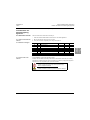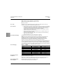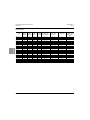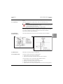
1
L-830/L-831 ADB Isolation
Transformers
User Manual
96A0438
Retain for future use.
Rev. A, 7/25/12
L-830/L-831 ADB Isolation Transformers
96A0438 Rev. A
7/25/12
Disclaimer
Disclaimer
Table of
Contents
This manual could contain technical inaccuracies or typographical errors. ADB Airfield Solutions reserves the right to
revise this manual from time to time in the contents thereof without obligation of ADB Airfield Solutions to notify any
person of such revision or change.
Details and values given in this manual have been compiled with care. They are not binding, however, and ADB
Airfield Solutions disclaims any liability for damages or detriments suffered as a result of reliance on the information
given herein or the use of products, processes or equipment to which this manual refers. No warranty is made that
the use of the information or of the products, processes or equipment to which this manual refers will not infringe any
third party's patents or rights.
Warranties
Safety
Products of ADB Airfield Solutions manufacturer are guaranteed against mechanical, electrical, and physical defects
(excluding lamps) for a period of one year from the date of installation or a maximum of 18 months from date of
shipment and are guaranteed to be merchantable and fit for the ordinary purposes for which such products are made.
ADB Airfield Solutions will correct by repair or replacement, at its option, equipment or parts which fail because of
mechanical, electrical or physical defects, provided that the goods have been properly handled and stored prior to
installation, properly installed and properly operated after installation, and provided further that Buyer gives ADB
Airfield Solutions written notice of such defects after delivery of the goods to Buyer. Refer to the Safety section for
more information on Material Handling Precautions and Storage precautions that must be followed.
ADB Airfield Solutions reserves the right to examine goods upon which a claim is made. Said goods must be
presented in the same condition as when the defect therein was discovered. ADB Airfield Solutions furthers reserves
the right to require the return of such goods to establish any claim.
ADB Airfield Solutions’ obligation under this guarantee is limited to making repair or replacement within a reasonable
time after receipt of such written notice and does not include any other costs such as the cost of removal of defective
part, installation of repaired product, labor or consequential damages of any kind, the exclusive remedy being to
require such new parts to be furnished.
ADB Airfield Solutions’ liability under no circumstances will exceed the contract price of goods claimed to be defective.
Any returns under this guarantee are to be on a transportation charges prepaid basis. For products not manufactured
by, but sold by ADB Airfield Solutions, warranty is limited to that extended by the original manufacturer.
This is ADB Airfield Solutions’ sole guarantee and warranty with respect to the goods; there are no express warranties
or warranties of fitness for any particular purpose or any implied warranties of fitness for any particular purpose or any
implied warranties other than those made expressly herein. All such warranties being expressly disclaimed.
Introduction Installation
Trademarks
General notice: other product names used here are for identification purposes only and may be trademarks of their
respective companies.
Proprietary Information
Operation
Parts
This information carrier contains proprietary information, which shall not be used for other purposes than those for
which it has been released, nor be reproduced or disclosed to third parties without the prior written consent of ADB
Airfield Solutions.
No part of this publication may be reproduced, stored in a retrieval system, or transmitted in any form or by any means,
mechanical, photocopy, recording, or otherwise, without the prior written permission of ADB Airfield Solutions. No
patent liability is assumed with respect to the use of the information contained herein. Neither is any liability assumed
for damages resulting from the use of the information contained herein.
ADB Airfield Solutions shall not be liable to the purchaser of this product or third parties for damages, losses, costs,
or expenses incurred by purchaser or third parties as a result of accident, misuse, or abuse of this product or
unauthorized modifications, repairs, or alterations to this product. ADB Airfield Solutions shall not be liable against
any damages arising from the use of any options or parts other than those designated as approved products.
Copyright © 2012 by ADB Airfield Solutions. All rights reserved.
Schematics
ii
© 2012 ADB Airfield Solutions All Rights Reserved
96A0438 Rev. A
7/25/12
L-830/L-831 ADB Isolation Transformers
Disclaimer
TABLE OF CONTENTS
L-830/L-831 ADB Isolation Transformers .................................................................... i
Table of
Contents
1.0: Safety ................................................................................................................... 1
Safety
1.1 :To use this equipment safely: .............................................................................. 1
1.1.1 :Additional Reference Materials: .................................................................. 1
1.1.2 :Qualified Personnel ..................................................................................... 1
1.1.3 :Intended Use ............................................................................................... 1
1.1.4 :Storage ........................................................................................................ 1
1.1.4.1 :Operation ............................................................................................ 2
1.1.4.2 :Material Handling Precautions ............................................................ 2
1.1.4.3 :Action in the Event of a System or Component Malfunction............... 2
1.1.4.4 :Maintenance and Repair..................................................................... 2
Installation Introduction
2.0: Isolation Transformers for Airfield Lighting Systems..................................... 3
Operation
2.1 :About this manual ................................................................................................ 3
2.1.1 :How to work with the manual ....................................................................... 3
2.1.2 :Record of changes ...................................................................................... 3
2.1.3 :Icons used in the manual ............................................................................. 3
2.2 :Introduction .......................................................................................................... 4
2.2.1 :Uses ............................................................................................................ 4
2.2.2 :Features ...................................................................................................... 4
2.2.3 :Electrical Supply .......................................................................................... 4
2.2.4 :Packaging .................................................................................................... 4
2.2.5 :Environmental Conditions ............................................................................ 4
2.2.6 :Common Order, Parts Supplied .................................................................. 4
2.2.7 :Ordering Codes ........................................................................................... 5
2.2.8 :Electrical Characteristics ............................................................................. 6
2.3 :Installation ............................................................................................................ 7
2.3.1 :Unpacking .................................................................................................... 7
2.3.2 :Installation Procedure Options .................................................................... 7
2.3.3 :Maintenance ................................................................................................ 7
2.3.4 :Troubleshooting ........................................................................................... 7
Schematics
Parts
10
© 2012 ADB Airfield Solutions All Rights Reserved
iii
L-830/L-831 ADB Isolation Transformers
96A0438 Rev. A
7/25/12
Disclaimer
Table of
Contents
Safety
Introduction Installation
Operation
Parts
Schematics
iv
© 2012 ADB Airfield Solutions All Rights Reserved
96A0438 Rev. A
7/25/12
This section contains general safety instructions for installing and using ADB Airfield Solutions equipment. Some
safety instructions may not apply to the equipment in this manual. Task- and equipment-specific warnings are
included in other sections of this manual where appropriate.
1.1 To use this
equipment safely:
Disclaimer
1.0 Safety
L-830/L-831 ADB Isolation Transformers
Safety
WARNING
•
•
•
•
•
1.1.2 Qualified Personnel
The term qualified personnel is defined here as individuals who thoroughly understand the equipment and its safe
operation, maintenance and repair. Qualified personnel are physically capable of performing the required tasks,
familiar with all relevant safety rules and regulations and have been trained to safely install, operate, maintain and
repair the equipment. It is the responsibility of the company operating this equipment to ensure that its personnel meet
these requirements.
Always use required personal protective equipment (PPE) and follow safe electrical work practices.
Safety
Installation Introduction
Safety
1.1.1 Additional Reference
Materials:
Table of
Contents
Read installation instructions in their entirety before starting installation.
• Refer to the FAA Advisory Circular AC 150/5340-26, Maintenance of Airport Visual Aids Facilities, for
instructions on safety precautions.
• Observe all safety regulations. To avoid injuries, always disconnect power before making any wiring
connections or touching any parts. Refer to FAA Advisory Circular AC 150/5340-26.
• Become familiar with the general safety instructions in this section of the manual before installing,
operating, maintaining or repairing this equipment.
• Read and carefully follow the instructions throughout this manual for performing specific tasks and
working with specific equipment.
• Make this manual available to personnel installing, operating, maintaining or repairing this equipment.
• Follow all applicable safety procedures required by your company, industry standards and government
or other regulatory agencies.
• Install all electrical connections to local code.
• Use only electrical wire of sufficient gauge and insulation to handle the rated current demand. All wiring
must meet local codes.
• Route electrical wiring along a protected path. Make sure they will not be damaged by moving
equipment.
• Protect components from damage, wear, and harsh environment conditions.
• Allow ample room for maintenance, panel accessibility, and cover removal.
• Protect components from damage, wear, and harsh environment conditions.
• Allow ample room for maintenance, panel accessibility, and cover removal.
• Protect equipment with safety devices as specified by applicable safety regulations.
• If safety devices must be removed for installation, install them immediately after the work is completed
and check them for proper functioning prior to returning power to the circuit.
Operation
NFPA 70B, Electrical Equipment Maintenance.
NFPA 70E, Electrical Safety Requirements for Employee Workplaces.
ANSI/NFPA 79, Electrical Standards for Metalworking Machine Tools.
OSHA 29 CFR, Part 1910, Occupational Health and Safety Standards.
National and local electrical codes and standards.
Parts
1.1.3 Intended Use
WARNING
Using this equipment in ways other than described in this manual may result in personal injury, death or
property and equipment damage. Use this equipment only as described in this manual.
Schematics
ADB Airfield Solutions cannot be responsible for injuries or damages resulting from nonstandard, unintended
applications of its equipment. This equipment is designed and intended only for the purpose described in this manual.
Uses not described in this manual are considered unintended uses and may result in serious personal injury, death
or property and equipment damage. Unintended uses may result from taking the following actions:
• Making changes to equipment that are not recommended or described in this manual or using parts that are not
genuine ADB Airfield Solutions replacement parts.
• Failing to make sure that auxiliary equipment complies with approval-agency requirements, local codes and all
applicable safety standards.
• Using materials or auxiliary equipment that are inappropriate or incompatible with ADB Airfield Solutions
equipment.
• Allowing unqualified personnel to perform any task.
1.1.4 Storage
CAUTION
If equipment is to be stored prior to installation, it must be protected from the weather and kept free of
condensation and dust.
Failure to follow this instruction can result in injury or equipment damage.
© 2012 ADB Airfield Solutions All Rights Reserved
1
L-830/L-831 ADB Isolation Transformers
To use this equipment safely:
96A0438 Rev. A
7/25/12
Disclaimer
1.1.4.1 Operation
WARNING
Table of
Contents
• Only qualified personnel, physically capable of operating the equipment and with no impairments in
their judgment or reaction times, should operate this equipment.
• Read all system component manuals before operating this equipment. A thorough understanding of
system components and their operation will help you operate the system safely and efficiently.
• Before starting this equipment, check all safety interlocks, fire-detection systems, and protective
devices such as panels and covers. Make sure all devices are fully functional. Do not operate the
system if these devices are not working properly. Do not deactivate or bypass automatic safety
interlocks or locked-out electrical disconnects or pneumatic valves.
• Protect equipment with safety devices as specified by applicable safety regulations.
• If safety devices must be removed for installation, install them immediately after the work is completed
and check them for proper functioning.
• Route electrical wiring along a protected path. Make sure they will not be damaged by moving
equipment.
• Never operate equipment with a known malfunction.
• Do not attempt to operate or service electrical equipment if standing water is present.
• Use this equipment only in the environments for which it is rated. Do not operate this equipment in
humid, flammable, or explosive environments unless it has been rated for safe operation in these
environments.
• Never touch exposed electrical connections on equipment while the power is ON.
Safety
Introduction Installation
To use this
equipment
safely:
1.1.4.2 Material Handling
Precautions
CAUTION
This equipment may contain electrostatic sensitive devices.
• Protect from electrostatic discharge.
• Electronic modules and components should be touched only when this is unavoidable e.g. soldering,
replacement.
• Before touching any component of the cabinet you should bring your body to the same potential as the
cabinet by touching a conductive earthed part of the cabinet.
• Electronic modules or components must not be brought in contact with highly insulating materials such
as plastic sheets, synthetic fiber clothing. They must be laid down on conductive surfaces.
• The tip of the soldering iron must be grounded.
• Electronic modules and components must be stored and transported in conductive packing.
Operation
1.1.4.3 Action in the Event of a
System or Component
Malfunction
WARNING
• Do not operate a system that contains malfunctioning components. If a component malfunctions, turn
the system OFF immediately.
• Disconnect and lock out electrical power.
• Allow only qualified personnel to make repairs. Repair or replace the malfunctioning component
according to instructions provided in its manual.
Parts
1.1.4.4 Maintenance and Repair
WARNING
Schematics
Allow only qualified personnel to perform maintenance, troubleshooting, and repair tasks.
• Only persons who are properly trained and familiar with ADB Airfield Solutions equipment are permitted
to service this equipment.
• Disconnect and lock out electrical power.
• Always use safety devices when working on this equipment.
• Follow the recommended maintenance procedures in the product manuals.
• Do not service or adjust any equipment unless another person trained in first aid and CPR is present.
• Connect all disconnected equipment ground cables and wires after servicing equipment. Ground all
conductive equipment.
• Use only approved ADB Airfield Solutions replacement parts. Using unapproved parts or making
unapproved modifications to equipment may void agency approvals and create safety hazards.
• Check interlock systems periodically to ensure their effectiveness.
• Do not attempt to service electrical equipment if standing water is present. Use caution when servicing
electrical equipment in a high-humidity environment.
• Use tools with insulated handles when working with electrical equipment.
2
© 2012 ADB Airfield Solutions All Rights Reserved
L-830/L-831 ADB Isolation Transformers
Isolation Transformers for Airfield Lighting Systems
This manual covers all information pertaining to the ADB Airfield Isolation Transformers.
2.1 About this manual
The manual shows the information necessary to:
•
2.1.1 How to work with the
manual
Table of
Contents
2.0 Isolation
Transformers for
Airfield Lighting
Systems
Disclaimer
96A0438 Rev. A
7/25/12
Install and maintain ADB Isolation Transformers in an airfield application.
1. Become familiar with the structure and content.
2. Carry out the actions completely and in the given sequence.
Rev
All
A
Description
Checked
Approved
Date
Released Manual
For all WARNING symbols see the Safety section.
Carefully read and observe all safety instructions in this manual, which alert you to safety
hazards and conditions that may result in personal injury, death or property and equipment
damage and are accompanied by the symbol shown below.
Operation
2.1.3 Icons used in the
manual
Installation
Isolation
Transformers for Airfield
Page
Safety
2.1.2 Record of changes
WARNING
• Failure to observe a warning may result in personal injury,
death or equipment damage.
Parts
CAUTION
Schematics
• Failure to observe a caution may result in equipment damage.
© 2012 ADB Airfield Solutions All Rights Reserved
3
L-830/L-831 ADB Isolation Transformers
Introduction
Disclaimer
2.2 Introduction
96A0438 Rev. A
7/25/12
Compliance with Standards
FAA: L-830 and L-831 AC 150/5345-47 (Current Edition)
ICAO: Aerodrome Design Manual, Part 5 para. 3.2.1.7a
MIL: MIL-T-27535A
Table of
Contents
2.2.1 Uses
2.2.2 Features
Designed for use in airfield lighting systems to isolate low-voltage lamps from the high
operating voltages present on airfield series lighting circuits.
— Quick and easy connection by means of factory-molded L-823 plugs and receptacles.
— Two single-conductor primary cables (8 AWG, 5,000 V) with a molded Style 2 plug on
one lead and a molded Style 9 receptacle on the other lead; one two-conductor
secondary cable (12 AWG 600 V) with Style 8 two-pin receptacle
Safety
— Complete water tightness–Cables are an integral part of the transformer and their
sheath is molded in the transformer body
Introduction Installation
— The outer molded jacket is acid-, alkali-, and oil-resistant and also resists deicing
fluids, ozone, and UV radiation
— May be buried directly in the ground, exposed to the sun, immersed in water, and
exposed to other weather elements
— Ambient temperature: -67 °F to +149 °F (-55 °C to +65 °C)
2.2.3 Electrical Supply
Operates at 60 Hz (L-830) on series circuits rated up to 5,000 VAC.
NOTE: The primary windings of the transformer are connected in a 6.6 A series circuit
supplied by a constant current regulator. The continuity of the series lighting loop is
maintained even if one or more lamps supplied by individual isolation transformer
secondaries are open-circuited due to lamp failures. In addition, there is a complete
separation of the high-voltage primary and low-voltage secondary windings.
Operation
Series circuit components and connectors must be installed per the recommendations shown
in FAA AC 150/5340-30 (latest revision). There are many installation variables outside the
control of ADB that may affect the overall circuit insulation resistance. ADB Airfield Solutions
is not responsible for series circuit insulation resistance requirements above the limits defined
in FAA AC 150/5340-30 or AC 150/5340-26 (latest revisions).
2.2.4 Packaging
Table 1:
Weight
Style
Parts
Schematics
2.2.5 Environmental
Conditions
Part No.
Avg. Weight - lb (kg)
L-830-16
1ST010666010
2.6 (1.2)
L-830-17
1ST020666010
2.8 (1.3)
L-830-1
1ST045666010
3.0 (1.4)
L-830-3
1ST065666010
4.8 (2.2)
L-830-4
1ST100666010
5.9 (2.7)
L-830-18
1ST150666010
7.4 (3.4)
L-830-6
1ST200666010
9.5 (4.3)
L-830-10
1ST300666010
11.8 (5.4)
L-830-14
1ST500666010
16.5 (7.5)
ADB Isolation Transformers are constructed for continuous outdoor service at temperatures
from -67° F to 149° F (-55° to + 65° C).
ADB Isolation Transformers operate as designed buried in the ground and submerged in
water with up to 5,000 Volts potential between the primary windings and ground.
2.2.6 Common Order,
Parts Supplied
4
L830/L831 Isolation Transformer (see ordering codes)
Heat Shrinkable Airfield Lighting Kit (as required)
© 2012 ADB Airfield Solutions All Rights Reserved
96A0438 Rev. A
7/25/12
L-830/L-831 ADB Isolation Transformers
Introduction
Ordering Code
Disclaimer
2.2.7 Ordering Codes
1STXXXXXXX10
Safety
Table of
Contents
Power Range
010 = 10/15 W (L-830-16)
020 = 20/25 W (L-830-17)
045 = 45 W (L-830-1)
065 = 65 W (L-830-3)
100 = 100 W (L-830-4)
150 = 150 W (L-830-18)
200 = 200 W (L-830-6)
300 = 300 W (L-830-10)
500 = 500 W (L-830-14)
Primary Current
6 = 6.6 A
Installation Introduction
Secondary Current
6 = 6.6 A
Frequency
6 = 60 Hz
Grounding Connection
0 = Without ground
Ordering Code
FAA
Style
Rated
Watts
Prim.
Sec.
Hz
Amps Amps
L-830-16
10/15
60
6.6
6.6
1ST010666010
L-830-17
20/25
60
6.6
6.6
1ST020666010
L-830-1
30/45
60
6.6
L-830-3
65
60
6.6
6.6
1ST065666010
L-830-4
100
60
6.6
6.6
1ST100666010
L-830-18
150
60
6.6
6.6
1ST150666010
L-830-6
200
60
6.6
6.6
1ST200666010
L-830-10
300
60
6.6
6.6
1ST300666010
L-830-14
500
60
6.6
6.6
1ST500666010
Operation
Parts
1ST045666010
Schematics
6.6
Part No.
© 2012 ADB Airfield Solutions All Rights Reserved
5
L-830/L-831 ADB Isolation Transformers
Introduction
Disclaimer
2.2.8 Electrical
Characteristics
Type
96A0438 Rev. A
7/25/12
ADB Isolation Transformer characteristics are documented in table 2.
Wattage
(Watts)
Primary
Amperes
Minimum Minimum
Power Efficiency
(percent)
Factor
Secondary Full
Load Amperes
Secondary ShortCircuited
Amperes
Load Ohms
Table of
Contents
Secondary
Maximum OpenCircuit Voltage RMS
L830-1
30/45
6.6
0.95
80
6.53 - 6.67
6.6 - 7.1
1.15
25
L830-2
30/45
20.0
0.95
80
6.53 - 6.67
6.6 - 7.1
1.15
25
Safety
Introduction Installation
L830-3
65
6.6
0.95
80
6.53 - 6.67
6.6 - 7.1
1.60
30
L830-4
100
6.6
0.95
85
6.53 - 6.67
6.6 - 7.1
2.44
70
L830-5
100
20.0
0.95
85
6.53 - 6.67
6.6 - 7.1
2.44
70
L830-6
200
6.6
0.95
90
6.53 - 6.67
6.6 - 7.1
4.82
100
L830-7
200
20.0
0.95
90
6.53 - 6.67
6.6 - 7.1
4.82
100
L830-8
300
6.6
0.95
90
19.8 - 20.2
20.0 - 22.0
0.90
70
L830-9
300
20.0
0.95
90
19.8 - 20.2
20.0 - 22.0
0.90
70
L830-10
300
6.6
0.95
90
6.53 - 6.67
6.6 - 7.1
8.25
135
L830-11
300
20.0
0.95
90
6.53 - 6.67
6.6 - 7.1
8.25
135
L830-12
500
6.6
0.95
90
19.8 - 20.2
20.0 - 22.0
1.35
70
L830-13
500
20.0
0.95
90
19.8 - 20.2
20.0 - 22.0
1.35
70
L830-14
500
6.6
0.95
90
6.53 - 6.67
6.6 - 7.1
12.0
230
L830-15
500
20.0
0.95
90
6.53 - 6.67
6.6 - 7.1
12.0
230
L830-16
10/15
6.6
0.95
70
6.53 - 6.67
6.6 - 7.1
0.34
8.0
L830-17
20/25
6.6
0.95
70
6.53 - 6.67
6.6 - 7.1
0.57
8.0
L830-18
150
6.6
0.95
85
6.53 - 6.67
6.6 - 7.1
3.58
70
L830-19
150
20.0
0.95
85
19.8 - 20.2
20.0 - 22.0
3.58
70
Operation
Parts
Schematics
6
© 2012 ADB Airfield Solutions All Rights Reserved
L-830/L-831 ADB Isolation Transformers
Installation
2.3 Installation
L-830/L-831 ADB airfield isolation transformers installation procedures are covered in this
section.
2.3.1 Unpacking
The isolation transformers are shipped ready to install in the airfield series circuit.
Disclaimer
96A0438 Rev. A
7/25/12
WARNING
Table of
Contents
Read installation instructions in their entirety before starting installation.
• Do not install a damaged isolation transformer in any circuit.
• Do not disconnect an isolation transformer from an operating series circuit! Extreme voltages will result
along with a possibility of an arc flash explosion.
Failure to follow this instruction can result in injury or equipment damage.
Safety
Inspect the isolation transformer prior to installation. Look for cracks and cuts in the cables.
If you note any damage to any equipment, file a claim with the carrier immediately.
The following diagrams show the two main option for isolation transformer installation.
Operation
Installation
2.3.2 Installation
Procedure Options
Installation
The carrier may need to inspect the equipment.
Parts
Deep Base Application
2.3.3 Maintenance
ADB Isolation Transformers require no maintenance.
2.3.4 Troubleshooting
To inspect an isolation transformer for possible damage.
Schematics
Stake Mount Application
1. Tagout/Lockout the circuit using local procedures.
2. Inspect the entire assembly if an isolation transformer fault is suspected.
To test a secondary circuit on a live airfield, USE EXTREME CAUTION.
1. Tagout/Lockout the circuit using local procedures.
2. Place the current testing device around the secondary wire.
3. Energize the circuit and note the secondary current.
4. Tagout/Lockout the circuit using local procedures and remove current testing equipment.
© 2012 ADB Airfield Solutions All Rights Reserved
7
L-830/L-831 ADB Isolation Transformers
Installation
96A0438 Rev. A
7/25/12
Disclaimer
Table of
Contents
Safety
Installation
Installation
Operation
Parts
Schematics
8
© 2012 ADB Airfield Solutions All Rights Reserved
L-830/L-831 ADB Isolation Transformers
User Manual
Registered office:
France
ADB Airfield Solutions LLC
Phone: +33 (1) 4922 9250
ADB
Fax: +33 (1) 4922 9255
Unit 44, Business Innovation Centre
977 Gahanna Parkway
Binley Business Park
Columbus, OH 43230
ADB Airfield Solutions GmbH & Co. KG
Harry Weston Road
USA
Von-der-Tannstr. 31
Coventry, CV3 2TX
Phone: +1 (614) 8611 304
90439 Nürnberg
United kingdom
Fax: +1 (614) 8642 069
Germany
Phone: +44 (0)1455 883130
Phone: +49 (911) 9239 1287
Fax: +44 (0)1455 883179
Fax:+49 (911) 2852 582
Other addresses:
ADB
ADB N.V.
Airfield Solutions
ADB Airfield Solutions Ltd.
Asia Pacific Regional HQ
Leuvensesteenweg 585
5500 North Service Road, Suite 1108
Unit C-9.3.1, Level 9, Block C
B-1930 Zaventem
Burlington, Ontario L7L 6W6
Mines Waterfront Business Park
Belgium
Canada
No. 3, Jalan Tasik
Phone: +32 (2) 722 17 11
Phone: +1 (905) 331 6887
The Mines Resort City
Fax: +32 (2) 722 17 64
Fax: +1 (905) 331 9389
43300 Seri Kembangan Selangor
[email protected]
Malaysia
www.adb-air.com
ADB Airfield Technologies Ltd.
Phone: +603 8941 4868
01A Unit, 9F, LSH Plaza
Fax: +603 8942 4869
8, Wangjing Jie
Chaoyang District
Beijing 100102
ADB Airfield Solutions Netherlands
P.R. China
Prinses Beatrixlaan 614
Phone: +86 10 8476 0106
Office D3.14
Fax: +86 10 8476 0090
2595 BM Den Haag
The Netherlands
ADB N.V.
Phone: +31 (0)70 304 3611
Dubai Silicon Oasis
Fax: +31 (0)70 333 8094
Wing D - Office D-309
P.O. Box 341218
ADB Airfield Solutions, Ltd.
United Arab Emirates
2nd Floor, 3 Rivonia Village
Phone: + 971 4372 4970
Cnr Mutual Road and Rivonia Boulevard
Fax: + 971 4372 4975
South
Rivonia 2128
ADB N.V./S.A.
South Africa
39/47 Boulevard Ornano
Phone: +27 (11)234 6768
93200 Saint-Denis
Fax: +27 (11)234 6739
ADB Airfield
Solutions USA
977 Gahanna Pkwy
Columbus, Ohio 43230 USA
Telephone: (+1 614-861-1304)
Fax: +1 614-864-2069
www.adb-airfi eldsolutions.com
The information contained in this document is subject to change without notice. ADB reserves the
right to make changes and improvements to its products and assumes no responsibility for making
these modifications on any equipment previously sold.
96A0438 © 2012 ADB Airfield Solutions All Rights Reserved