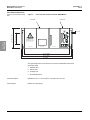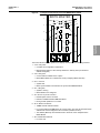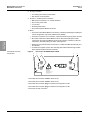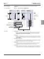
1
BRITE III Master Control
Device
Installation Manual
96A0428
Retain for future use.
Rev. C, 6/27/11
Compliance with Standards
FAA: Approved for use with SMGCS systems.
This includes both Stop Bar and Runway Guard
Light control/monitoring according to
AC 150/5340-30 (Current Edition);
manufactured to AC 120-57 (Current Edition).
ICAO: Complies with CAT I/II/III ICAO lamp
supervision requirements. Supports A-SMGCS
for enhanced aircraft guidance in all weather
conditions to prevent aircraft collisions and
runway incursions.
BRITE III Master Control Device
96A0428 Rev. C
6/27/11
Disclaimer
Disclaimer
Table of
Contents
This manual could contain technical inaccuracies or typographical errors. ADB Airfield Solutions reserves the right to
revise this manual from time to time in the contents thereof without obligation of ADB Airfield Solutions to notify any
person of such revision or change.
Details and values given in this manual have been compiled with care. They are not binding, however, and ADB
Airfield Solutions disclaims any liability for damages or detriments suffered as a result of reliance on the information
given herein or the use of products, processes or equipment to which this manual refers. No warranty is made that
the use of the information or of the products, processes or equipment to which this manual refers will not infringe any
third party's patents or rights.
Warranties
Safety
Products of ADB Airfield Solutions manufacturer are guaranteed against mechanical, electrical, and physical defects
(excluding lamps) for a period of one year from the date of installation or a maximum of 18 months from date of
shipment and are guaranteed to be merchantable and fit for the ordinary purposes for which such products are made.
ADB Airfield Solutions will correct by repair or replacement, at its option, equipment or parts which fail because of
mechanical, electrical or physical defects, provided that the goods have been properly handled and stored prior to
installation, properly installed and properly operated after installation, and provided further that Buyer gives ADB
Airfield Solutions written notice of such defects after delivery of the goods to Buyer. Refer to the Safety section for
more information on Material Handling Precautions and Storage precautions that must be followed.
ADB Airfield Solutions reserves the right to examine goods upon which a claim is made. Said goods must be
presented in the same condition as when the defect therein was discovered. ADB Airfield Solutions furthers reserves
the right to require the return of such goods to establish any claim.
ADB Airfield Solutions’ obligation under this guarantee is limited to making repair or replacement within a reasonable
time after receipt of such written notice and does not include any other costs such as the cost of removal of defective
part, installation of repaired product, labor or consequential damages of any kind, the exclusive remedy being to
require such new parts to be furnished.
ADB Airfield Solutions’ liability under no circumstances will exceed the contract price of goods claimed to be defective.
Any returns under this guarantee are to be on a transportation charges prepaid basis. For products not manufactured
by, but sold by ADB Airfield Solutions, warranty is limited to that extended by the original manufacturer.
This is ADB Airfield Solutions’ sole guarantee and warranty with respect to the goods; there are no express warranties
or warranties of fitness for any particular purpose or any implied warranties of fitness for any particular purpose or any
implied warranties other than those made expressly herein. All such warranties being expressly disclaimed.
Introduction Installation
Trademarks
General notice: other product names used here are for identification purposes only and may be trademarks of their
respective companies.
Proprietary Information
Operation
Parts
This information carrier contains proprietary information, which shall not be used for other purposes than those for
which it has been released, nor be reproduced or disclosed to third parties without the prior written consent of ADB
Airfield Solutions.
No part of this publication may be reproduced, stored in a retrieval system, or transmitted in any form or by any means,
mechanical, photocopy, recording, or otherwise, without the prior written permission of ADB Airfield Solutions. No
patent liability is assumed with respect to the use of the information contained herein. Neither is any liability assumed
for damages resulting from the use of the information contained herein.
ADB Airfield Solutions shall not be liable to the purchaser of this product or third parties for damages, losses, costs,
or expenses incurred by purchaser or third parties as a result of accident, misuse, or abuse of this product or
unauthorized modifications, repairs, or alterations to this product. ADB Airfield Solutions shall not be liable against
any damages arising from the use of any options or parts other than those designated as approved products.
Copyright © 2010 by ADB Airfield Solutions. All rights reserved.
Schematics
ii
© 2010 ADB Airfield Solutions All Rights Reserved
Abbreviation for Constant Current Regulator. The CCRs are located within the
Airfield Lighting Vault (ALV). They produce a constant current output to the
airfield series circuit that light the airfield lighting fixtures.
BRITE™
ADB Airfield Solutions’ trademarked abbreviation for Bi-directional Series
Transceiver which is a term that describes the technology used to transmit and
receive data across airfield lighting series circuit cabling.
Remote
Unit installed in the airfield (normally in pull-pits or base cans) which provides
control and monitoring of individual or blocks of light fixtures. Each Remote has
its own unique address for control and monitoring data communication to the
Master.
Master
Unit installed within the lighting vault that provides the means for data
communication on the airfield series circuit cables. The Master is connected in
parallel (across) to the output of the CCR. Each series circuit that contains
Remotes must also have a Master installed at the CCR.
MWD
Abbreviation of Microwave Detector. Microwave detectors are installed in predesignated locations on the airfield. The MWD also has its own unique address
for control and monitoring purposes. A MWD is used to detect movement within
an established detection zone and communicate the status back to the Master.
Control Panel
This term is used to reference the device used to control and monitor the
controllable stopbars and the associated lighting equipment. The control panel
could be either an L-821 style pushbutton panel or a Touchscreen style control
panel. The control panel is located in the Air Traffic Control Tower cab.
SMGCS
Acronym which means Surface Movement Guidance and Control System.
SMGCS is an organized system created to improve and enhance low visibility
operations.
VSP
Acronym for Variable System Parameter. This term relates to a time value (in
seconds) determined by the airport that is used in conjunction with the Stopbar
control timing. In the event that the automatic Stopbar control or MWDs fail, the
Stopbars are reset after the VSP value has expired.
Acronyms
CCR
Table of
Contents
Acronym for Airfield Lighting Computer Monitoring System. An ALCMS
incorporates many components that are used to control and monitor an airport’s
entire airfield lighting system. The ALCMS may include Touch Screens for
lighting control, Maintenance Center(s) for data viewing and archiving, Electrical
Lighting equipment for CCR control and monitoring.
Safety
ALCMS
Installation Introduction
General Aviation Terms and Acronyms that you may encounter using our manuals.
Schematics
Parts
a.0 Terms and
Acronyms
BRITE III Master Control Device
Operation
96A0428 Rev. C
6/27/11
© 2010 ADB Airfield Solutions All Rights Reserved
iii
BRITE III Master Control Device
96A0428 Rev. C
6/27/11
Acronyms
Table of
Contents
Safety
Introduction Installation
Operation
Parts
Schematics
iv
© 2010 ADB Airfield Solutions All Rights Reserved
96A0428 Rev. C
6/27/11
BRITE III Master Control Device
TOC
Disclaimer
TABLE OF CONTENTS
BRITE III Master Control Device ...................................................................................................i
Table of
Contents
a.0: Terms and Acronyms ........................................................................................ III
1.0: Safety ................................................................................................................... 1
Installation Introduction
TOC
Safety
1.1 :To use this equipment: ......................................................................................... 1
1.1.1 :Additional Reference Materials: .................................................................. 1
1.1.2 :Qualified Personnel ..................................................................................... 1
1.1.3 :Intended Use ............................................................................................... 1
1.1.4 :Storage ........................................................................................................ 1
1.1.4.1 :Operation ............................................................................................ 2
1.1.4.2 :Material Handling Precautions ............................................................ 2
1.1.4.3 :Action in the Event of a System or Component Malfunction............... 2
1.1.4.4 :Maintenance and Repair..................................................................... 2
1.1.4.5 :Operation of Overloaded Regulators .................................................. 2
2.0: BRITE III Master................................................................................................... 3
© 2010 ADB Airfield Solutions All Rights Reserved
Schematics
Parts
Operation
2.1 :Manual Introduction .............................................................................................. 3
2.1.1 :How to work with the manual ....................................................................... 3
2.1.2 :Record of changes ...................................................................................... 3
2.1.3 :Icons used in the manual ............................................................................. 3
2.2 :BRITE Master Introduction ................................................................................... 4
2.2.1 :Compliance with Standards ......................................................................... 4
2.2.2 :Uses ............................................................................................................ 4
2.2.3 :Illustration .................................................................................................... 4
2.2.4 :Checking the Device .................................................................................... 5
2.2.4.1 :Scope of Supply.................................................................................. 5
2.2.4.2 :Unpacking ........................................................................................... 5
2.2.4.3 :Inspection ........................................................................................... 5
2.2.5 :Storage ........................................................................................................ 5
2.2.6 :Views of the Device ..................................................................................... 6
2.2.6.1 :Front View with Control Unit ............................................................... 6
2.2.6.2 :Dimensions ......................................................................................... 6
2.2.6.3 :Weight................................................................................................. 6
2.2.6.4 :Rear View with Connections ............................................................... 8
2.2.7 :Construction ................................................................................................ 9
2.2.7.1 :Block Diagram .................................................................................... 9
2.2.7.2 :Units.................................................................................................... 9
2.3 :Theory of Operation .......................................................................................... 10
2.3.0.1 :Architecture....................................................................................... 10
2.4 :Installation of stand-alone BRITE Masters ......................................................... 11
2.4.1 :Installation in the Control Cabinet .............................................................. 11
2.4.1.1 :Power Supply.................................................................................... 11
2.4.1.2 :Connection to the Series Circuit ....................................................... 11
2.4.2 :Connection to the Ethernet Network .......................................................... 12
2.4.3 :Earth Grounding ........................................................................................ 12
2.4.4 :Safety Instructions ..................................................................................... 13
2.5 :Replacing a stand-alone BRITE Master ............................................................. 14
2.5.1 :Replacement of Units ................................................................................ 14
2.5.1.1 :Replacing a High-Voltage Unit.......................................................... 14
2.5.1.2 :Replacing the Control Unit ................................................................ 15
2.6 :Troubleshooting and Fault Correction ................................................................ 16
2.7 :Modes of Operation ............................................................................................ 17
2.7.1 :State on Delivery ....................................................................................... 17
2.7.1.1 :Base State ........................................................................................ 17
v
BRITE III Master Control Device
TOC
96A0428 Rev. C
6/27/11
Disclaimer
2.7.1.2 :Maintenance Mode............................................................................ 17
2.7.1.3 :Operating Mode ................................................................................ 17
2.8 :Technical Specifications .....................................................................................18
2.8.1 :Environmental Conditions ..........................................................................18
2.8.1.1 :System Specifications ....................................................................... 19
2.9 :Accessories and Spare Parts .............................................................................20
2.9.1 :Ordering Code ...........................................................................................20
Table of
Contents
Document Date (12/2010)
22
Safety
Introduction Installation
TOC
Operation
Parts
Schematics
vi
© 2010 ADB Airfield Solutions All Rights Reserved
96A0428 Rev. C
6/27/11
This section contains general safety instructions for installing and using ADB Airfield Solutions equipment. Some
safety instructions may not apply to the equipment in this manual. Task- and equipment-specific warnings are
included in other sections of this manual where appropriate.
1.1 To use this
equipment:
Disclaimer
1.0 Safety
BRITE III Master Control Device
Safety
WARNING
1.1.2 Qualified Personnel
Safety
Installation Introduction
Safety
•
•
•
•
•
NFPA 70B, Electrical Equipment Maintenance.
NFPA 70E, Electrical Safety Requirements for Employee Workplaces.
ANSI/NFPA 79, Electrical Standards for Metalworking Machine Tools.
OSHA 29 CFR, Part 1910, Occupational Health and Safety Standards.
National and local electrical codes and standards.
Operation
1.1.1 Additional Reference
Materials:
Table of
Contents
Read installation instructions in their entirety before starting installation.
• Refer to the FAA Advisory Circular AC 150/5340-26, Maintenance of Airport Visual Aids Facilities, for
instructions on safety precautions.
• Observe all safety regulations. To avoid injuries, always disconnect power before making any wiring
connections or touching any parts. Refer to FAA Advisory Circular AC 150/5340-26.
• Become familiar with the general safety instructions in this section of the manual before installing,
operating, maintaining or repairing this equipment.
• Read and carefully follow the instructions throughout this manual for performing specific tasks and
working with specific equipment.
• Make this manual available to personnel installing, operating, maintaining or repairing this equipment.
• Follow all applicable safety procedures required by your company, industry standards and government
or other regulatory agencies.
• Install all electrical connections to local code.
• Use only electrical wire of sufficient gauge and insulation to handle the rated current demand. All wiring
must meet local codes.
• Route electrical wiring along a protected path. Make sure they will not be damaged by moving
equipment.
• Protect components from damage, wear, and harsh environment conditions.
• Allow ample room for maintenance, panel accessibility, and cover removal.
• Protect components from damage, wear, and harsh environment conditions.
• Allow ample room for maintenance, panel accessibility, and cover removal.
• Protect equipment with safety devices as specified by applicable safety regulations.
• If safety devices must be removed for installation, install them immediately after the work is completed
and check them for proper functioning prior to returning power to the circuit.
The term qualified personnel is defined here as individuals who thoroughly understand the equipment and its safe
operation, maintenance and repair. Qualified personnel are physically capable of performing the required tasks,
familiar with all relevant safety rules and regulations and have been trained to safely install, operate, maintain and
repair the equipment. It is the responsibility of the company operating this equipment to ensure that its personnel meet
these requirements.
Always use required personal protective equipment (PPE) and follow safe electrical work practices.
Parts
1.1.3 Intended Use
WARNING
Using this equipment in ways other than described in this manual may result in personal injury, death or
property and equipment damage. Use this equipment only as described in this manual.
Schematics
ADB Airfield Solutions cannot be responsible for injuries or damages resulting from nonstandard, unintended
applications of its equipment. This equipment is designed and intended only for the purpose described in this manual.
Uses not described in this manual are considered unintended uses and may result in serious personal injury, death
or property and equipment damage. Unintended uses may result from taking the following actions:
• Making changes to equipment that are not recommended or described in this manual or using parts that are not
genuine ADB Airfield Solutions replacement parts.
• Failing to make sure that auxiliary equipment complies with approval-agency requirements, local codes and all
applicable safety standards.
• Using materials or auxiliary equipment that are inappropriate or incompatible with ADB Airfield Solutions
equipment.
• Allowing unqualified personnel to perform any task.
1.1.4 Storage
CAUTION
If equipment is to be stored prior to installation, it must be protected from the weather and kept free of
condensation and dust.
Failure to follow this instruction can result in injury or equipment damage.
© 2010 ADB Airfield Solutions All Rights Reserved
1
BRITE III Master Control Device
To use this equipment:
96A0428 Rev. C
6/27/11
Disclaimer
1.1.4.1 Operation
WARNING
Table of
Contents
• Only qualified personnel, physically capable of operating the equipment and with no impairments in
their judgment or reaction times, should operate this equipment.
• Read all system component manuals before operating this equipment. A thorough understanding of
system components and their operation will help you operate the system safely and efficiently.
• Before starting this equipment, check all safety interlocks, fire-detection systems, and protective
devices such as panels and covers. Make sure all devices are fully functional. Do not operate the
system if these devices are not working properly. Do not deactivate or bypass automatic safety
interlocks or locked-out electrical disconnects or pneumatic valves.
• Protect equipment with safety devices as specified by applicable safety regulations.
• If safety devices must be removed for installation, install them immediately after the work is completed
and check them for proper functioning.
• Route electrical wiring along a protected path. Make sure they will not be damaged by moving
equipment.
• Never operate equipment with a known malfunction.
• Do not attempt to operate or service electrical equipment if standing water is present.
• Use this equipment only in the environments for which it is rated. Do not operate this equipment in
humid, flammable, or explosive environments unless it has been rated for safe operation in these
environments.
• Never touch exposed electrical connections on equipment while the power is ON.
Safety
Introduction Installation
To use this
equipment:
1.1.4.2 Material Handling
Precautions
CAUTION
This equipment may contain electrostatic sensitive devices.
• Protect from electrostatic discharge.
• Electronic modules and components should be touched only when this is unavoidable e.g. soldering,
replacement.
• Before touching any component of the cabinet you should bring your body to the same potential as the
cabinet by touching a conductive earthed part of the cabinet.
• Electronic modules or components must not be brought in contact with highly insulating materials such
as plastic sheets, synthetic fiber clothing. They must be laid down on conductive surfaces.
• The tip of the soldering iron must be grounded.
• Electronic modules and components must be stored and transported in conductive packing.
Operation
1.1.4.3 Action in the Event of a
System or Component
Malfunction
WARNING
• Do not operate a system that contains malfunctioning components. If a component malfunctions, turn
the system OFF immediately.
• Disconnect and lock out electrical power.
• Allow only qualified personnel to make repairs. Repair or replace the malfunctioning component
according to instructions provided in its manual.
Parts
1.1.4.4 Maintenance and Repair
WARNING
Schematics
Allow only qualified personnel to perform maintenance, troubleshooting, and repair tasks.
• Only persons who are properly trained and familiar with ADB Airfield Solutions equipment are permitted
to service this equipment.
• Disconnect and lock out electrical power.
• Always use safety devices when working on this equipment.
• Follow the recommended maintenance procedures in the product manuals.
• Do not service or adjust any equipment unless another person trained in first aid and CPR is present.
• Connect all disconnected equipment ground cables and wires after servicing equipment. Ground all
conductive equipment.
• Use only approved ADB Airfield Solutions replacement parts. Using unapproved parts or making
unapproved modifications to equipment may void agency approvals and create safety hazards.
• Check interlock systems periodically to ensure their effectiveness.
• Do not attempt to service electrical equipment if standing water is present. Use caution when servicing
electrical equipment in a high-humidity environment.
• Use tools with insulated handles when working with electrical equipment.
1.1.4.5 Operation of
Overloaded Regulators
WARNING
• Operation of a Regulator while overloaded at any step may result in equipment failure or equipment
damage.
2
© 2010 ADB Airfield Solutions All Rights Reserved
The BRITE III Master is a key subsystem in various Airfield Ground Lighting Automation
Systems. ADB’s BRITE III system is the latest state-of-the art individual airfield light control
and monitoring system. BRITE III provides a radical leap in performance over prior airfield
power line carrier systems. This system is designed to communicate on the existing airfi eld
series circuit power line without requiring separate dedicated cabling. This system has
patents pending in many countries around the world.
Disclaimer
2.0 BRITE III
Master
BRITE III Master Control Device
Manual Introduction
Proprietary Information
General notice: other product names used here are for identification purposes only and may
be trademarks of their respective companies.
Table of
Contents
96A0428 Rev. C
6/27/11
2.1 Manual
Introduction
This document provides a manual on installation of Bi-Directional Series Transeiver (BRITE)
Master.
In the following chapters, detailed information about commissioning, replacing and
maintaining BRITE Master is presented.
1. Be familiar with the structure and content.
Manual
Introduction
2.1.1 How to work with the
manual
2. Carry out the actions completely and in the given sequence.
2.1.2 Record of changes
Rev
Description
Checked
4.1
New
Geert Bollens
4.2
Updated safety information
Geert Bollens
22.04.10
C
Updated all for US market
RH
4/6/11
Approved
Date
23.12.09
Operation
All
Installation
Page
Safety
AGLAS™ is a registered trademark of ADB and is known as BRITE III in the US market.
For all WARNING symbols see the Safety section.
Carefully read and observe all safety instructions in this manual, which alert you to safety
hazards and conditions that may result in personal injury, death or property and equipment
damage and are accompanied by the symbol shown below.
Parts
2.1.3 Icons used in the
manual
Schematics
WARNING
• Failure to observe a warning may result in personal injury,
death or equipment damage.
CAUTION
• Failure to observe a caution may result in equipment damage.
© 2010 ADB Airfield Solutions All Rights Reserved
3
BRITE III Master Control Device
BRITE Master Introduction
Disclaimer
2.2 BRITE Master
Introduction
96A0428 Rev. C
6/27/11
The BRITE Master is avaible as a standard 4U 19” rack component, located above/close to
the CCR (Constant Current Regulator), or as an integrated unit, built inside the CCR.
Maximum power rating is 30kVA at max. 6.6A RMS.
2.2.1 Compliance with
Standards
FAA: Approved for use with SMGCS systems. This includes both Stop Bar and Runway
Guard Light control/monitoring according to AC 150/5340-30 (Current Edition); manufactured
to AC 120-57 (Current Edition).
Table of
Contents
ICAO: Complies with CAT I/II/III ICAO lamp supervision requirements. Supports A-SMGCS
for enhanced aircraft guidance in all weather conditions to prevent aircraft collisions and
runway incursions.
2.2.2 Uses
•
BRITE III provides distributed intelligence in the airfield to control and monitor a variety of
airfield lighting devices. It can be used in the following applications:
Safety
— Stop bar control and monitoring
— Elevated and in-pavement Runway Guard Light (RGL) control and monitoring
— Interface with aircraft/vehicle presence sensors (option)
— FAA Runway Status Light (RWSL) systems
BRITE Master
Introduction
— As a key component in a Surface Movement Guidance Control System (SMGCS)
— Failed-lamp detection and location identifi cation
— Selective control and monitoring of various airfield lighting devices
Installation
•
BRITE III provides relevant information concerning the status of various airfield lighting
devices to both maintenance and airport control tower personnel.
•
The BRITE III can also be used to:
— Support optimization of traffic volume, flexibility, and air side safety.
— Meet stringent command timing requirements while ensuring elimination of
interference on FAA RWSL applications.
Operation
— Ensure reliable Stop Bar guidance for aircraft on the ground during CAT III conditions,
increasing safety and reducing the risk of runway incursions.
— Automatically detects and reports lamp failure location, decreasing downtime and
maintenance costs.
2.2.3 Illustration
Figure 1:
BRITE Master front view
BRITE MASTER
Parts
Connect
Error
CCR
X4
Sync
X9
ETH-0
Run
X3
Power
Forward
CAPACITOR UNIT
4
INDUCTOR UNIT
COUPLING UNIT
X10
ETH-1
X12
RS232-1
X7
Current Sense
- Read instruction manual
- Risk of electric shock and electrical energy
High voltage levels
Capacitor stores hazardous energy
Do not remove cover until 5 minutes after
disconnecting all sources of energy
X11
RS232-2
X2
Coupling / Supply
X1
Coupling
Schematics
CAUTION
X6
RS485-1
X5
RS485-0
Reset
X8
Power
Supply
F1
Fuse
T2A
S2
Power
Switch
CONTROLLER / PROTECTION UNIT
© 2010 ADB Airfield Solutions All Rights Reserved
96A0428 Rev. C
6/27/11
BRITE III Master Control Device
BRITE Master Introduction
2.2.4.2 Unpacking
The device has been fully assembled, tested and packed at the factory and has no internal
transport locks.
NOTE: In case of significant differences in temperature between the means of transport and
the place where the device is to be unpacked, it is recommended to leave the device in its
packaging for acclimatization, in order to avoid damage from condensation.
(e.g. 12 hours for a 30°F (20°C) temperature difference, longer with greater differences.
The delivery must be checked to make sure that it is complete and in perfect condition. The
supplier must be notified of any complaints within 2 weeks. After this period, complaints about
the delivery will not be accepted. In the event of the goods being returned, the same transport
packaging must be used. The number on the nameplate must be checked against the order
number on the delivery note. The nameplate, Figure 2 is located on the back of the device
(example: BRITE Master 30kVA).
Nameplate of the BRITE Master
Operation
Installation
Figure 2:
BRITE Master
Introduction
2.2.4.3 Inspection
Table of
Contents
44A6898 BRITE Master is supplied with four 19” (0.5m) long cord-set cables for connection
to the high-voltage lines from the series circuits, and includes an instruction manual.
Safety
2.2.4.1 Scope of Supply
Disclaimer
2.2.4 Checking the Device
2.2.5 Storage
If the BRITE Master has to be stored for a longer period between receipt and installation, it is
recommended to leave the device in its transport packaging.
Parts
The address (MAC ID) of the Ethernet interface Eth0 and Eth1 (e.g. Eth1 Address 0009CF8A
01D9, see illustration) should be recorded and will be utilized during commissioning.
Schematics
If the BRITE Master has to be stored without its packaging, it must be stored in a clean, dry
location in order to prevent contamination via the ventilation slots in the top cover plate.
The storage temperature is shown in “Technical Specifications” on page 18.
NOTE: Allow the BRITE Master to acclimatize prior to installation for 12 hours before
switching on power and the high voltage in the series circuit.
© 2010 ADB Airfield Solutions All Rights Reserved
5
BRITE III Master Control Device
BRITE Master Introduction
96A0428 Rev. C
6/27/11
2.2.6 Views of the Device
Figure 3:
Front view with Control Unit of the BRITE Master
Control Unit
Front panel
Table of
Contents
BRITE MASTER
Error
Run
CCR
X4
Sync
X7
Current Sense
- Read instruction manual
- Risk of electric shock and electrical energy
High voltage levels
Capacitor stores hazardous energy
Do not remove cover until 5 minutes after
disconnecting all sources of energy
X3
Power
Forward
CAPACITOR UNIT
INDUCTOR UNIT
X11
RS232-2
X2
Coupling / Supply
X1
Coupling
CAUTION
X6
RS485-1
X5
RS485-0
Reset
COUPLING UNIT
X12
RS232-1
BRITE Master
Introduction
3.92-inch (99.5)
Safety
6.81-inch (172.9)
.28” (7.2)
X9
ETH-0
Connect
X10
ETH-1
Disclaimer
2.2.6.1 Front View with Control
Unit
X8
Power
Supply
F1
Fuse
T2A
S2
Power
Switch
CONTROLLER / PROTECTION UNIT
Installation
17.35 “ (440.8)
18.31” (465.0)
19” (482.6)
Operation
The high-voltage units for the series circuit can be found behind the front panel
(from left to right):
1. Capacitor Unit
2. Inductor Unit
3. Coupling Unit
Parts
4. Controller/Protection
Schematics
2.2.6.2 Dimensions
Dimensions: 19 x 17.72 x 5 in (W x D x H) 483 x 450 x 127 mm
2.2.6.3 Weight
Master: 55.14 lbs (25 kg)
6
© 2010 ADB Airfield Solutions All Rights Reserved
96A0428 Rev. C
6/27/11
BRITE III Master Control Device
BRITE Master Introduction
BRITE MASTER
2
Connect
1
CCR
10
Table of
Contents
X4
Sync
4
Safety
6
X11
RS232-2
X7
Current Sense
5
X12
RS232-1
BRITE Master
Introduction
X2
Coupling / Supply
X3
Power
Forward
X10
ETH-1
X5
RS485-0
Reset
X6
RS485-1
8
7
3
Error
X9
ETH-0
Run
Disclaimer
Front panel of the Control Unit of the BRITE Master 20kVA
X8
Power
Supply
F1
Fuse
T2A
S2
Power
Switch
9
Installation
Figure 4:
The Control Unit’s individual operation and display elements have the following functions:
1. CCR LED yellow
Operation
— Constant current regulator is switched on.
— Blink (together with the 3 other LED’s): Master is in delivery state (no network IP
address configured)
2. Cmd LED green
— Communication to BRITE PC is in place
— Blink: BRITE Master is in maintenance mode (configuring BRITE remotes)
Parts
3. Error LED red
— System fault
— Blink: Synchronization error between the synchronized BRITE Masters
Schematics
4. Run LED green
— System is running
— Blink: Master is not configured
5. X11 Service 10-pin RJ connector
— RS232 system service connector
— Details in Installation Manual BRITE Software
— During normal operation it is not used.
6. X9-10 Eth RJ-45 interface
— 100Mbit TCP/IP network interface
— For communication with BRITE PC via a hub or switch. The user can determine the IP
address that must be assigned to this connection (software function).
— The address (MAC ID) of the interfaces are to be found on the nameplate of the
BRITE Master.
7. X5-6 RS485 Bus interfaces
— For future use
© 2010 ADB Airfield Solutions All Rights Reserved
7
BRITE III Master Control Device
BRITE Master Introduction
96A0428 Rev. C
6/27/11
8. X4 Sync connector
Disclaimer
— For verifying the master synchronization
— Not used for normal operation
9. X3, X8, F1, S2 Main Power connections
— Main power connections 110 – 230Vac 50/60 Hz
— X8: To main power outlet
Table of
Contents
— F1: T2a fuse
— S2: Main power switch
— X3: Power forward for Master electronics
10. Reset
Safety
— This button resets BRITE Master to the delivery condition (FLASH pages including the
current configuration, logs and IP addresses are deleted).
— The button is recessed, so for activation, a pointed tool (like a pen tip) has to be used.
BRITE Master
Introduction
— All network cables to the BRITE Master must be disconnected (No open TCP/IP
connections may exist) if the Master has to be set to delivery condition by using the
reset button, otherwise pushing the button will be ignored.
— Reset has to be pushed at least 10 seconds. If condition is fulfilled all LEDs will go to
the ON state.
— A restart of the system must be done manually (after restart all LEDs begin to blink;
factory default condition has been restored).
Installation
2.2.6.4 Rear View with
Connections
Figure 5:
5
Rear view of the BRITE Master 20kVA
1
3
2
4
X16
Operation
X14
X7
REMOTE
TO FIELD
MASTER
X8
X15
X9
CCR
FROM CCR
X10
X17
CAUTION
X13
Parts
- Read instruction manual
- Risk of electric shock
and electrical energy
High voltage levels
Capacitor stores hazardous energy
Do not remove cover until
5 minutes after disconnecting
all sources of energy
1 X14 Cable with connection socket to series circuit
Schematics
2 X15 Cable with connection socket to series circuit
3 X16 Cable with connection plug to Constant current regulator or Filter
4 X17 Cable with connection plug to Constant current regulator or Filter
5 X13 Screw for earth connection
8
© 2010 ADB Airfield Solutions All Rights Reserved
BRITE III Master Control Device
BRITE Master Introduction
2.2.7 Construction
The BRITE Master consists of several replacable units, described in the following
subsections.
2.2.7.1 Block Diagram
Figure 6:
Block diagram of the BRITE Master
Inductor
Unit
Coupling Unit
Overvoltage
Protection Unit
X9
Table of
Contents
Capacitor
Unit
Disclaimer
96A0428 Rev. C
6/27/11
X7
20mH
35 mH
4 x 220 nF/
3400 Vac
Series Circuit
Transformer /
BRITE Remotes
Regulator
Safety
20mH
X8
35 mH
BRITE Master
Introduction
X10
BRITE Remote
Control Unit
Network Ethernet 1 (X3)
Network Ethernet 2 (X4)
Power Supply
3 X 4700 V
@1mA
3 X 4700 V
@1mA
Embedded Linux OS
Computer
Installation
Main Power (X11)
Serial Ports
(RS232,
(Rs232;RS485)
RS485)
2.2.7.2 Units
Operation
Case
Capacitor Unit
— Filter unit, consisting of a current-compensated choke and a capacitor connected in
parallel. These components suppress high-frequency interferences caused by the
SCR switching of the Constant current regulator.
— Filter unit, consisting of two coils connected in series to the series circuit. It serves to
suppress high-frequency interferences caused by the SCR switching of the constant
current regulator.
Parts
Inductor Unit
— Lightning protection unit, protecting the BRITE Master from high voltages in the series
circuit that would be injected as a result of a lightning strike.
Coupling Unit
— Component assembly, consisting of transmission coils and capacitors. It serves to
couple and/or uncouple the communications signal to the series circuit.
Control Unit
— Control unit with built-in power supply. It enables data exchange with the BRITE PC
via Ethernet and controls communication to the BRITE Remotes via the series circuit
© 2010 ADB Airfield Solutions All Rights Reserved
9
Schematics
Overvoltage Protection Unit
BRITE III Master Control Device
Theory of Operation
Disclaimer
2.3 Theory of
Operation
96A0428 Rev. C
6/27/11
Background Information: BRITE uses power line carrier (PLC) technology to communicate
between controlling units on an airfield lighting series circuit. A BRITE system typically
consists of one high voltage modem, or Master, collocated with the Constant Current
Regulator (CCR) powering the airfield lighting circuit and many slave units, or Remotes,
collocated with individual lights in the field. A typical BRITE topology is provided in Figure 7.
Figure 7:
Typical BRITE Topology
Table of
Contents
Master
Fixture
Safety
CCR
Remote
MONITOR ING LEGEND
6.66 A
B100
Output
Monitoring
Theory of
Operation
RMT
OFF
B10
A
Rmt LoP
Auxiliary
Monitoring
Select/
Software
Config
Vers ion
(See Manual)
O utput Monitoring
A mps (A)
Volts (V)
Volt A mps ( VA)
Watts (W)
L amps Out (LO )
O hms (Ω)
D isplay in Cycle Mode
Auxiliary Monitoring
In put Current (i A)
Input Volts (iV)
In put Power (iW)
In put Power Factor ( iPwrFtr)
CCR Efficiency (%Eff )
C CR Run T ime (nH Steps 1- 5)
C CR Cycle Cou nt (nC)
CE2
Advanced Control
Equipment
B30
B100
Installation
Isolation Transformer
2.3.0.1 Architecture
Operation
Figure 8 depicts the general nature of the system components and their interactions. The
“Control System”, shown in grey, is an external ALCMS system that provides controlling
commands and digests Master and Fixture status reports. There is typically only one control
system in the architecture. The “Master”, shown in blue, is the high voltage modem that
communicates commands to and receives status from the fixtures. There can be many
masters in a given system. Masters digest commands from the control system and provide
status to it. Masters also communicate amongst themselves to maintain communication
timing synchronization. Each master communicates with the fixtures on its respective circuit.
Parts
Figure 8:
Series Circuit Master / Fixture Architecture
Status
Schematics
Commands
Master
Control
System
Synchronization
Commands
Status
10
Status
Commands
Master
Commands
Fixtures
Fixtures
Fixtures
Fixtures
Status
Fixtures
Fixtures
Fixtures
Fixtures
© 2010 ADB Airfield Solutions All Rights Reserved
2.4 Installation of
stand-alone BRITE
Masters
2.4.1 Installation in the
Control Cabinet
NOTE: The BRITE Master is designed for protection class IP 20 (NEMA 1) according to IEC
529 and is approved for contamination grade 1 according to IEC 60 664-1 (operation in dry
air-conditioned spaces).
The environmental conditions are defined in “Environmental Conditions” on page 18.
When installing several BRITE Masters in the same control cabinet, there must be a
minimum distance of 4” (100mm) between adjacent units.
Disclaimer
BRITE III Master Control Device
Installation of stand-alone BRITE Masters
Table of
Contents
96A0428 Rev. C
6/27/11
There must be a minimum of 2” (50mm) free space underneath the lowest unit.
The power cable (18 AWG (0.75mm2) recommended) is to be provided by the user. The plug
supplied is to be attached to the cable. The cable is used to connect the mains socket X/F11
Power at the rear of the BRITE Master to the cabinet power supply.
Each BRITE Master must be individually fused with a 10 A circuit breaker.
(For the location of the power socket, refer to “Rear View with Connections” on page 8).
2.4.1.2 Connection to the Series
Circuit
The high-voltage connections X14, X15, X16 and X17 on the BRITE Master are each preprepared with cables with a length of 19-in (0.5m), in accordance with the FAA L-824
specification.
The plugs on the built-in cables X16 and X17 are connected to the sockets on the extension
cables going to the CCR. The latter have to be separated in the middle beforehand. The
extension cables must be shortened to the appropriate length and mounted on the cabinet
terminal strip. From there the connection to the Constant current regulator is made.
The connections from the control cabinet to the Constant current regulator are to be
established on site.
The sockets on the built-in cables X14 and X15 are connected with the plugs on the
extension cables. The free ends of these extension cables are to be shortened to the
appropriate length and mounted on the cabinet terminal strip. From there the connection is
established to the series circuit cables, which lead to the airfield.
(For the location of the series circuit connectors: refer to “Rear View with Connections” on
page 8, X14, X15, X16 and X17).
© 2010 ADB Airfield Solutions All Rights Reserved
11
Installation
2.4.1.1 Power Supply
Operation
The control cabinet bus bar must be connected by a wire with a minimum cross-sectional
area of AWG 0 (50mm2) to the central earthing in the control room.
Parts
The earth cables of the BRITE Masters must be connected to the bus bar in the electrical
cabinet.
Schematics
The devices should be mounted on rails, brackets or tilting racks. They are to be fixed with
the 4 clamp bolts positioned on the front.
Installation of
stand-alone
BRITE Masters
Safety
There must be a minimum of 2” (50mm) free space above the topmost unit.
BRITE III Master Control Device
Installation of stand-alone BRITE Masters
Figure 9:
Ethernet connections
TCP/IP Network
switch with
IEEE1588 PTP
Safety
Eth0
Installation of
stand-alone
BRITE Masters
BRITE
MasterMaster
1
AGLAS
1
Eth0
Eth0
BRITE
Master
2 2
AGLAS
Master
TCP/IP 100Mbit/s
Table of
Contents
AGLAS PC
TCP/IP 100Mbit/s
TCP/IP 1Gbit/s
TCP/IP 100Mbit/s
Disclaimer
2.4.2 Connection to the
Ethernet Network
96A0428 Rev. C
6/27/11
BRITE
Master
3 3
AGLAS
Master
Installation
The BRITE Master is to be connected via a shielded CAT5 network cable, with RJ45 plugs to
the rear connector X9 Ethernet 0 and the hub or switch of the Ethernet network. The cable is
to be run as a 1:1 connection.
The usual segment length restrictions for Ethernet networks apply.
(For the location of the Ethernet connectors: refer to “Front View with Control Unit” on
page 6).
Operation
2.4.3 Earth Grounding
To protect the devices against surges that could be caused by a lightning strike, each BRITE
Master is to be earthed separately via the earth screw, with minimum induction or resistance.
For this an earthing cable with a suitable cable lug is to be fixed to the earth screw on the
BRITE Master (M6 screw thread). The cross-sectional area of the cable should be at least
AWG 8 (6mm2) with a maximum cable length of 39” (1m).
All masters earthings must be connected to a common earthing bar in the vault or substation.
Parts
(For the location of the earth screw: refer to “Rear View with Connections” on page 8, X13).
Schematics
12
© 2010 ADB Airfield Solutions All Rights Reserved
96A0428 Rev. C
6/27/11
BRITE III Master Control Device
Installation of stand-alone BRITE Masters
2.4.4 Safety Instructions
Disclaimer
DANGER
Work on the incoming power supply systems or the series circuit must only be
carried out by trained, qualified staff.
Follow the currently applicable regulations according to local and international
standards.
Table of
Contents
NOTE: The BRITE Master is maintenance free.
The BRITE Master may only be opened by authorized maintenance personnel.
WARNING
Safety
When working on or carrying out measurements on the device, the following basic
rules must be followed:
• The device must be disconnected from the incoming power supply (isolated).
• The device must be secured against being accidentally switched on.
• ESD susceptible devices (ESDS): Components susceptible to damage by
electrostatic discharges
• The component assemblies contain components that are susceptible to
electrostatic discharges. These components can be very easily destroyed if not
handled properly. However, if it is necessary to work on electronic assemblies,
follow the instructions below:
• Electronic assemblies should only be touched if working on them is absolutely
necessary.
• If assemblies have to be touched, the bodies of those working on them must be
discharged to ground immediately prior to contact.
• Connection pins and printed circuit conductors must not be touched. Assemblies
must only be held by the edge.
Schematics
• Assemblies may not be brought into contact with highly insulating materials –
e.g. plastic parts, insulating table tops, or clothing made of artificial fibers.
• Assemblies may only be placed on conductive surfaces.
• Assemblies and components must only be stored or shipped in conductive
packaging (such as metallic or metallized plastic containers).
• If the packaging itself is not conductive, assemblies must be wrapped in a
conductive material before packing.
© 2010 ADB Airfield Solutions All Rights Reserved
Installation
• Components still carry hazardous or deadly voltages even after being switched
off.
Operation
Only potential-free instruments may be used for measurements on componentry.
Parts
The housing must not be opened until all electrical supply cables have been
disconnected for at least 5 minutes. When the housing is open, the incoming
power and the high voltage on the series circuit are exposed and freely accessible
at various locations. For this reason, work or measurements on the component
assemblies are only permitted when there is a second person in the room who will
be able to take appropriate action in the event of an accident.
Installation of
stand-alone
BRITE Masters
• Disconnection must be measured or checked.
13
BRITE III Master Control Device
Replacing a stand-alone BRITE Master
Disclaimer
2.5 Replacing a standalone BRITE Master
96A0428 Rev. C
6/27/11
Step 1: Before exchanging an BRITE Master, record its technical information.
Step 2: Switch off the BRITE Master to be replaced with S2 Power Switch and its associated
series circuit and disconnect it from the mains power supply by removing the fuses of the
Constant current regulator.
Table of
Contents
Step 3: Pull out the cut-out for the series circuit, if available. If possible earth the series circuit
and wait 5 minutes until the circuit is fully discharged.
Switch off any ground fault detection devices (IRMS) which may be connected to this circuit.
NOTE: For all work on the devices, follow the “Safety Instructions” on page 13.
Step 4: Removing the BRITE Master
Safety
First separate the high-voltage connections X14, X15, X16 and X17 on the BRITE Master at
their cable plug connections and pull the rubber connector out of the X6 Power socket.
Open the earthing connection by loosening the nut on the earth screw X13 of the BRITE
Master.
Remove connected network links on X9 Ethernet 0, and X10 Ethernet 1.
Now, physically remove the BRITE Master from the control cabinet.
Replacing a
stand-alone
BRITE Master
Step 5: Install the new BRITE Master according to the “Installation of stand-alone BRITE
Masters” on page 11 and turn over the recorded technical information to the commissioning
engineer.
Step 6: Introduce the new Ethernet MAC addresses (2) into the respective BRITE PC Master
configuration file.
Installation
Load the respective BRITE Master configuration file into the BRITE Configuration tool,
prepare the Network IP address and start the BRITE Master in maintenance mode as
described in: “96A0430 BRITE Configuration Software - User Manual ”
Operation
2.5.1 Replacement of Units
Replacing a complete BRITE master unit is not recommended unless a definite fault pattern
can be discerned (see “Troubleshooting and Fault Correction” on page 16).
2.5.1.1 Replacing a HighVoltage Unit
The corresponding order number of the required unit can be found in the spare parts list at
the end of this chapter.
The high-voltage equipment comprises the Capacitor Unit, the Inductor Unit, the Coupling
Unit and the Controler/Overvoltage Protection Unit. To replace these units:
1. Switch off the BRITE Master and its associated series circuit.
Parts
2. Remove the long front panel on the BRITE Master by unscrewing the 6 neck collar
screws.
3. Pull out the unit to be replaced from the BRITE Master and push the new unit into the
guides, until the connection plugs lock into place.
Schematics
4. Replace the front panel and tighten the screws.
14
© 2010 ADB Airfield Solutions All Rights Reserved
The order number of the unit can be found in the spare parts list at the end of this chapter.
The order number only refers to the printed-circuit board, the front panel is not
included in a replacement part delivery.
Switch off the BRITE Master and its associated series circuit, pull the rubber connector from
the socket X6 Power Supply, and disconnect the network connections of the BRITE Master.
Furthermore, disconnect all connectors between controller unit and coupling unit.
Table of
Contents
NOTE: Follow of the instructions regarding components susceptible to electrostatic
discharges referred to in “Safety Instructions” on page 13.
•
•
•
Slightly lift the front panel of the Control Unit by loosening the 4 neck collar screws.
•
Screw the frontplate on the new circuit boards (X7 current sense connector) push the new
circuit board into the guides, and reconnect all connectors.
•
Now tighten the 4 screws of the front panel.
Then: pull out the Control Unit circuit boards that need to be replaced.
Schematics
Parts
Operation
Installation
Replacing a
stand-alone
BRITE Master
Loosen the 2 screws at X7 current sense connector and remove the front plate from the
circuit boards.
Safety
2.5.1.2 Replacing the Control
Unit
BRITE III Master Control Device
Replacing a stand-alone BRITE Master
Disclaimer
96A0428 Rev. C
6/27/11
© 2010 ADB Airfield Solutions All Rights Reserved
15
BRITE III Master Control Device
Troubleshooting and Fault Correction
Disclaimer
2.6 Troubleshooting
and Fault Correction
96A0428 Rev. C
6/27/11
Based on the fault pattern (see table), identify and remove the unit in question from the
BRITE Master, check and in case of malfunction, replace it with a new one in accordance
with the information in Table 1.
The fault correction is described in so far as it applies to the BRITE Master.
Table 1:
BRITE Master: Fault patterns, fault location and fault correction
Fault pattern
Fault location
Fault correction
Table of
Contents
Visually inspect the Capacitor Unit
for scorch marks, blisters or sooty
Long reaction times or no reaction of deposits.
the Remotes to power-line
Visually inspect the Inductor Unit for
communication in the series circuit
scorch marks, blisters or sooty
deposits.
Safety
Constant current regulator shuts
down the series circuit.
Troubleshootin
g and Fault
Correction
Cause may be a short circuit in the
series circuit.
Replace the Capacitor Unit
and the Coupling Unit with
new ones.
Replace the Inductor Unit
with a new one.
Visually inspect the Capacitor Unit,
the Coupling Unit and the
Overvoltage Protection Unit for
scorch marks, blisters or sooty
deposits.
Replace the Capacitor Unit
and the Overvoltage
Protection Unit.
Remove Capacitor Unit
and Coupling Unit one
after another until the short
Test as to whether there is a short
circuit between the two high-voltage circuit disappears. Change
the unit causing the short
cables:
circuit.
X14-X15 and X16-X17.
Installation
Constant current regulator shuts
down the series circuit.
Cause may be a break in the series
circuit.
Replace the Inductor Unit
Carry out a continuity test on the
with a new one.
high-voltage connections in the
Master between the plug and socket:
X14-X15 and X16-X17.
Operation
Visually inspect the Inductor Unit for
scorch marks, blisters or sooty
deposits.
Function display does not work
Check fuse F1.
Replace the fuse. Replace
the Control Unit.
Parts
Schematics
16
© 2010 ADB Airfield Solutions All Rights Reserved
2.7 Modes of
Operation
More information about the modes of operation can be found in “96A0430 BRITE
Configuration Software - User Manual ”.
2.7.1 State on Delivery
The BRITE Master is delivered with no default IP address set for either Ethernet interfaces
Eth0 (X9 Eth 0) and Eth1 (X10 Eth 1). The address must be entered by the user via the
BRITE PC (software function).
Furthermore no BRITE Remotes have been logged on, that is to say the internal Remote
table is empty.
Disclaimer
BRITE III Master Control Device
Modes of Operation
About 1 minute after powering up the BRITE master, 4 LED’s will be blinking simultaneously
on the front panel.
When exiting maintenance mode a choice for validation of the BRITE Master’s configuration
has to be done. One of three following options is possible:
•
Configuration invalid: Normal BRITE operation is not possible. This has to be chosen if
the BRITE System still is too unstable for normal operation.
•
Configuration preliminary: For preliminary operation with an BRITE system although
configuration is still not complete or system runs not completely stable.
•
Configuration valid:
— Sets current configuration ready for normal operation after validation via consistency
check.
— A message for ending the maintenance mode is sent to all open connections.
2.7.1.3 Operating Mode
After completion of parameter setting, the BRITE Master switches to normal operating mode.
In this mode, all BRITE Remotes are polled in a cycle to query their status. Now unrestricted
functionalities for communication with the BRITE Remote and switching of the lights are
available for the user.
In operating mode, the BRITE Master monitors the communication connection to the BRITE
PC. If the BRITE Master does not receive a telegram from the BRITE PC within a predefined
time period (configured in the configuration file), it sends a failsafe telegram to its Remotes,
which then switch the connected lighting fixtures to the predefined failsafe status. This status
is maintained until the connection between BRITE PC and BRITE Master is operational again
and a new switch command is transmitted.
© 2010 ADB Airfield Solutions All Rights Reserved
17
Modes of
Operation
During maintenance mode the communication on other TCP/IP ports is locked, switch
commands (blocks, Remotes,...) are not possible.
Installation
The BRITE Master only changes to maintenance mode if it gets a command from user via the
TCP/IP maintenance port and additionally the maintenance level, BRITE Master never goes
to maintenance mode by its own, even if it has no valid configuration). The maintenance
mode is used for configuration or system checks and is indicated by 2 blinking green LED’s.
Operation
2.7.1.2 Maintenance Mode
Parts
The BRITE Master is now in the base state (IP address known, internal Remote table empty).
Only then the BRITE Master is able to accept configuration parameters from the BRITE PC.
Safety
After assigning the IP address (software function), the user can communicate via the BRITE
PC with the BRITE Master. This is indicated by one blinking and one steady lit green LED.
Schematics
2.7.1.1 Base State
Table of
Contents
96A0428 Rev. C
6/27/11
BRITE III Master Control Device
Technical Specifications
96A0428 Rev. C
6/27/11
Disclaimer
2.8 Technical
Specifications
2.8.1 Environmental
Conditions
Operating Temperature:
— Remote: -67°F to +149°F (-55°C to +65°C)
— Master: -4°F to +131°F (-20°C to +55°C)
Table of
Contents
Storage Temperature:
— Remote: -67°F to +167°F (-55°C to +75°C)
— Master: -40°F to +131°F (-40°C to +55°C)
Altitude:
— 0 - 6,600 feet (2 km) above sea level
Safety
Humidity:
— Remote: 0 - 100%
— Master: 10-90% (non-condensing)
Technical
Specifications
Enclosure Protection Level:
— Remote: IP 68 (NEMA 6P)
— Master: IP 20 (NEMA 1)
EMC (CE Approved):
— Compliant to EN 50081-2 (EMC emission standard)
Installation
— Compliant to EN 50082-2 (EMC immunity standard)
— Compliant to 60950 (IT equipment standard)
Lightning Protection:
Operation
— BRITE III system is designed to exceed the lightning test requirements defined in FAA
AC 150/5345-10 (Current Edition). Specification: 10 by 20 microsecond current surge
of 15kA with the subsequent power-follow current and a voltage surge of 10kV per
microsecond.
Parts
Schematics
18
© 2010 ADB Airfield Solutions All Rights Reserved
96A0428 Rev. C
6/27/11
BRITE III Master Control Device
Technical Specifications
110-230V AC, 50/60Hz (±7%)
BRITE Master Input Power:
15W
Series circuit operating voltage:
Max. 5000V AC
Series circuit peak voltage:
Max. 15kV
Transmit Frequency:
8 different frequency bands between 20kHz and 150kHz
Maximum switching power:
6.6A/360VA for each remote
Power line current:
1.9 up to 6.93A RMS
LAN connection to redundant network
interface:
IEEE 802.3 100 BaseT
Table of
Contents
BRITE Master Input Voltage:
Disclaimer
2.8.1.1 System Specifications
Dielectric strength rating:
Safety
-Remote: 1500V DC
-Master: 23kV DC
Remote Power Up Mode:
On; Off; Flashing
Remote Fail-Safe Mode:
On; Off; Flashing, Maintained (last commanded state)
Technical
Specifications
Number of controlled and monitored lamps per unit:
-Remote: 1 or 2
-Master: Up to 300 Remotes
Data transmission rate power line:
-Remote: Up to 40 kB/s
Installation
-Master: Up to 40 kB/s
22VA
Controlled lamps per system:
10,000
Maximum roundtrip series circuit length:
Up to 9.3 miles (15Km)
Lamp failure reaction:
Short is placed across isolation transformer as soon as
lamp filament failure detected
Operation State after Power-Off:
Remote does not reset and remains in operation, if circuit
power loss <2 sec.
Operation
BRITE Remote Power Consumption:
Mean-Time-Between Failure:
-Master: 100,000 hours
Schematics
Parts
-Remote: 150,000 hours
© 2010 ADB Airfield Solutions All Rights Reserved
19
BRITE III Master Control Device
Accessories and Spare Parts
Disclaimer
2.9 Accessories and
Spare Parts
Table of
Contents
2.9.1 Ordering Code
96A0428 Rev. C
6/27/11
Table 2:
Accessories and Spare Parts
Part
ADB Order number
Master Capacitor Unit
AG2 20101
Master Inductor Unit
AG2 20102
Master Coupling Unit
AG2 20103
Master Overvoltage Protection Unit
AG2 20104
Master Controller Unit
AG2 2000
BRITE III Master 44A6898 for use on up to 30KW CCR, 19-inch Rack Mount
Safety
Accessories
and Spare Parts
Installation
Operation
Parts
Schematics
20
© 2010 ADB Airfield Solutions All Rights Reserved
BRITE III Master Control Device
Installation Manual
Registered office:
France
ADB Airfield Solutions LLC
Phone: +33 (1) 4922 9250
ADB
Fax: +33 (1) 4922 9255
Unit 44, Business Innovation Centre
977 Gahanna Parkway
Binley Business Park
Columbus, OH 43230
ADB Airfield Solutions GmbH & Co. KG
Harry Weston Road
USA
Von-der-Tannstr. 31
Coventry, CV3 2TX
Phone: +1 (614) 8611 304
90439 Nürnberg
United kingdom
Fax: +1 (614) 8642 069
Germany
Phone: +44 (0)1455 883130
Phone: +49 (911) 9239 1287
Fax: +44 (0)1455 883179
Fax:+49 (911) 2852 582
Other addresses:
ADB
ADB N.V.
Airfield Solutions
ADB Airfield Solutions Ltd.
Asia Pacific Regional HQ
Leuvensesteenweg 585
5500 North Service Road, Suite 1108
Unit C-9.3.1, Level 9, Block C
B-1930 Zaventem
Burlington, Ontario L7L 6W6
Mines Waterfront Business Park
Belgium
Canada
No. 3, Jalan Tasik
Phone: +32 (2) 722 17 11
Phone: +1 (905) 331 6887
The Mines Resort City
Fax: +32 (2) 722 17 64
Fax: +1 (905) 331 9389
43300 Seri Kembangan Selangor
[email protected]
Malaysia
www.adb-air.com
ADB Airfield Technologies Ltd.
Phone: +603 8941 4868
01A Unit, 9F, LSH Plaza
Fax: +603 8942 4869
8, Wangjing Jie
Chaoyang District
Beijing 100102
ADB Airfield Solutions Netherlands
P.R. China
Prinses Beatrixlaan 614
Phone: +86 10 8476 0106
Office D3.14
Fax: +86 10 8476 0090
2595 BM Den Haag
The Netherlands
ADB N.V.
Phone: +31 (0)70 304 3611
Dubai Silicon Oasis
Fax: +31 (0)70 333 8094
Wing D - Office D-309
P.O. Box 341218
ADB Airfield Solutions, Ltd.
United Arab Emirates
2nd Floor, 3 Rivonia Village
Phone: + 971 4372 4970
Cnr Mutual Road and Rivonia Boulevard
Fax: + 971 4372 4975
South
Rivonia 2128
ADB N.V./S.A.
South Africa
39/47 Boulevard Ornano
Phone: +27 (11)234 6768
93200 Saint-Denis
Fax: +27 (11)234 6739
ADB Airfield
Solutions USA
977 Gahanna Pkwy
Columbus, Ohio 43230 USA
Telephone: (+1 614-861-1304)
Fax: +1 614-864-2069
www.adb-airfieldsolutions.com
The information contained in this document is subject to change without notice. ADB reserves the
right to make changes and improvements to its products and assumes no responsibility for making
these modifications on any equipment previously sold.
96A0428 © 2010 ADB Airfield Solutions All Rights Reserved
Document Date (12/2010)