1
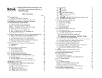
SPECIFICATIONS
S P E C I F I C AT I O N S
Number of input channels
Frequency band
Dynamic
Throughput rate
Digital trigger/tach
Generators
Connectors
Dimensions
Weight
Power
Battery
OR24
2 or 4
20 kHz
90 dB
4 x 20 kHz
Up to 20 V, up to 300 kHz
2 outputs, 3 Vrms - 600 1
BNC
250 x 170 x 45 mm
9.8 x 6.7 x 1.8 in
2 kg - 4.4 lbs
100-240 VAC
External, 90 min (option)
OR25 - Model 100
2 or 4
20 kHz
90 dB
4 x 20 kHz
Up to 20 V, up to 300 kHz
2 outputs, 3 Vrms - 600 1
BNC
415 x 270 x 55 mm
16.3 x 10.6 x 2.2 in
3.5 kg - 8 lbs
100-240 VAC , 10-30 VDC
Internal, 90 min
O R25 - M o d e l 30 0
2, 4, 8 or 16 all upgradable
20 kHz
90 dB
8 x 20 kHz
Up to 20 V, up to 300 kHz
2 outputs, 3 Vrms - 600 1
BNC pad + cable
415 x 270 x 90 mm
16.3 x 10.6 x 3.5 in
5 kg - 11 lbs
100-240 VAC , 10-30 VDC
Internal, 60 min
OR24
OR25
OR24 and OR25 PC-Pack II are delivered with traceable calibration report, software on CD, key disk for software options, installation and user manual,
carrying case and 12 months warranty.
In addition, OR25 PC-Pack is delivered with cigarette lighter adapter.
COM M O N SPECIFIC AT IONS FOR ALL MODELS:
FFT
Real-time band
Frequency range
Frequency resolution
Zoom
Trigger
Valid-reject
Display trace
1 mV to 31,6 Vrms, autorange, accelerometer and microphone constant current supply (ICP™), AC/DC/Float
100 V
90 dB
200 dB/octave
single-double integration / differentiation, time or frequency domain
A, B, C, programmable low-pass, high-pass, band-pass, stop-band
0 to 20 V, 300 kHz (over sampling)
2 outputs, 3 Vrms, 600 1
DC to 20 kHz
autosensing 100-240 VAC, OR25 only: 10-28 VDC, built-in battery charger
100-240 VAC and 10-30 VDC inputs, cigarette lighter cable, same dimensions as OR24
IEC 68-2-6 operating: 5-100 Hz, 5 mm, 2 g (5-500 Hz, 5 mm, 1 g)
IEC 68-2-7 10 g (11 ms, 1/2 sine), 70 g (3 ms, 1/2 sine)
IEC 68-2-7 20 g (11 ms, 1/2 sine), 100 g (3 ms, 1/2 sine)
operating 0°C [32°F] to 45°C [113°F], storage -25°C [-13°F] to 70°C [158°F]
complies with EMC Directive and Low Voltage Directive
Display type
Average
Overlap
Weighting
Generator 1
Generator 2
Export
4 ch. x 20 kHz, 8 ch. x 10 kHz, 16 ch. x 5 kHz continuous, 20 kHz in multiblocks mode
0.5 Hz to 20 kHz, 1, 2, 4, 5, 8, 10, 20, 25 progression
100 to 3200 lines
1 to 128
free run, level, external, manual RPM, delta RPM, delta time, delta level
normal, manual, automatic on overload
input signal, trigger, spectrum, cross spectrum, FRF H1 & H2 (magnitude-phase-real-imaginary), coherence, envelop,
spectrum of envelop, orbit, auto & cross correlation, DC level
2D, single or multitrace, overlay of live and saved traces, waterfall with section in time, frequency or order, XY
linear, exp, peak hold, ref. peak hold, in time or frequency domain
0%, 25%, 50%, 75%, 90%, max, retrigger
Hanning, Hamming, Flat-top, Uniform, Kaiser-Bessel, Exponential, (adjustable force and response), User defined
Sine, Multisine, Swept Sine, Random, Chirp, Burst, User (*.bin or *.txt file)
Sine with same Gen1-frequency and programmable phase and amplitude, non correlated Random Noise
Bin, Text, UFF (58), Matlab™
RECO R D ER
Continuous rate
Transient rate
Trigger
Length
Export
Display
8 ch. x 20 kHz, 16 ch. x 10 kHz on the disk of the PC
16 ch. x 20 kHz during 5 seconds
trigger signal, timer, manual
limited by the size of the disk, 2 bytes/ sample, 100 kB per channel per second (0 - 20 kHz band)
WAV, multichannel, 51.2 kHz sampling frequency, SDF
input signal, frequency spectrum, signal file
OFF -LI N E FFT
Play back
Output filters
FFT analysis
1 or 2 channels of the signal file to generator outputs, complete file, section, single or repeat
A, B, C weighting, programmable low-pass, high-pass, band-pass, band-reject
on complete file or section between 2 cursors, same parameters and display as real-time FFT.
continuous or block-by-block analysis on 1 or several channels
For options and NVSolutions®, please ask for the relative data sheets or visit our web site.
OROS, Inc. OROS S.A.
502 Shaw Road B-101 23, chemin des Prés
Dulles, VA 20166-9435 ZIRST 4403
USA F-38944 Meylan cedex
Phone: +1.888.200.OROS Phone: +33 476 90 62 36
Fax: +1.703.478.3205 Fax: +33 476 90 51 37
E-Mail: [email protected] E-Mail: [email protected]
Matlab is a trademark of Mathworks Co.
Windows 98, 2000, NT4, ME and XP, Word and Excel are
trademarks of Microsoft Corp.
ICP is a trademark of PCB Piezotronics Inc.
NV Solutions is a trademark of OROS SA
OROS SA is
ISO 9001
certified
www.oros-signal.com
C002-092-1
PC-PACK ANALYZERS
Specifications not biding - design: Genco Oil - F38800 / photos: Nocomment! - Genco Oil
Input voltage range
Overload Protection
Dynamic range
Antialiasing filters
Input conditioning
Input filters
External trigger-RPM
Generator
Frequency band
Power supply
OR24 battery option
Vibrations
Shocks operating
Shocks storage
Temperature
CE marked
www.oros-signal.com
m er …
am
ra
c
ce
th
The compact multichannel analyzers for sound & vibration measurements
e c t in p u t f o
O R 2 4 & O R 2 5 P C- PA C K I I
d ir
OR24 & OR25 PC-Pack II
Big on performance, small in size
ler
ome
te r s, i m
The OR24 and OR25 PC-Pack II combine the power and
flexibility of a laptop PC with the precision of a dedicated
instrument. They feature all functions of a sophisticated
dynamic signal analyzer in a rugged package to be connected
to a laptop PC for true, go-anywhere portability.
The PC-Pack II is available in 3 models:
- OR24: 2 or 4 channels - 2 kg (4.4 lbs)
- OR25 PCP102 and PCP104: 2 and 4 channels - 3.5 kg (8 lbs)
- OR25 PCP 302, PCP304, PCP308 and PCP316: 2, 4, 8 and 16
channels - 5 kg (11 lbs)
OR24 and OR25 PC-Pack II are designed for mobile
applications and on-the-move engineers.
The aluminum housing and corner rubber pads protect it
from shocks.
They comply with standard shock and vibration tests for
industrial use.
The internal temperature is controlled by a quiet fan, which
can even be switched off during sensitive acoustic
measurements.
All calculations are performed in real-time in the analyzer,
ensuring real-time rates as high as 20 kHz for both FFT ,
Octave or Order analysis. Measurements are thus
independent of the performance of the PC. The PC-Pack II
can be installed on any PC.
The signal recorder mode can continuously record the time
domain signals from 8 channels or more (depending on the
PC) up to 51.2 kHz (gap-free) sampling rate.
ic
Light and robust
The OR24 and OR25 PC-Pack II offer high measurement
quality: 0.05 dB gain matching, 0.1° phase matching,
guaranteed by self-calibration circuitry. The high 90 dB
dynamic range and extremely low noise level comply with
the most demanding measurements.
.. . m
These models use the same software range and the same
technology: up to 16 channels of real-time FFT, Octave and
Order analysis, a multichannel signal recorder, and all the
software facilities for post-analysis and report editing.
Communication between the PC and the analyzer is made
via an interface designed for industrial environments.
Speed and precision
ro
ph
one
s
High technology and ease of use
rem
ot
The purpose of PC-Pack II is to make your measurements
easier.
Integrated power supply, integrated as well as
external battery, cigarette lighter adapters, BNC
connectors, convenient carrying case, all
these features make it easy to carry and
operate anywhere.
The software runs under any version of
Windows™: W98, W2000, WNT4, WME or
WXP. As standard, analyzers are delivered
with a PC Card for notebooks. For use
with a desktop PC, a PCI interface is
available in option.
The analyzers support the most
common data formats for easy
communication with other systems.
e
co
ntr
ol
t he
l a pt o p
The OROS NVSolutions® range offers
complementary packages for specific
analyses.
st ra p p
ed
w
it h
PC
ca
r
d
in
ter
face
pa
c
Standard software package
Standard software package
FFT ANALYSIS FEATURES
OR24 and OR25 PC-Pack II come with a complete set of software
modules for FFT analysis, compiled in 2 main programs:
- OR763: Real-time FFT and order analysis
- OR773: Recorder and off-line FFT and order analysis
• Pr oject man agemen t:
it organizes data into a project-subproject-measurement structure:
configuration, settings, calibration data, transducer database, time
domain data, frequency domain data, ...
Real- time FFT - OR763
Off -Line FFT - OR773
• Guided men u s:
These two programs run in the same environment, totally integrating
all the peripheral features: project and configuration management,
transducer management, measurement saving, importing and exporting,
report editing.
•
the Next/Previous key is an easy way to explore all the set-up
menus in a recommended order.
With some practice, you will invoke directly any menu.
Displa y capabilities:
up to 32 trace windows, for time domain signal, spectrum, cross
spectrum, FRF, envelope, zoom spectrum, coherence or auto and
cross correlation...
The overlay capability lets display several traces in the same
window: then you can compare signals from different transducers
or different saved files.
• Displa y tools:
2D, 3D-waterfall, 3D-color spectrogram, orbit, labelling, lin. and
log. scale in both axes, dB, ESD, PSD, simple/double
integration/differentiation, graphic zoom, autoscale, cursor, full
or selected frequency band RMS indicator, units, 20 kHz band
overload indicators...
• Cur sor s an d marker s:
manual, harmonic, peak, side band, band power, octave bands.
OR763 performs the FFT in real-time on the data from the analog
input channels. OR24 and OR25 offer a computation power
capable of processing the flow of data continuously. It supports
real-time FFT on 4 channels at 20 kHz , with overlap, averaging,
frequency resolution up to 3200 lines and various pre-processing
functions like filtering or A-weighting.
The continuous FFT rate is 10 kHz on 8 channels and 5 kHz on 16
channels. This rate can be extended to 20 kHz on 16 channels
using multi-block analysis, and the internal memory.
The real-time FFT mode displays the selected traces live: time
domain like an oscilloscope, and frequency domain functions, in
2D or 3D plots. Some additional information is displayed: RMS
value and overload indicators.
The WAV signal file stored with the recorder is loaded in the offline mode for processing and analysis. You can then analyze the
file or a section of it with the same capabilities as in the real-time
mode. It is possible to zoom the signal file, and to move block by
block in the file or continuously.
In addition, the off-line mode offers a playback function: 1 or 2
channels of the recorded signal can be selected and played on
the generator outputs, directly or filtered: low pass, high pass,
band pass and band reject with programmable cut-off frequency.
• Input fr on t -en d:
settings of the hardware analog channels (input voltage range,
AC/DC/FLOAT coupling, ICP™ source).
• Input pr e-pr ocess:
Recor der - OR773
Advanced Or der Analysis - OR763, OR773
some signal processing can be applied on the signal in the time
or frequency domain, like digital filters (low pass, high pass, band
pass, band reject), A, B, C or custom weighting, time or frequency
domain integration, RMS or peak detectors.
• Transdu cer man agemen t:
transducer database, units database, transducer calibration (with
calibrator or comparison).
• Triggers:
selected from any of the analog inputs or on the external
trigger/RPM input. In addition to this, delta RPM, delta Time, delta
Level, or Manual triggering are provided.
• Level mon itorin g:
this capability computes in real-time the RMS, Min, Max, filtered
DC and traces them against RPM or Time.
• Generators:
2 generators are available to generate various waveforms: sine,
swept sine, random noise, burst chirp, multisine, and also any user
defined waveform (with phase control and non correlated signals).
• R PM:
1 or 2 tach. signals can be connected to any of the analog inputs
or to the external trigger/RPM input. Some pre-processing features
are provided for cleaning the tach signal if necessary.
• Ex p or t:
AE2 (OROS binary), TXT, bitmap and metafile to Word™, UFF to
any analysis software package, MAT to Matlab™, SDF.
• R ep or t:
several modes of print out are offered. You can choose to print
directly what you have on your display, define a template and
print your data in this template.
This mode makes your PC a multichannel signal recorder, like a
DAT. You can acquire and continuously store 1 to 8 channels
within 20 kHz bandwidth (51.2 kHz sampling) , and 16 channels
within 10 kHz without any gap in the signal. The only limit in size
is the capacity of your disk. For instance, a capacity of 1 GB can
store 8 channels within 20 kHz band during more than 20 minutes
continuously.
During recording, time domain as well as frequency domain
signals can be displayed for monitoring.
You can do several records individually triggered by a time period
or a trigger signal.
The generators can be active during the recording if you want to
excite a structure and record the responses.
The data is recorded in a WAV format which support more than
2 channels, and the sampling frequency of 51.2 kHz. This WAV file
can be processed in most multimedia packages or playback with
a multimedia board supporting this sampling frequency.
A WAV signal file can be post analyzed in FFT mode as well as in
1/n octave mode or order tracking mode (as long as a tach signal
has been recorded).
For vibration analysis on rotating machinery during a run-up or
coast-down, it is interesting to display the vibration related to the
RPM speed, the order plot. The order n is the vibration related to
the nth harmonic of the rotating speed, and gives a representation
of vibration coming from phenomena occurring n times in a rev
of the machine.
The Real-time FFT software and the Off-line FFT offer this feature:
the signal is acquired according to the measured RPM speed and
the delta RPM selected for the triggering. A waterfall plot is then
displayed, and the order trace can be extracted from this waterfall.
Note: the meaning of Real- time FFT
The Fast Fourier Transform gives a direct representation of the signal in the frequency domain. This technique computes frequency
spectrum and derived results like FRF from time domain data acquired by blocks. Real-time can have two meanings: one, quite obvious,
is that you can see the frequency spectrum in live mode, continuously. This is equivalent to an oscilloscope in the frequency domain.
The second meaning, which is the real meaning, is that the computation takes into account all the time domain data to compute the
frequency spectrum. A consequence is that the computation rate has to be faster than the acquisition rate. This is a challenge for FFT
analyzers, but a necessary condition to have an exact representation of the signal spectrum. Any loss of time domain data results in
an error in the frequency spectrum. The real-time band is then a critical parameter if you want precise measurements.
OPTIONS
OPTIONS
Ad vanc e d Di agnosti cs
O r d e r Anal ysi s - OR79 3 6
This option gathers some tools dedicated to rotating machinery:
Cepstrum, Kurtosis, envelope listening, Bode plot and the Constant Band
Tracking (CBT).
CBT is a technique used to track orders. It is an option of the FFT mode,
and displays the energy in a selected frequency band around one selected
order, against RPM or Time. CBT operates like a bank of tracking filters. It
is possible to display up to 8 orders per channel, with an individually
selected frequency band.
Cepstrum and the other tools mentioned above are precious for vibration
diagnostics, to isolate phenomena in a rich signal, in order to identify the
source of the vibration (bearings, gears, misalignment, ...)
This mode runs in real-time and in off-line modes.
F FT b as e d 1 /3 Octave - OR 7932
Advanced Or der An alysis - OR7931
Time resampled order analysis is a key feature for in-depth investigation
of engines, transmissions, turbines or any rotating machine. This technique
directly computes and displays the vibration spectra in harmonics of the
shaft speed, called orders. The result is much easier to analyze than a
spectrum in frequency, since most of the vibration sources are related to
the rotation of the machine.
The OR7931 is based on a digital resampling technique, eliminating the
various problems associated to analog techniques and offers precision,
stability, and tracking capability for very rapid accelerating shafts. A runup from 1000 to 6000 RPM in a few seconds can be perfectly analyzed
with high precision. For slower run-ups, the analyzer can average the data
during the run-up to offer a higher precision.
The display capabilities are: spectra in order, traces of selected orders
against RPM or Time, waterfall display against RPM or Time, RPM profile.
It is possible to track up to 8 orders per channel + overall, and to display
them in one or several windows. A window edit function allows to overlay
order traces from various sources: orders, channels directly or
superimposed with saved data.
For transmission analysis, 2 tach. channels are typically supported.
This option can be used in real-time mode and in off-line mode.
NVSolutions
O R O S N V S o l u t i o n s®
OR24 and OR25 PC-Pack II offer very flexible and advanced
analysis tools for various purposes.
In addition to these analyzers, OROS proposes a range of
complementary solutions, developed by OROS or in
cooperation with OROS. A total compatibility and suitability
is then guaranteed.
OROS - Repor ter
This module is exceptionally easy and efficient for data browsing,
calculation, and report edition. Active documents make reports
easier and much more attractive.
Reporter
OROS - ODS
Complementary package to OROS-Reporter, it displays the
deflection shapes of a structure in operation. This is a precious
tool for development or troubleshooting. OROS-ODS includes a
geometry editor, and wizards for easy operation. Some additional
translators are included for data exchange with other analyzers
as well as software packages.
Color sp ectr ogram - OR7934
ODS
OROS - Modal
OROS - Modal is a complete package for modal analysis and modal
parameter determination. It supports SDOF as well as MDOF. It
includes OROS- ODS, a modal shape organizer and efficient
wizards.
This module computes and displays spectra of a signal in 1/1 octave or
1/3 octave. It is based on a technique using the FFT simultaneously in 3
frequency bands in real-time, and synthesizing the 1/3 octave spectrum
conforming to the IEC225 standard. The OR7932 is a complementary tool
to the FFT analyzer. It can simultaneously display narrow band FFT and
1/1 or 1/3 octave spectra including phase.
This option runs in real-time and in off-line modes.
Filte r s b ased 1 /n Octav e OR7933
This option supports the FFT mode and the Advanced Order Analysis
mode, and adds a time frequency color display capability.
This display is very efficient for following up the results at a glance.
The user can quickly locate the most critical points in the map, and then
zoom and edit. Functions are offered to get more details at these points.
The color spectrogram displays the main color map and 3 traces which
are 3 sections of the color map.
The real-time color map traces the history of the spectrum in frequency
or order domain, against the RPM or the time. The sections are related to
a selected RPM, a selected frequency, and a selected order. Moving the
cursor on the color map continuously updates traces, and enables you
to quickly find part of the map. An edit function allows you to set markers
on the display .
This mode runs in real-time and in off-line modes.
Modal
OROS - S ou n d I nte nsity
This package conforms with ISO9614, parts I and II. It performs noise
emission distribution analysis as well as sound power determination.
It controls directly the analyzer for easy acquisition, and supports several
types of probes with remote control.
The 3D color mapping is particularly efficient and readable.
Sound intensity
For many acoustics measurements, an analysis of the signal based on
filter bank technique is required. The OR7933 performs this using digital
filters conforming IEC1260 and IEC 225.
This module constitutes a complete 1/n octave analyzer: 1/1, 1/3, 1/12
and 1/24 octave.
- A, B, C, weighting
- LIN, EXP, LEQ, Fast, Slow, Impulse
- Signal generator
- Waterfall display
- RPM triggering
- Octave tracking
This option runs in real-time and in off-line modes.
OROS - Balan cing
Spectral weigh t filter s - OR7937
This option enables the selection of specific filters on any input signal, in
real-time or off-line mode.
These filters are often required for evaluation of comfort in vehicles. The
available set is : A, D, 1/A, A*D, 1/A*D, A*D[200-5000Hz], ISO2631 (Wc, Wd
and Wk), BSI6841 (Wb, Wc, Wd, We, Wf ), BSI6842 (Wh).
The spectral weight filters can be used in the FFT and 1/n Octave modes.
Supporting 1 or 2 planes, OROS- Balancing uses a special technique
usable even without stable speed.
The graphic interface guides the user for placing the trial and the
correction masses. Placing mass as well as removing material is possible.
A mass can be split when some position cannot support the correction
mass (blades).
Balancing