1
Combined Manual for Chief Starter Set,
DCS100 Command Station/Booster &
DT100 Throttle
Table of Contents
Page #
1.0 INTRODUCTION
4
1.1 LocoNet: The Digitrax Difference!
5
2.0 DCS100 COMMAND STATION/BOOSTER FEATURES
6
3.0 DT100 ADVANCED DIGITAL THROTTLE FEATURES
7
4.0 QUICK INSTALLATION GUIDE
9
4.1 Making Track & Booster Connections
9
Diagram 1: Chief Set Quick Start Hook Up
11
Diagram 2: Expanded LocoNet Connection Example
12
4.2 Plugging In Your DT100 Throttle
13
4.3 Run An Analog Loco on Address "00"
14
4.4 How To Select & Run A DCC Equipped Loco
16
4.5 Shutting Down the System
17
5.0 ADDING CHIEF COMPONENTS TO YOUR EXISTING BIG BOY SET
18
5.1 Adding a DCS100 To Your Existing Big Boy Layout
19
5.2 Using A DT200 Throttle With Your Chief Set
20
5.3 Add A DT100 Throttle To An Existing Big Boy
20
5.4 Differences Between "Chief" and "Big Boy" Operations
20
5.5 Converting Your DT200 to a DT100
21
6.0 POWER SUPPLY CONSIDERATIONS FOR BOOSTERS
22
6.1 Transformers
22
6.2 Batteries
25
7.0 TRACK WIRING CONSIDERATIONS
25
7.1 Sectioning the Layout
26
7.2 Reverse Section Wiring
26
7.3 Bi color Track Indicators
28
8.0 LOCONET WIRING COMPONENTS
29
9.0
DCS100 COMMAND STATION/BOOSTER
30
9.1 DCS100 Connections & Configuration Controls
30
9.2 DCS100 Indicators
31
9.3 DCS100 Audible Sounds & Their Meanings
32
9.4 DCS100 CMOS Battery Warning & Replacement
33
DT100 THROTTLE DIAGRAM
35
10.0 DT100 LOCONET THROTTLE CONTROL PANEL
36
10.1 General Color Codes
36
10.2 The Left & Right Throttle Knobs
36
10.3
10.4
10.5
Direction Indicators
Program Mode Indicator
Address Mode Indicator
36
36
37
10.6 LCD Display
10.7
Run/Stop
10.8
Select/Set
Mode/Dispatch/Display
10.9
10.10
Function/F0/Light Control
10.11 Function 1-8 Keys
10.12
&
Left & Right Throttle Direction Change Arrows
10.13 Up/Add & Down/Delete Arrows
11.0 DT100: MAJOR SYSTEM M ODES
11.1 Track Power On Mode
11.2 Track Power Off Mode
11.3 Stop Mode
11.4 Programming Mode
11.5 DT100 Unit Reset
12.0 LOCO MODE: RUNNING TRAINS
12.1 The Select Message
12.2 Two Digit Short Address & % Speed Display
12.3 Locomotive Speed Control
12.4 Locomotive Direction Control
12.5 Selecting the Locomotives You Want To Run
12.5.1 Selecting A 2 Digit Short Address
12.5.2 Selecting An Aliased 4 Digit Address From the Alias Roster
12.5.3 Editing Aliased 4 Digit Address Roster Entries
12.5.4 Selecting A 4 Digit Long Address Loco
13.0 WALKAROUND OPERATION ON LOCONET
13.1 Forcing A Selection, or "Stealing" A "Lost" Locomotive
13.2 DT100 Slot Following-"Training Mode"
13.3 DCS100 Loco Purging Strategy or Time Out!
14.0
CONTROLLING LIGHTS & FUNCTIONS
14.1 Controlling Functions On Consisted Locos
15.0 DISPATCHING LOCOMOTIVES
16.0 DECODER STATUS
16.1 Status Editing a Decoder
16.2 Note for Lenz, Marklin & Arnold Decoder Users
17.0
SWITCH MODE
18.0 ROUTES
18.1 DT100 Route Editing
Diagram 5: DT100 Display Mode Flow Chart
With Route, Signal & Clock Edit Modes
18.2 Triggering A Route From Your DT100 Keypad
19.0 MULTIPLE UNIT OPERATIONS:
19.1 MU-Link: Adding a Locomotive To A Consist
2
37
37
38
38
38
39
39
39
39
39
39
40
40
40
41
41
41
42
43
43
44
46
47
50
51
52
55
55
56
57
57
58
60
61
61
62
64
67
67
69
70
72
19.2 MU UNLINK: Breaking A Loco Out Of A Consist
19.2.1 Nested Consist Unlinking
19.2.2 Advanced Consisting
19.3 MU of Mismatched Locomotives
20.0 DT100 CONFIGURATION OPTIONS
21.0 DCS100 PROGRAMMING MODES DECODER PROGRAMMING:
CUSTOMIZING YOUR DECODER'S PERFORMANCE CHARACTERISTICS
21.1 Programming Track
21.2 Using Your DT100 To Program Decoders
21.3 Programming 2 Digit Short Address Decoders
21.4 Four Digit Long Address Programming
21.5 Programming Other Configuration Variables (CV's)
21.6 User Loadable Speed Tables
21.7 Operations Mode Programming
21.8 Programming DS54's
21.9 Digitrax PR-1 Decoder Programmer & Your PC!
22.0 DT100 FAST CLOCK
23.0 SHUTTING DOWN THE SYSTEM-DCS100 SLEEP M ODE
24.0 DCS100 OPTION SWITCH SETUP
25.0 MOTOROLA TRINARY FORMAT DECODERS
26.0 Troubleshooting
26.1 Clean Track
26.2 Reprogram the Decoder
26.3 Emergency Stop
26.4 Mechanical Drive Train Problems
26.5 Strange Lights (Not The Ones In The Sky)
26.6 LocoNet Doesn't Respond.
27.0 FCC INFORMATION
28.0 WARRANTY & R EPAIR INFORMATION
Index
73
73
73
74
75
77
78
79
80
81
82
84
88
89
89
90
93
94
98
100
100
100
100
100
100
101
101
102
105
1.0 Introduction
Congratulations on your purchase of a Digitrax Chief Starter Set, DCS100
Command Station/Booster and/or DT100 Throttle!
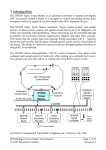
The overall design of the Digitrax Command Control system allows you to
create a working layout by connecting various system components in the
configuration that best meets your needs. The Digitrax system drastically
reduces & simplifies layout wiring; you probably won't need to rewire your
existing system. To create a DCC system you will need a Command Station,
a Booster, a Throttle & several mobile decoders for your locomotives.
LocoNet is the communications network Digitrax products use to put it all
together.
•Each system has one Command Station that generates the DCC packets that
tell the decoders what to do & produces Rail Sync so that all the devices
you attach to LocoNet work together. With the Digitrax System you have
a choice of several command stations to allow you to tailor your system to
meet your needs. In an effort to keep the price down, we have chosen to
combine command station functionality with other system hardware
components. The Challenger Command Station is included in every
DB100 series booster. The DT200 Command Station/Throttle is used as
the command station in the Big Boy Starter Set. The DCS100 Command
Station/Booster is the command station for the Chief Starter Set.
•Boosters receive the DCC signal from the Command Station, amplify it &
put it on the track as the power that runs the layout. You can have
several boosters on a system, each driving its own track section. You can
have both regular or auto reversing boosters depending on your needs.
•Throttles are input devices that tell the Command Station what you want the
decoders to do. You can have many throttles on your system. The
number is determined by the capabilities of the Command Station you are
using.
•The Decoders in the locomotives or under the switches or other accessories
receive the signal from the track, decode it & tell the locomotive or
switch/accessory what to do.
•There are many different combinations of Digitrax products that you can use
to set up a system that is just right for your application. You can also
combine Digitrax products with DCC compatible decoders, boosters &
computer software made by other manufacturers.
Your success with & enjoyment of our products are very important to us.
After all, this is a hobby & it is FUN!!! Please read this manual carefully
before you install your DCS100 & DT100. We have included lots of hints &
operating ideas based on our experience with the Digitrax system. If you
3
4
have questions not covered by this manual please contact your dealer or call
us directly.
To the average user this means Sophistication without Complexity. You
have a system that is easy to hook up, run & expand in the future. You don't
need to worry about the high-tech details; Digitrax has already sweated them
out for you. Just enjoy operating your layout- it's that simple & powerful!
1.1 LocoNet: The Digitrax Difference!
2.0 DCS100 Command Station/Booster Features
LocoNet is a powerful communications network especially designed for model
railroad operation. It is engineered for rapid response even when many
throttles & other devices are connected to the network.
•The DCS100 is a combination DCC Command Station & Booster. The
DCS100 operates as the command station & main system booster on a
Digitrax LocoNet system. It can also be used in conjunction with your
computer if you choose to do so.
•The DCS100 accepts throttle input from any LocoNet throttle (DT100,
DT200, BT2, Computer throttle & new Digitrax & LocoNet Certified
throttles to come soon)
• Control over 9,000 locomotive addresses.
• Aliasing capability gives you four digit addressing for ALL DCC decoders.
• Roster capability lets you set up the locomotives you operate most often in
an easily accessible list.
• Built in read/write programmer & separate service mode programming
output allows you to program each individual decoder's acceleration,
deceleration, start-voltage, mid-point voltage, loadable speed table, etc.,
without shutting down the layout.
• Operations mode programming lets you program expanded packet format
(EPF) decoders “on the fly” while they are on the mainline.
•128 speed step operation! You can select 14, 28, or 128 speed step
operation for each individual decoder so you don't have to sacrifice
performance if you have some decoders that have 128 speed steps & some
that don't.
• Basic, Advanced or UniVersal Consisting lets you choose how you handle
consists.
• Function Control. Control directional lighting & additional function
outputs from the keypad.
• Control up to 999 switch addresses from the DT100 keypad.
for
• Absolute switch position control with the DT100 keypad. Press
closed and
for thrown.
• Route capability to simplify complex yard operations.
• Switch Feedback memory. The DCS100 automatically handles switch
feedback reporting if you have LocoNet Certified switch feedback
modules programmed & attached to the system.
• Compatible with the NMRA Baseline DCC standard & RP’s.
• Customizable System Options let you set up how you want your system to
run. You can have “beeps” on or off, you can set time outs, set up purge
options, enable Motorola trinary modes, enable automated decoder
To engineer LocoNet, we used all of the best features of the powerful Ethernet
CSMA/CD Local Area Network, the most universal worldwide hookup
standard for computer networks. We ensured that LocoNet's protocol was
Peer-to-Peer, which any LAN expert will confirm, gives the most powerful &
expandable software architecture.
LocoNet offers you a powerful yet SIMPLE "plug & play" connection scheme
for wiring a high performance Digital Command Control railroad layout.
LocoNet is cost-effective & easy to maintain, & gives excellent high speed
total system performance. In particular, the system is designed to be sure that
as 100 or more throttles & hundreds of sensors & other devices are added to
the system, there will be no operator perceptible delays as the LocoNet system
executes all the operators' requests. Only a Peer-to-Peer type technology on a
true two-way Multiple Access network can meet these performance &
expandability targets.
Your LocoNet network allows very simple, "free form" wiring & has passed
the stringent Radio Interference rules of FCC Part 15 Class B, as required for
home installations. This makes adding extra devices & features simple- no
complex Bus connection & terminator rules to worry about. We have
even run throttles & sensors on a LocoNet system over 2,000 feet long using
"vanilla" telephone wire!
LocoNet is expandable so that as new features are added you can simply
connect & "overlay" these capabilities to your existing working LocoNet
system with minimal disruption or changes to existing hardware & software.
Only a carefully crafted & smart Peer-to-Peer network can offer this unique &
open-ended expandability.
So, LocoNet is more than just hardware, it is a number of operating system,
hardware, wiring, communications architecture & software innovations that
are synthesized together to create the total LocoNet system concept.
5
6
consisting & much more. A large range of customizable options.
Defaults to values that will work for most layouts.
• Motorola format compatibility mode lets you run DCC & Motorola format
trinary decoders at the same time.
• DCS100 Booster Capabilities give you a 5 amp High Efficiency booster
along with your command station.
A powerful 5 Amp Digital Command Control Booster Rated at 96VA
Accepts either 50/60Hz AC or DC input from your existing power
supply. Minimum input voltage: 12.6V AC or DC, Maximum input
voltage: 22V AC or 28V DC. The power supply you use should be within
this range & should be overload protected for its rated output, up to a
maximum of 5 amps.
Auto resetting over temperature & short circuit protection. Unique smart
protection will not "weld" derailed locomotives to the track.
Multi Scale selectable voltage for N through G scale operations.
User adjustable voltage trim.
Track Status indicator shows voltage & signal type (DCC or "Zero
Stretch" Analog Signal for conventional operation.)
Stabilized Track Drive Output. .
LocoNet Expansion Network for easy reliable system hook up & future
system expansion.
High impedance balanced signal input receivers on the LocoNet Interface
allow reliable boosting of several different types of command control
signals in large wiring plans.
Auto shutdown if command control drive signal is lost so that the layout
will not convert to DC operation if a cable or connection is broken. The
trains won't just "take-off" if they are not getting the DCC signal.
•DT200 Compatibility Mode. All DT200’s in the system become
walkaround throttles & will be able to perform all the same functions as
before if you use a DCS100 as the system command station. The
DT200's will still be limited to 127 locomotive & switch addresses.
•Brake Section Generator, the DCS100 can be configured to generate DCC
Broadcast Stop or "Brake Section signals" when the Programmer is not
in use. Simply add a second DB100a booster & some simple relays,
ballasts & wiring to create automatic signal-controlled STOP sections.
•The DT100’s display is a large easy to read LCD with four digits & other
indicators. It also uses several LED’s to indicate status.
•The DT100 is different from most throttles you have ever used because it has
two sets of throttle controls on a single hand held. The left hand throttle
knob & the left hand direction arrow key work together to control the
speed & direction of one train while the right hand side can control
another train at the same time. This arrangement is particularly useful if
you are operating alone & want to have two trains under your control.
The dual throttle arrangement makes consisting & helper operations
simple & much more prototypical.
•The DT100's throttle knobs are encoders rather than potentiometers. When
you turn the throttle knob, it rotatesmore than one turn from 0 to full
speed. These knobs give you incredibly fine speed control & when you
select another loco, the throttle knob position does not change the speed
of the new loco selected. No more rushing to adjust the throttle to match
the loco's current speed! (Note: If you prefer push-button operation, just
use the up & down arrow keys.)
•Displays aliased 4 digit addresses for baseline, 2-digit DCC decoders
•Supports 4 digit addressing with 14 bit or long address expanded packet
format (EPF) decoders
• Function Control. Control directional lighting & up to 8 additional function
outputs from the keypad.
•Displays switch position & can also show actual switch feedback.
•Αccess to three service mode programming methods
•Αccess to operations mode programming (programming on the mainline).
• The DT100 operates as an advanced throttle on a DT200 (Big Boy)
Command Station, too!
•Fully networked user configurable Fast clock, with Editor.
•Individual Throttle 24 hr Fast clock Alarm setting
•Editor to create & modify Routes
•Advanced locomotive sharing capability to allow supervised operation &
future advanced system features
• Customizable for user throttle preferences. You choose whether the throttle
knobs have straight line ballistic tracking, set up default mode for new
decoder address set up & more.
3.0 DT100 Advanced Digital Throttle Features
•The DT100 is a full featured advanced DCC throttle. It works as an
advanced throttle on LocoNet when another device such as a DCS100,
DT200 or a computer is acting as the command station.
7
8
4.0 QUICK INSTALLATION GUIDE
These simple instructions will get your Chief starter set up & running
quickly. If you are adding a DCS100 or DT100 to your current Digitrax
system please refer to section 5.0. You can investigate the specifics later but,
for now let's get your trains running. A full description of all controls &
technical reference information are included later in this manual.
Before you begin your installation be aware that the addition of DCC to your
layout will not correct existing wiring problems. Usually, if you can run an
analog engine smoothly on your railroad, you won't have a problem hooking
up DCC. If you do have concerns about your existing wiring, start by running
the Chief on a separate loop of temporary track.
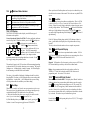
F) The DCS100 will "beep" & the "Power ON" indicator
will light up
GREEN. Also, the
indicator will glow steady RED, showing that the
unit is in "RUN" mode & that the LocoNet network is OK. If the unit has
indicator will be GREEN with a single brief
been configured the
"wink" off about every 4 seconds. The red “OVER TEMP” light will also
be lit. The full meanings of these indicators are covered in section 9.2.
G) The "Track Status" indicator should be off at this point. This is the
normal system default after input power is applied to the DCS100.
Now that the DCS100 is ready to go, we can connect a throttle to it & start
running the layout.
4.1 Making Track & Booster Connections
See the “Chief Set Quick Start Hook Up Diagram,” Diagram 1.
A) Start with the DCS100 & your conventional power pack or other suitable
transformer. See section 6.0 for information on how to choose an
appropriate power supply.
B) Set the
SCALE switch on the DCS100 to the scale you are running N,
HO, O\G(also used for S). To get the best low speed performance, we
recommend using the DCS100 in the "N" scale setting (even if you are
running HO). When running analog locomotives (without decoders) we
strongly suggest that you use the "N" scale setting to give quieter
operation & generate less heat build up in the analog engines.
C) Set the
MODE switch on the DCS100 to the "RUN" position.
D) The GREEN wire on the back of the DCS100 provides electrical safety
features and an RF ground reference for minimum radiated noise. It should
be the ONLY point of any installation that is connected to the AC safety
ground pin provided on most 3 pin 110V AC power sockets. If the power
outlet is a 2 pin ungrounded unit, this ground terminal can be connected with
a GREEN 14 AWG multi-stranded conductor to a cold metallic water pipe
ground, as defined in the National Electrical Code. This is a safety
precaution that should not be ignored.
E) Connect the two POWER IN terminals to the output of your transformer
or power supply source. Turn on your power supply to send power to the
DCS100.
9
10
Diagram 2: Expanded LocoNet Connection Example
Diagram 1: Chief Set Quick Start Hook Up
11
12
4.2 Plugging In Your DT100 Throttle
Initial DT100 Power Up & Throttle Option Set Up:
1. Install a 9V battery in your DT100 in the battery compartment. The
positive "+" and "-" terminals are marked inside the battery compartment.
(The DT100 is protected against incorrect battery polarity so, don't worry if
you install the battery "backwards.")
2. The DT100 will beep & show a 4 digit unique ID code # for about 1.5
seconds.
3. The DT100 will display the throttle set up option codes. Use these initial
defaults by following these instructions. The primary option code #
"oP:01" will be displayed. If you do nothing, in about 12 seconds the
DT100 throttle will automatically go to "idLE" and the default values will
be used when operating this throttle. Twelve seconds can seem like a long
time so, you can speed up things by pressing the
key. The DT100
display will change to the secondary option display "oS:03". Press the
key once again to accept the default settings for the secondary options. The
DT100 will display "idLE." Once your DT100 has "idLE" in the display
you can proceed to the next step.
See section 20.0 for available throttle options & how to set them up.
Logging Onto The LocoNet System:
1. Plug the DT100 into either LocoNet Jack on the DCS100.
2. The DT100 will beep & the LCD display will change from "idLE". If the
DCS100 Booster section is not supplying track power to the rails, both the
DT100's direction indicators will be steady ORANGE, the DCS100's
Track Status indicator will be off and DCS100’s Over Temp Indicator will
be on. If you already have more than one booster on your layout, the
DCS100 is commanding all other boosters to have their track power OFF,
too.
Turn On Track Power:
1. Press down & hold the
key then also press the
key. This
commands the system to turn on Track power.
2. The combination
&
will turn off all system track power.
Checking For Run State:
1. The DT100's direction indicators
will be flashing ORANGE if the
track is powered but is in "Stop" where all mobile decoders are powered
but commanded to stop. The DCS100’s Over Temp indicator will be lit.
2. To change from "Stop" to "Run," press down & hold the
key then also
press the
key. The direction indicators
will no longer be ORANGE
but will show the direction of the decoder assigned to the adjacent throttle
knob. GREEN for Forward, RED for Reverse & OFF for no address
selected. The DCS100’s Over Temp indicator will no longer be lit. Each
13
time you hold the
&
keys down the system will toggle between
"Run" & "Stop" with track power on.
Connect The Layout To The Chief:
1. The DCS100 track status indicator should now glow ORANGE, indicating
that the track is powered.
2. Connect the Rail A/B terminals to your track. (You can also connect the
Programming A/B terminals to a separate isolated Programming track that
is not connected to any of the rest of the layout at this time if you wish.)
Note: During your initial installation, we recommend that you make these
connections after powering up the DCS100 & DT100 so that you will be
able to determine that your DCC equipment is working properly prior to
introducing any potential outside wiring problems. Once you have
completed the initial installation, these 2 sets of wires usually remain
permanently connected from their respective tracks to the DCS100. If your
layout has any short circuits & you connect it to the DCS100's RAIL A/B
terminals, when you power up the DCS100 it will beep up to 5 times &
shut down the RAIL A/B terminals until the fault is cleared.
Once your track is powered without any faults, you can proceed to select &
run DCC and analog locomotives. We recommend that you run an analog
locomotive first.
4.3 Run An Analog Loco on Address "00"
Note: If you are running a German Version of the DCS100, you will not be
able to use the analog feature described below. In this case, continue with
section 4.4 after you have installed a DCC decoder in your locomotive.
How to Select Address "00":
Note: With the DT100 you can control two different addresses at the same
time, one on the Left Throttle and another on the Right Throttle. Because
only one throttle can be displayed on the DT100's LCD screen at a time,
we use the direction indicator to indicate which side is currently "display
active". The "display active" throttle is the one with the flashing RED or
GREEN direction indicator .
1. Turn the Right Throttle Knob "R" a 1/4 turn in either direction to activate
the Right Throttle. The display will show SE:L-, indicating that no
Locomotive is selected on the Right Throttle & prompting you that the
key must be pressed to activate a selection in this throttle.
14
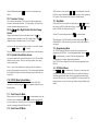
2. Press the
key to select an address.
The display will typically show 00:03,
with the 2 digits in the "Address" side
(left hand side) of the display flashing
to let you know that you need to select
an address. The "LOCO" flag on the screen will also flash during address
"browsing" or selection. Note: During 2 digit loco address selection, the
right hand side of the display shows complete status information of any
locomotive address in the display. Section 16.0 gives details of locomotive
status codes & what they mean and how you can use them in your
operations.
3. Turn either throttle knob, or use the
keys, to scan or "browse"
through the addresses until you reach the address number “00”. Notice,
turning the knob clockwise increases the loco address number & turning
the knob counterclockwise reduces the loco address number. When you
have scanned to the address you want, '00' in this example, press the
key again to SET this address active in the Right throttle. The display will
stop flashing & the direction indicator
next to the Right throttle will
flash GREEN indicating the Right throttle is the "active display" throttle &
the system assumes that the locomotive is going forward. Note: Since this
is an analog loco the actual direction is determined by the orientation of
the track feeds and how the loco is placed on the track. In the case of an
analog loco, the direction indicator
may or may not match the physical
direction of the loco. In the case of a DCC loco the direction indicator
will always match the actual loco direction. If you press the
(right
arrow) key to change direction, the direction indicator will flash RED
indicating that the loco has changed direction.
Checking Analog Mode:
Before placing an analog locomotive on the track you should
1. Turn the Right Throttle knob "R" clockwise slowly to 99% or full speed.
The DCS100 "TRACK STATUS" indicator should change from ORANGE
to more RED or GREEN indicating that we will be able to control the
analog locomotive on the layout.
2. Press the reverse
direction key for the right throttle. The right
direction indicator will change from blinking GREEN to blinking RED.
Also the TRACK STATUS indicator on the DCS100 will change from
RED to GREEN or vice-versa.
3. Once you observe these "track status" indications, turn the Right Throttle
counter clockwise down to 0% speed.
4. Place an analog locomotive on the track fed from the DCS100 Rail A/B
terminals. Remember, that we recommend that you use the "N scale"
15
setting when using an analog locomotive on your layout. The locomotive
should be still on the layout and you will hear the locomotive "sing"
slightly due to the DCC track signal. Once the analog loco is moving, this
sound will change and be less noticeable.
4. Use the Right Throttle knob to run the analog locomotive. As the value in
the % SPEED display increases, the locomotive on the track will begin to
move.
5. Once you have successfully run an analog locomotive, then you can add a
second locomotive that is equipped with a decoder. Follow the instructions
in your Decoder User's Manual to complete the decoder installation and
proceed to the next step.
4.4 How To Select & Run A DCC Equipped Loco
In order to select a DCC locomotive to run on either throttle, you must know
its address. All Digitrax decoders are factory programmed to the default 2
digit short address "03." If your decoder has not been re-programmed then
select "03" as the address for the Left Throttle knob "L." If you do not know
the address of the DCC locomotive you want to run, you have two options:
You can read back the actual address of the decoder using the programming
track as outlined in section 21.1, OR you can re program the decoder as
outlined in section 21.3 or 21.4.
Selecting A 2 Digit "Short" DCC Locomotive Address:
This Quick Installation only deals with DCC locomotives equipped with the
decoder that came with your Chief Set. These decoders are factory
programmed to use 2 digit short addresses and are capable of 128 speed step
operation. If you wish to use other decoders during the Quick Installation
procedure please see the notes below. Refer to section 12.5.2 for information
on using the Chief's aliased 4 digit addressing capabilities & 4 digit long
address (also called extended packet format, EPF or 14 bit addressing)
capabilities.
1. Turn the Left Throttle Knob about 1/4 turn to activate the left hand
throttle.
2. The display will change to SE:L- to let you know that the Left throttle is
display active but has no loco address selected.
3. Press the
(Select/Set) key. SE:L- will begin to flash.
4. Use either the throttle knob or the
keys to scan for the locomotive
address you want to run. Address "03" in this example. When the address
you want to run is in the left side of the display, press
(Select/Set) to
SET this address as the active address in the Left Throttle.
16
5. The left throttle direction indicator will flash GREEN indicating that
the Left throttle information is currently displayed & that the DCC loco's
direction is forward.
6. Now use the Left Throttle Knob to run the DCC loco you have selected
and set to the Left throttle.
7. Since the display can only show information for one throttle at a time, the
throttle direction indicator shows which throttle is on display by
flashing. Notice when we started working with the Left throttle that the
Right direction indicator stopped flashing & became a steady color
indicating the direction of the Right throttle's locomotive. To display the
Right throttle address & % speed all you have to do is move the throttle
knob or change the loco's direction.
By now you are running two locomotives (one analog and one DCC) and you
have learned some of the key concepts of using the DT100!! Please read the
following sections for more in depth information about other features &
capabilities of the Chief set. ENJOY!
QUICK INSTALLATION Notes for Users of Non-default Digitrax Decoders
and Decoders Made by Other DCC Manufacturers:
1. The DCS100 command station defaults to 128 speed step operation so, if
you are using a DCC locomotive with a decoder that does not have 128
step capability, please refer to section 16.0-16.2 for instructions to modify
or Status Edit the speed step mode that the system will use for this
locomotive address. OR see section 24.0 to change the global System
default from 128 Steps to something else.
2. If you can't control the operation of the lights in your locomotive with the
DT100 (in default 128, or 28 speed step mode), be sure that the decoder
itself is programmed in advanced 28 speed step mode. Please refer to
section 26.5 "Strange Lights" for corrective measures.
4.5 Shutting Down the System
When you are finished with the quick installation session, you can shut down
the Chief & LocoNet by simply switching the DCS100 "Mode" switch to the
"Sleep" position
. At this point all attached DT100 &/or DT200 throttles
will go to "idLE" indicating that they are powered down and in the "sleep"
state. We recommend leaving the power to the DCS100 on all the time. It
consumes less energy than a 20th of a normal household lamp and in this
state the DCS100 provides keep alive power to all throttles that are connected
properly to LocoNet. This conserves throttle battery life.
That's all there is to it!
17
When you are ready to resume your session exactly where you left off, simply
switch the DCS100 "Mode" switch back to the "Run" position
. The
attached DT100's and DT200's will beep within a couple of seconds to
indicate that LocoNet is active again and the "idLE" displays on the throttles
will change.
If the track status indicator did not come on when you switched the DCS100
back to "RUN" mode, then press the
&
on any DT100 to restore track
power.
At this point you have placed your Chief set in service & can now continue to
add to the layout, LocoNet system & operations as you desire. See diagram 2
to get an idea of how to add a host of other Digitrax & other vendors' LocoNet
Certified components & expand on the Chief set as the core of a very
powerful & expandable networked system!
If you had problems at any step in this Quick Installation section, we suggest
you try backing up a step until you get correct results. We carefully set up the
installation procedure so that if you follow them carefully, any problems you
encounter will be easy to isolate & debug.
If you have any questions or problems, we encourage you to call, fax or e-mail
us or your favorite Digitrax dealer. We have a lot of experience at helping a
diverse range of customers with successful installations. We have staff
available to help during normal business hours, so if you are "spinning your
wheels" we would be very glad to help.
5.0 Adding Chief Components To Your Existing Big
Boy Set
With your Big Boy Set, the DT200 acts as both Command Station & Throttle
for your system. The DB100 series booster is a stand alone booster. With the
Chief Set the DCS100 acts as the Command Station & Booster & the DT100
is your Throttle.
You can add either or both the DCS100 &/or the DT100 to a system that is
already running with a DT200 command station (Big Boy Starter Set).
Adding a DCS100 to your existing Big Boy will give you
1. The ability to run more engines at a time.
2. Complete walk around capability for all DT200 throttles.
3. Nested Consisting (using consists as part of other consists).
18
4. The ability to run Motorola Trinary Format Decoders on your LocoNet
system.
5. No LA-1 or LA-2 needed.
6. Throttle keep alive is built in so there is no drain on the battery.
7. Customizable system features.
8. DT200's will show actual switch position.
Adding one or more DT100's to your Big Boy will give you
1. Less expensive full featured throttles.
2. Fast Clock Display in all DT100's on your system.
3. DT100's will show actual switch position.
4. Customizable throttle options like ballistic tracking.
If you are an experienced Digitrax, Big Boy or LocoNet user & are adding a
DCS100 to a working Big Boy LocoNet system, enter at any installation step
you feel comfortable with. Refer to the system diagrams 1 &2 in this manual
and to the hook up diagram in your Big Boy manual for typical connections.
Be sure to review the display differences between the DT100 & the DT200 if
you are using a DT100 for the first time.
5.1 Adding a DCS100 To Your Existing Big Boy Layout
Please note: You will NOT use the DT200 as a command station when you
add the DCS100. You will NOT use an LA1 or LA2 when you use the
DCS100.
1. Unplug your DT200 master (command station unit) from the system &
remove its battery to clear it from master mode.
2. Disconnect the LA-1 or LA-2 from your DB100 booster & existing
LocoNet wiring. Put it away, you won't need it as long as you are running
with the DCS100 as your command station.
3. Connect the LocoNet cable that was connected to the "B" end of your LA1
or LA2 to the LocoNet "B" port of the DCS100. Use a male to male 6
conductor jumper from the LocoNet Port on the DB100 booster where the
LA-1 or LA-2 was plugged into back to the DCS100 LocoNet port "A."
Note that the DCS100 and DB100 LocoNet A & B ports are
interchangeable.
4. Reinsert the battery in your DT200 after a minute or so & the DT200 will
display "idLE." DO NOT make the DT200 a command station, the
DCS100 is handling that part of your system now. Plug in your DT200
anywhere on LocoNet & run trains as you did with your Big Boy. The
DT100, DT200's & any other devices can be connected anywhere along the
LocoNet wiring.
5. The expanded Chief set diagram 2 shows one way you might choose to set
up your wiring for this conversion. The main point to note is that you do
19
not have the LA1/LA2 wiring adapter anymore, & you can hookup all
LocoNet ports in the most convenient & sensible manner.
5.2 Using A DT200 Throttle With Your Chief Set
To use your DT200's with your Chief Set, insert the battery in your DT200 &
the throttle will display "idLE." DO NOT make the DT200 a master
(command station), the DCS100 is handling that part of your system now.
DO NOT plug in an LA-1 or LA-2. Plug in your DT200 anywhere on
LocoNet & run trains as you did with your Big Boy.
A DT200 that is running as a throttle on a DCS100 command station will
work just like it always has on a Big Boy. As an added bonus, there are
several additional features a DT200 can access when it is running with a
DCS100 as the system command station. For example, the DT200 can now
work with "nested" consists, set up "advanced" consists, display the actual
position of all turnouts and can select & run locos with Motorola Trinary
Format decoders on the layout.
5.3 Add A DT100 Throttle To An Existing Big Boy
Simply insert the battery in your DT100, setup any Throttle options you wish
to change & plug it in to any LocoNet Jack. It is ready to run. See section
22.0 for information about the specifics of running and Editing the Fast Clock
feature.
5.4 Differences Between "Chief" and "Big Boy"
Operations
Differences between the DT100 & DT200: The following are differences
that users of DT200's will notice when they use DT100's.
A) Steady ORANGE in DIR indicators show that Track power is OFF.
B) Flashing ORANGE in DIR indicators show that the track is
“idLE”/Paused/Stopped (In the DT200 this was indicated by a flashing
colon in the LCD).
C) Flashing Colon (with no other mode flags) means that the fast clock
time is being displayed on the LCD. All DT100's have a synchronized
networked fast clock with an integral 24 hr Alarm. The fast clock will
synchronize between DT100's even when they are operated on a Big Boy
system with a DT200 as the command station.
D) The Switch commands are explicit "Thrown" & "Closed" commands
rather than simply toggle commands as in DT200.
E) The DT100 can control F5-F8 when the
key is pressed and held
down while pressing the bottom row key corresponding to the function you
want to control.
F) The DT100 can access the DCS100's separate service mode programming
output. This means that you can program decoders without shutting down
20
operations on the main track. See section 21.1 for full details on this
programming track. Programming to loco's on the mainline [operation
Mode programming] is also available. See section 21.7.
G) The Expanded Address Mode Indicator
will blink RED when the
address being displayed is an aliased four digit address & will be steady
RED when the address is a four digit long address. The
indicator will
be off when using two digit short addresses.
H) The DT100 can automatically recover common purged loco's when logged
back on to LocoNet.
I) The DT100 has a feature called "slot following" to allow for future products
that will allow speed supervision by a computer or other device (for
example, signal approach speed limiting). Today you can use this feature
for training new operators or supervising inexperienced operators. You
can do this by concurrently logging on to (or "stealing") the loco that is
currently "in-use" by another throttle. If a DT100 detects changes to its
locomotive it will track the changes, & if the loco is active in the display,
the speed/direction will update in the display & the unit clicks. See section
13.2 for a full discussion of this feature.
J) The DT100 has provisions for programming components of the future
Digitrax Signaling System. Compatible with data format supported by
Tannersoft/Winlok, etc.
K) The DT100 has a throttle option mode that is accessible when you first
power up each throttle. This mode allows you to configure your throttle for
Ballistic or Straight Line tracking, Audible Feedback On or Off, Fast Clock
On/Off & much more. See section 20.0 for DT100 Option setups & values.
L) The DT100 has selectable Ballistic knob tracking & auto-repeat +/- keys.
If a DT200 has been used on a Chief set & is going to be used as the Master
Command Station for a Big Boy set, this throttle must be 'reset' to erase the
Chief setup information it may still carry. To do this, simply remove the
battery to power down the throttle and then replace the battery to reset the
throttle. OR do a throttle reset by pressing
&
simultaneously.
,
If the DT200 is just being used as a throttle on a Big Boy, this step is not
needed.
5.5 Converting Your DT200 to a DT100
Your DT200 can be converted into a DT100 with capability of accessing all
the expanded Chief features. Once this conversion is made please remember
that your DT100 is only a throttle & does not have command station
capabilities. Therefore, a DT100 cannot act as a command station in a Big
Boy Set. So, changing your DT200's into DT100's is really a conversion &
not an "upgrade" because some features are lost while others are gained. This
conversion can be done by the factory or by most local dealers. Please contact
21
either Digitrax or your dealer before sending in your throttle for conversion so
that we can schedule a good time for the work to be done so that you are not
inconvenienced by a long wait.
6.0 Power Supply Considerations For Boosters
The DCS100 accepts a minimum input voltage of either 12.6V AC (50/60
Hz) or DC. Maximum input voltage is 22V AC or 28 V DC. You can use
either AC or DC from a model railroad power pack or you can use a generic
transformer. The power pack must be overload protected for its rated output
up to a maximum of 5 amps.
The DCS100 contains a high efficiency DCC booster section that stabilizes
the track drive voltage to be related to the scale setting selected. It trims any
excess input voltage as heat into its large capacity heatsink. For maximum
current drive capacity select the lowest input voltage possible for the
particular scale. For N scale you can use 12.6VAC transformers of sufficient
current capacity. The optimal input voltage for use with the HO setting is a
12.6V AC to 16V AC transformer, & the O/G setting works well with an
18VAC transformer.
You can use other values, but the values recommended above will give
maximum sustained drive power. If you have DC power use the same voltage
as the AC values given here.
The DCS100 booster section has a max. output current limit of 5 amps. This
means that when the booster sees a 5 amp or greater load, it regards this as a
short circuit and will shut down until the load is removed or reduced below
the 5-amp threshold.
Actual continuous output current depends on several factors.
1) Input supply voltage
2) Room temperature / airflow over booster heat sink
Higher input voltages increase the amount of heat that must be dissipated by
the booster heat sink. If the heat sink does not get sufficient airflow or the
heat sink is blocked, the booster will eventually reach an OVERTEMP state
and shut down.
A small fan blowing cooling air on the DCS100's heatsink will also help to
maximize the sustained current capacity.
6.1 Transformers
There are many transformers & power packs that can supply the input power
for the DCS100 &/or DB100. Most regular DC train control packs do not
22
have enough power to supply the full power potential of the DCS100 &/or
DB100 booster, since they were typically designed to only run 1 locomotive in
a blocked system. You could temporarily use these lower capacity power
packs to test the system & demonstrate operations with a limited locomotive
count. To get the full power potential you will probably need to hook up a
suitable transformer with a higher power rating.
You should be very careful in hooking up a transformer to be sure that you do
not create a shock or fire hazard. Many modelers have safely hooked up line
transformers when creating their own conventional DC throttles, from one of
the many "do it yourself" project articles.
If you are not trained to safely work with 110 Volt input
wiring, we strongly suggest you consult with an electrician.
In particular you must be certain to fully isolate the Primary power supply
input to the transformer from the Secondary or low voltage side. A Primary
fuse is needed to ensure that if a fault develops that the user is forced to check
the unit carefully before returning it to service.
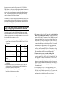
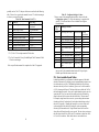
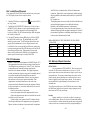
The following is an example list of components for building your own low
cost power supply for use with the DCS100 &/or DB100 using 110V/60Hz
AC line power
Description
Part #
Est Cost Supplier
16V AC 6.25 Amp Transformer 4-06-8016 $19.95
MCI
Trans
Line Cord
Q114-ND $ 1.31
DigiKey
1 Amp 3AG Slo-Blo Fuse
F319-ND
$ 4.01
DigiKey
per 5
3AG In Line Fuse Holder 150145 F049-ND
$ 2.32
DigiKey
5 Amp Fuse holder-type Circuit PB186-ND $ 2.89
DigiKey
Breaker
Heat Shrink Sleeving
DigiKey
The Phone Number for MCI Transformers is 1-800-MCI-TRAN (In NY dial
(516)587-0510)
The Phone Number for DigiKey is 1-800-DIGIKEY (DigiKey is also an
excellent source for 6 conductor phone wiring supplies needed for the
LocoNet network connections described later.)
Consult your local dealer to help you find an appropriate power supply.
Many dealers offer their own power supplies.
23
1) Most important is to be sure the 110V input voltage is safely isolated from
the low voltage secondary of the transformer. A properly installed safety
ground connected to the DCC equipment will ensure that the layout cannot
become a shock hazard if there is mis-wiring or insulation failure. If you
are not certain of your wiring & checking it, do not connect a newly wired
transformer to any booster or command station until you have verified with
a voltmeter that the voltages are within the specified limits. You should
also check that both of the transformer or power supply leads have no
voltages exceeding the UL safety extra low voltage (SELV) limits with
respect to the safety ground and DCS100 case. If you measure a voltage
greater than the output voltage from either output lead to safety ground,
have your installation checked by an expert before proceeding.
2) You must protect the primary & secondary windings of the
transformer from overload. A typical primary (input side) protection for
a transformer rated 80 VA to 100 VA would be a 1 amp "slow-blow" fuse
(in an appropriate fuse holder) wired in the primary 110V line circuit. Be
sure to use the correct fuse rating for the exact transformer you select. For
the secondary (output side) we recommend a circuit breaker rated no more
than the minimum of either the transformer secondary current rating or the
DB100 or DCS100 output current rating. Typical components have about
10% rating tolerances.
3) If you are hooking up 220V or 240V line supply transformers, select
appropriate Primary circuit fuse & circuit breaker ratings. The secondary
(low voltage) side will have the same nominal 4.5 or 5 amp current rating,
as for 110V installations. If your AC supply is 50Hz be sure the
transformer selected is designed for operation at this frequency. The
24
The DT100's battery allows a disconnected DT100 to remember all its throttle
settings so it can automatically log back into LocoNet when it detects it has
been reconnected.
A DT100 without battery installed can be connected to a powered LocoNet.
The unit will log-on if there is sufficient LocoNet power available & can be
run as a throttle. If a unit being run without a battery is disconnected it will
not be able to automatically reconnect & log-on its previously active throttles
& the locomotives that were selected & in-use prior to disconnection will
remain in-use until purged by the system or "stolen" by another throttle.
NiCad rechargeable batteries will work, but their full charge voltage of 7.2
volts is about the end of life voltage of a regular alkaline cell battery. You
won't get as many hours of operation with rechargeable batteries without
recharging.
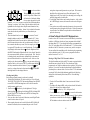
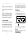
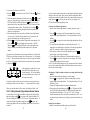
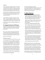
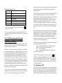
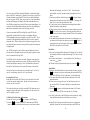
7.1 Sectioning the Layout
Even though blocking is not required for train operation with DCC,
sectioning the layout may be indicated:
1. To provide additional power to operate more locomotives than one power
supply can handle. For example a 5 amp booster & power supply will
operate between 6 & 10 average N-scale locos & between 4 & 6 HO locos.
2. To prevent total layout shutdown when shorts occur in any given section.
If a short occurs in one section, only that section shuts down, the rest of the
SECTION 1
SECTION 2
SECTION 3
DCC
DCC
C
When the DT100 is connected to a powered LocoNet, all of its power
requirements come from LocoNet & the battery is not used. When LocoNet is
powered down in sleep mode, the DT100 draws its power requirements from
its internal battery or keep-alive power tapped from a LocoNet connection.
C
6.2 Batteries
your power busses & feeders are capable of carrying the continuous full
load current of a booster to any connected area of the layout.
Once you have checked out your wiring for its current capacity be sure to
test that you can reliably shut down the booster with any short circuit fault at
any location on the track work. With Digitrax boosters audio warnings or
beeps were included to make this very easy. Simply move around the layout
& place a short across the tracks, & be sure that you hear the booster beep &
shutdown every time the short is sustained for at least 1/2 second. If the
booster does not reliably see the short you need to review the wiring &
connections until this is true.
D
DB100 & DCS100 are designed to accept either 50Hz or 60Hz AC low
voltage input power as well as DC.
7.0 Track Wiring Considerations
Early proponents of DCC touted the fact that you can hook up your railroad
with just two wires. While this is technically correct, there are some issues
that need clarification. You should have feeders to each rail approximately
every 6 feet or so from the power bus. The general rule is, "If your trains will
run on your track with regular DC then they will run on DCC." Unless you
need to section your layout for added power, the only gaps you need are for
hard shorts like reverse loops & uninsulated frogs. If you are already wired
for block control, you probably don't need to rewire. Just open all your blocks
so that the entire track has power & you are ready to go. If you are using
common rail wiring & need to section your layout, you will need double gaps
to separate the sections.
Remember, no matter how you control your trains, you should always use
safe wiring practices. In particular be aware that the multiple locomotive
capability of Command Control means that you can have many locomotives
running in a single area of the layout. For this reason, to fully upgrade your
wiring for maximum locomotive operations, you will need to ensure that all
DCC
BOOSTER
DCC
BOOSTER
layout keeps operating.
To section the layout you will connect additional boosters & power supplies.
To do this, connect the DB100's SYNC & GROUND terminals, with a short
length of wire & set the
Mode switch to RUN to set up the DB100 as a
booster when it is initially powered up. Connect to other DB100’s on
LocoNet via either LocoNet Port A or B using regular 6 conductor RJ12
extension cables. Note that the “Grounds” of all Boosters should be
connected together with 18 gauge wire. Also connect this common
"Booster ground" to the short GREEN ground wire at the side of any
DCS100 in the system.
Note: The DCS100 is not designed for current sharing and should not be
used in parallel with any other DCC booster.
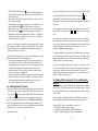
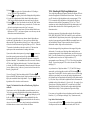
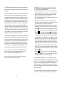
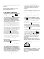
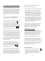
7.2 Reverse Section Wiring
25
DCC
COMMAND
STATION
26
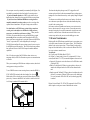
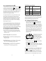
You can operate reverse loops manually or automatically with Digitrax. You
must double gap (completely isolate) both ends of the reversing section.
If you choose manual operation use a DPDT toggle switch or relay to
handle the polarity change as the loco enters & leaves the reversing section.
If you choose to use an additional DB100 auto reversing booster to
completely automate the reversing section, power the reverse loop with a
separate booster & transformer. Set up the reversing section as follows:
You should not have a DCS100's booster section driving a normal non
reversing track section adjacent to a DB100a that is being used as an
autoreverser, you should set up the boosters as follows. When you add a
DCS100 to your system with auto reversing, use the DB100a as a regular
non-reversing booster on a mainline section & configure the DCS100's
booster as the auto reversing booster by setting the Option switch OPSW03 to
"closed," as per section 24.0. In this configuration you are using the
DCS100's booster configured for auto reversing to power the reverse section
& the DB100a to power the main line. This will avoid any booster problems
that could occur because of the DCS100's improved automatic shutdown
capabilities.
Note: If the booster section of the DCS100 has a short circuit or over
temperature fault, the DCS100 will continue to operate as a command station
on LocoNet.
Where you are running two DB100 boosters in adjacent sections, the rules for
setting up auto reversing are as follows:
To use a DB100 booster as an auto reversing booster, connect the DB100's s,
SYNC & GROUND terminals, with a short length of wire & set the
Mode switch to P/R to select the auto reverse mode when the unit is initially
powered up. Connect to other DB100’s on LocoNet via either LocoNet Port
A or B using 6 conductor RJ12 extension cables.
DC
Note that when the polarity change occurs, DCC equipped locos will
continue at the speed & in the direction commanded but any analog engines
running will reverse direction because they see the polarity change & respond
to it.
Two boosters are needed to perform the auto reverse function. One booster
acts as the master system phase reference & the other handles the polarity
reversal for the reversing section.
One booster can be used to handle more than one reverse section at a time
however, the unit can only fix one gap at a time. If more than one train is
entering or leaving the reverse sections connected to a single booster at the
same time, a short will occur. More than one train can be in the reverse
section/s at any time but, only one can cross the double gaps at a time.
7.3 Bi color Track Indicators
Hooking up Bi-color LED indicators around the layout is a convenient way to
see the power status of sections of the layout at a glance. The LED indicates
whether a track section is powered up, if "Zero-stretching" Analog mode is
being used & its local direction, & can even be used to indicate if the GAPS
in a reverse section are matched or not.
You will need:
One 2 lead bi-color LED (Radio Shack #276-012)
One "ballast" or "current setting" resistor. We recommend a 1K 1/4 watt
resistor (Radio Shack #271-1321) for reasonable brightness & current levels.
•Connect the 1K resistor in series with either one of the LED leads to make
a "ballasted" LED.
•With the 2 leaded bi-color LED there is no strict polarity to observe, the
emitted color will depend on how the LED leads are connected to the
track.
•Simply connect the "ballasted" LED across the track to indicate the track is
powered. If you connect a "ballasted" LED across one of the double gaps
of a reverse section the LED will be OFF (not lit) when the gap polarity
is matched.
Digitrax Universal Panels, UP1, UP2 & UP3 incorporate bi-color LED's to
make it simple to see the power status of individual track sections.
C
DOUBLE
GAP
DCC
DOUBLE
GAP
DCC BOOSTER
AUTO
REVERSER
DCC
COMMAND
STATION
27
28
8.0 LocoNet Wiring Components
9.0 DCS100 Command Station/Booster
SOURCE OF RJ12 COMPONENTS
Many Digitrax Authorized Dealers carry the RJ12 components you need for hooking
up your LocoNet wiring. You can also check with the local telephone supply company
or Radio Shack. If you can't find the components you need locally, we recommend
DIGIKEY. The RJ12 is the 6 pin version of the RJ11 connector with all 6 pins loaded
with conductors. This is the connector Digitrax uses for LocoNet & the Challenger
throttle bus.
DIGIKEY Phone #1(800) DigiKey (1(800)344-4539).
They accept VISA/MASTERCARD, & will ship UPS/FEDEX.
Suggested parts & Digikey part #'s
Cable Couplers & Wall plates
Part Number
Description
048-0051-ND
6 Wire Adapter (1M2F)
048-0056-ND
Fem Coupler, Crossed
048-0060-ND
Dual RJ12 Wall Plate
CABLES with RJ12 plugs already on both ends
Part Number
Description
H2662-07-ND
7' CABLE W/PLUGS,BLACK
H2662-14-ND
14' CABLE W/PLUGS, BLACK
H2662-25-ND
25' CABLE W/PLUGS, BLACK.
If you are wiring the throttle bus for Challenger use, be sure that all pins are
connected in the same order when connecting to a wall plate as they are when
connecting to a DB100 command station/booster. If you are only using the bus for
LocoNet you need not worry about this, since LocoNet was designed to work for
either cable connection orientation. Note that a Challenger throttle bus can simply
be upgraded to LocoNet throttle network with no modifications. To use existing
CT4's or CTX/CTY's on the full digital LocoNet you will need a CT4 LocoNet
adapter, which will be available from Digitrax in the future.
9.1 DCS100 Connections & Configuration Controls
The Digitrax Universal Panels UP-1, UP-2 & UP-3 provide simple plug & play
alternatives to wiring RJ12 phone jacks around the layout. The UP-3 is shown in the
Chief Hook Up Diagram, (Diagram2). This fascia mounted panel provides two RJ12
jacks & a "Track Status" indicator. The back of the panel provides 2 RJ12 jacks for
daisy chaining from one Universal Panel to the next & keep alive jack capability.
Rather than wiring each outlet you simply use 6 conductor phone wire with male
plugs on each end to make the connection from one Universal panel to the next. UP-2
provides two 1/4" stereo jacks in front & two RJ12 jacks in back. UP-1 provides two
RJ12's, one 5 pin DIN & one 1/4" stereo jack in front & three RJ12's, back. Other
LocoNet devices such as the DS54 can also be plugged into LocoNet via the Universal
Panels. For more information, contact your local dealer.
29
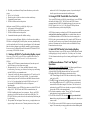
The diagram above shows the front panel of the DCS100 combined LocoNet
Command Station & Booster.
POWER IN, PROG A/B, RAIL A/B Connections: The left side terminal
block has 3 sets of connections:
a) The two “POWER IN” terminals should be connected to the power supply
or transformer you are using. See section 6.1 for information about suitable
power sources.
b) The two “PROG A/B" terminals are connected to a separate programming
track for service mode decoder programming. This can also be connected
to the "Rail Sync" lines on another DB100 booster if you wish to use the
Brake Generator feature. If you are interested in this feature, contact
Digitrax for an application note that covers this.
c) The two “RAIL A/B” terminals should be connected to the section of the
layout that you wish to drive with the DCS100's booster section.
LocoNet A/B Connections: The center section of the DCS100 has two RJ12
style Telco jacks for connections to LocoNetTM devices such as throttles,
sensors, extra boosters, computers and other LocoNet devices. You can use
either or both of the LocoNet A or B ports, since they are wired in parallel.
Scale Switch: This controls the nominal track voltage that the DCS100
booster section puts on the rails. We recommend using the N scale setting for
most operations. The typical factory settings for scale voltages are
approximately: N=12V, HO=14V, O/G=20V. The DCS100 also has an
internal user adjustment for these track voltages, see following.
30
DCS100 track voltage fine tuning: Small YELLOW trimmer/adjuster
behind the LocoNet B port & Scale switch can be used to fine tune the booster
track voltage. You will need to open the DCS100 case & use a small phillips
or 3/32" blade screwdriver to turn this potentiometer. See section 9.4 for how
to open the DCS100's case. When working inside the DCS100's case, be
careful to avoid disturbing any components other than the ones you are
working on. Measure the DC voltage (unloaded) from either track terminal
to the GREEN ground wire on the case. This measured DC voltage
multiplied by 2 is approximately the digital track voltage when the analog
channel "00" is at 0 speed. Turn the trimmer pot clockwise to increase the
scale setting voltage & counter clockwise to decrease the voltage.
We recommend that you use the lowest voltage setting that will do the job for
your application.
Mode Switch: This is a primary control for the running & configuration
of the DCS100. The 3 settings are:
• RUN position is for normal operations.
• OP position can be selected to allow a DT100 or DT200 throttle
access to the Option Switches for unit customization. see section
24.0
• SLEEP position is used to shutdown the system and to power down the
attached throttles and generate keep alive power for the throttles.
9.2 DCS100 Indicators
The DCS100 has a number of LEDs that give a visible indication of how it is
operating.
"POWER ON"
This GREEN indicator is ON when Input power is applied to the DCS100.
"TRACK STATUS"
"NET"
This is a diagnostic RED indicator that gives information about what the
DCS100 is seeing on LocoNet & how it is related to operations. In a correctly
wired operating layout this indicator will be ON and it will flicker off any
time a good LocoNet message is seen by the DCS100. Look for the following
characteristic blinking patterns on the NET indicator when you are using
your DCS100.
A) Solid RED=LocoNet OK
B) RED with Blink off=DCS100 has a valid LocoNet message
C) Steady OFF=DCS100 sees a short circuit on LocoNet
D) OFF pulsing on every 1/2 second=DCS100 is in "option" mode see section
24.0.
E) OFF pulsing on every 1 second=DCS100 is "sleeping" LocoNet.
"CONFIG"
This green indicator is used to indicate the Primary operating mode of the
DCS100. This indicator should be steady green winking off briefly once
every 4 seconds. This indicates Config setup OPSW05 is correct. If you see 8
winks every 4 seconds, then we recommend that you change OPSW05 to
"closed." The DCS100 will operate correctly in either case.
If this green indicator is mainly off then OPSW01 is incorrectly set to
"closed" and OPSW01 must be changed back to the default "thrown." See
24.0 for more information about Config Set up.
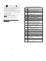
9.3 DCS100 Audible Sounds & Their Meanings
The DCS100 emits a number of beeps & clicks as warnings and diagnostic
tools that allow you to de-bug a number of conditions.
Any group of less than 3 closely spaced beeps are not used as a specific
warning. The meanings of the various sounds your DCS100 might make are
outlined on the following page.
This Bi-colored indicator is lit when there is voltage on the Rail A & Rail B
terminals of the DCS100. The shade of color is typically ORANGE for
normal DCC operations.
"OVERTEMP" or "SHUTDOWN"
This RED indicator shows that the DCS100 Booster is shutdown & is not
driving the rails. This can be caused by several situations: the track output
may have been turned off by a user, the track may be shorted, or the DCS100
may be overheating,. On some DCS100's this indicator is labeled "OVER
TEMP" and on others it is labeled "SHUT DOWN."
31
32
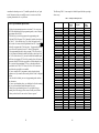
Audible
Feedback
3 Beeps
4 Beeps
5 Beeps
6 Beeps
7 Beeps
8 Beeps
9 Beeps
16 Beeps
Continuous
soft clicks
What the sounds mean to you.
A loco address has just been purged due to non-use. This is
informational only. Refer to the DCS100 Option setup,
section 24.0, to customize the loco purging operation.
Route nesting error or too many entries cascaded. You
should review the route or switch number that was issued.
Determine whether any part of this route refers to or "loops
back" on itself, or whether you have too many switch
actions. The DCS100 can support up to 120 sequential
switch actuations when any route is activated & assembled.
Booster short circuit shutdown
Command station already present in system (bad master)
condition detected. This indicates the DCS100 is being
powered up into an active LocoNet that already has an
active Command Station operating. The DCS100 will
simply become a booster in this situation.
DCS100 CMOS Battery low condition. Battery needs to be
replaced soon. See section 7.3 below for battery change
instructions.
Memory ECC/ checksum fail. This indicates that the local
CMOS memory has been corrupted & has been reset
automatically.
Transmit failure of DCS100. This indicates that there is a
device blocking proper message action on LocoNet.
Software time-out failure. This indicates that the DCS100
has had a hiccup. No action is required, the unit will
resume operation.
Low input power supply voltage. If the DCS100 input
voltage falls below about 9.5V DC or 8V AC when it is
operating, the unit will emit a series of continuous soft
clicks until the low voltage condition corrected.
1) Remove the DCS100 input power & disconnect all DCS100 leads.
2) To open the DCS100 case: Remove the two screws on the top & bottom of
each side of the case. Slide the gray front panel off the DCS100. As long
as you do not make any modifications or leave any loose parts inside the
DCS100 you will not affect your warranty coverage!
3) Locate the empty coin cell holder on the upper PC board at the top left of
the unit. There are 2 battery holders & it does not matter which holder has
a good battery in it.
4) Slide a NEW CR2032 style 20mm diameter 3V lithium coin cell in
EMPTY holder. This will ensure the 100% continuity of memory, since
this allows a "hot swap" even without any external power applied. Note
that the coin cell battery + terminal will be visible on the upper side when
it is in the holder correctly. The unit has reverse polarity rotation & the
two coin cells are isolated from each other.
5) Remove the old battery from the other holder & discard it. Be sure not to
short the +ve arm at the top of the holder to the metal case or any PC
board connection.
6) Reassemble the DCS100 case. Be sure that you don't leave any loose parts
inside.
7) Reconnect the DCS100 & be sure that you do not get 7 beeps when
external power is restored.
Sustained track short circuits on the track section connected to the DCS100
Rail A/B terminals, will cause the unit to beep 5 times & turn off its local
Booster track output. The RED "SHUT DOWN" or "OVER TEMP" light will
be on to indicate this. Note you can lengthen the short circuit duration
needed to shutdown the DCS100, by making OPSW#18 to the "closed" or "c"
position (refer to section 24.0). This will make the DCS100 booster tolerate
longer shorts, like those caused by pilot trucks crossing live switch frogs. Be
sure that your layout wiring & locomotives can handle these longer short
circuits and only use this adjustment if you are satisfied it will work properly
on your layout and not cause damage to your locos or wiring.
9.4 DCS100 CMOS Battery Warning & Replacement
If you get 7 beeps when power is first applied you need a new CMOS memory
backup battery. While this beeping indicates that the battery should be
replaced, your memory integrity is still fine. The DCS100 will still operate,
even if this battery is not present, but all your memory settings & option
switch settings will not be remembered when the DCS100 is powered down.
To replace CMOS battery without losing any memory settings
33
34
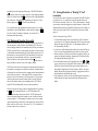
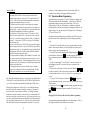
DT100 Throttle Diagram
10.0 DT100 LocoNet Throttle Control Panel
10.1 General Color Codes
The DT100 control panel is color coded according to how the keys are used.
GREEN keys & indicators are for loco speed & direction control.
RED key is "Run/Stop." This is so you can't miss it in case of emergency.
BLUE keys are related to function control. When the function mode is
active, the GREEN keys in the bottom row take on the BLUE meanings
F3/F7, F1 /F5, F2 /F6, F4/F8.
10.2 The Left & Right Throttle Knobs
The Throttle Knobs on the DT100 are actually "encoders." They give very
smooth, fine speed control. In 128 speed step mode it takes several complete
turns of the knob to go from stop to full speed. When you select a locomotive
that is moving & set it on a Throttle Knob, the Throttle continues to run the
locomotive regardless of the position of the Knob.
You can customize the tracking characteristics of these knobs for either
"straight line" or "ballistic" tracking. With "straight line" tracking each
movement of the knob causes a fixed rate of change in the display. With
"ballistic" tracking, the faster you move the throttle knob, the faster the data
changes in the throttle. Your DT100 was shipped with "ballistic tracking" as
the default setting. To change your throttle to "straight line" tracking see
DT100 option setup in section 20.0.
10.3
Direction Indicators
RED=Loco in Reverse
GREEN=Loco in Forward
Flashing=Throttle Active in Display
Both Flashing ORANGE= System is in "Stop" with track power ON
Both Solid ORANGE = System Track power is OFF.
10.4
Program Mode Indicator
Indicates that this DT100 throttle is in the programming mode. When this
mode is active the throttle knobs & keys will not control any selected
locomotives but allow you to use either the Service mode programmer in the
DCS100 or perform operations mode programming on the mainline. See
section 21.0 for complete programming instructions.
35
36
10.5
OFF
Blinking
RED
Steady
RED
Address Mode Indicator
Indicates that the display active throttle in the DT100 is
controlling a 2 digit short address.
Indicates that the display active throttle is controlling an aliased 4
digit address that is aliased to a 2 digit address decoder.
Indicates that the display active throttle is controlling a 4 digit
long address (or EPF or 14 bit address).
10.6 LCD Display
The DT100's LCD display is used to display several different types of
information to the operator.
Current Operational Mode of the DT100: The three small mode indicators
across the top of the LCD indicate whether you are in MU
(multiple unit
or consist mode), LOCO
(regular locomotive operations mode) or
(turnout control mode).
SWITCH
Only one of these indicators will be lit at
any time. The DT100 automatically
defaults to the LOCO mode & will return to
this mode if you change to another
operational mode & don't do anything within about 6 seconds. Use the
key to toggle among these operational modes
The numbers & letters in the LCD screen have different meanings depending
on the mode the DT100 is in & the functions you are executing. They may be
flashing or not. A flashing display is usually a prompt. All of these displays
& their meanings are described later in this manual.
The colon in the middle of the display is flashing when the Fast clock is
being displayed. No colon will be displayed when you are working with 4
digit addresses. A steady colon will be displayed when you are working
with 2 digit short addresses and when you are status editing.
10.7
Run/Stop
When this key is used by itself it can be set up to operate in one of two ways.
This set up is part of your throttle option set up when you initially power up
each throttle and each DT100 throttle can be set up differently.
a) The default Local Run/Stop allows you to stop only the addresses under
is pressed for 1 sec.
control of your throttle when just
b) Global Run/Stop allows you to stop the entire layout by pressing just
for about 1 second. Press again to toggle between STOP & RUN.
37
Other special uses for Run/Stop when used in conjunction with other keys are
described in other sections of this manual. This is the same way that DT200's
operate.
10.8
Select/Set
Used for selecting & setting loco addresses to the throttles. When the DT100
is address selecting or in "browse" mode the LOCO mode indicator will be
blinking. If there are steady 4 digits in the display with no colon on you are
selecting a 4 digit address. The EXP indicator
will also be lit & indicate
which type of 4 digit address is being selected. A steady EXP
in this
case means 4 digit long addressing and a blinking EXP
means aliased 4
digit addressing.
If the left 2 digits are flashing along with the LOCO indicator & there is a
colon in the middle of the display then a 2 digit short address is being
browsed.
This key is also used in other modes to select or complete an operation.
10.9
Mode/Dispatch/Display
Mode: Press
to move from one operational mode to another. LOCO is
the DT100's default mode since most of the time you are running locos. Press
to change to SWITCH then to MU then back to LOCO.
Dispatch: To Dispatch or offer a locomotive you have set up on a DT100 to a
BT-2 limited throttle, press this key while in Select Address mode.
Display: In programming mode this also can be used to read back or
"DISPlay" a CV value from a decoder on the DCS100's Service mode
programming track. See section 21.2 for details.
10.10
Function/F0/Light Control
Press once to enter Function Mode. The display shows "Fn:oo" with the oo
flashing to indicate that you must choose which function you wish to toggle.
Press
again to toggle the directional lights on or off. OR, press the key
above F1, F2, F3 or F4 to toggle any of those functions that are available in
your loco. Function 2 is a special key because it is non latching, this allows
you to activate a function while the key is held down & deactivate it when the
key is released. This makes it easy to simulate blowing a horn.
Press & hold the
key while pressing the key above F5, F6, F7, F8 to toggle
functions 5-8 on & off.
38
In Edit & Programming modes
choices.
is also used to cycle among several
10.11 Function 1-8 Keys
Active when in function mode. Use the keys above these designations to
access the various decoder functions. F2 is non latching. See section 10.10
for more information about using these keys.
10.12
&
Arrows
Left & Right Throttle Direction Change
Changes the direction of the loco on the related throttle. The
key
changes direction of the address on the "R" or Right Throttle. The
key
changes direction of the address on the "L" or Left Throttle.
Also used to select the position to which you want to set a switch or turnout:
c=closed
t=thrown
These keys are also used by the various system editors to control data entries.
10.13 Up/Add & Down/Delete Arrows
Use to browse addresses & increase/decrease speed. Use to MU-Link & MUUnlink locos from consists. These keys are also used when you are using
various system editors.
These +/- keys can be configured to be repeating so that if you hold a key
down it will repeat until you release the key. This is the normal default when
the "ballistic knob" mode is selected as the Option setup for this throttle, see
section 20.0.
11.0 DT100: Major System Modes
The DT100's MAJOR mode changes are controlled when the DT100 is
connected to LocoNet by using the
key in conjunction with other keys as
described below.
&
When track power is on, press the
keys simultaneously to have the
DCS100 or master Command station turn OFF track power & stop generating
DCC packets. This will turn off the track power from all boosters.
11.3 Stop Mode
If the track power is on and trains are running the keys
the system go to STOP, and all trains will stop. Pressing
layout is in STOP will change it back to RUN.
Section 10.7 discusses the operation of the
&
will make
while the
key when used alone.
When the system is in STOP Mode both of the direction indicators will
blink ORANGE. In this state there is power to the track but all locomotives
are stopped.
11.4 Programming Mode
Any DT100 can program locomotive decoders by accessing the network
programmer of the DCS100. To enter Programming Mode, press the
&
keys simultaneously. Section 21.0 Decoder Programming &
Configuration gives complete programming instructions.
Note: DT200's are not designed to access the Network programming of the
DCS100.
11.5 DT100 Unit Reset
Press
,
&
keys simultaneously. This three key-stroke input will
force the DT100 to reset itself and will allow you to redefine the Primary &
Secondary Options for the throttle. Removing & replacing the battery also
causes the DT100 to reset. If you are using RESET to reconfigure the DT100
throttle options it is best to first release any addresses being controlled by this
throttle.
11.1 Track Power On Mode
When track power is off, press the
&
keys simultaneously to have the
DCS100 or master command station turn on the track power & go through
&
will
power up sequencing. Once track power is on, then pressing
cause the system toggle between RUN and STOP.
11.2 Track Power Off Mode
39
&
40
12.0 LOCO Mode: Running Trains
LOCO mode is the default mode for the DT100 because it is the mode you use
to run the trains. If you change to SWITCH or MU mode & don't do
anything, the unit will default back to LOCO mode in about 6 seconds.
If a throttle has a locomotive selected & under its control, its associated
direction indicator will be GREEN if the loco's direction is forward & RED
if its direction is reverse. In addition, if the direction indicator is flashing
it means the associated throttle's locomotive information is currently showing
in the display, meaning the Address & Speed in the display are related to this
throttle. For example: if the on the right side of the DT100 is flashing
RED, this means that the ADDRESS & % SPEED in the display are for the
loco that is currently being run by the Right Throttle Knob & that
locomotive's direction is reverse.
The RED EXP indicator
shows whether the locomotive address this
throttle is controlling is a 2 digit short address, an aliased 4 digit address or a
4 digit long address.
To display the information for the throttle not currently in the display, turn
the Throttle Knob not currently in the display. If you change the direction of
the loco not currently displayed, the display will also change to that Throttle
Knob & make it’s display active.
12.1 The Select Message
If a Throttle Knob does NOT have a locomotive selected when you try to
make it display its information with its knob or direction change arrow, the
display will show "SE:L-". This means that there is no active loco on the
throttle you tried to display & that you need to press, browse to the loco
address you want to run & set it to that throttle by pressing
again before
you can use it.
12.2 Two Digit Short Address & % Speed Display
When you have a loco with a 2 digit short address the EXP indicator
is
off & the numbers to the left of the colon & above the word "ADDRESS,"
are the address of the locomotive & the numbers to the right of the : & above
the words "% SPEED" are the % speed for the throttle currently displayed.
The speed is shown as a % of full speed & is NOT actual speed step codes
sent to the decoders in the locomotives. Note: For addresses above 99 please
refer to Table I below to translate the mixed mode hexadecimal value that
shows in the display for addresses above 99.
41
Table I: Translation Table for Decimal to Mixed Mode Hexadecimal
Numbers for Loco & Switch Addresses Above 99.
DEC MM
DEC MM DEC MM
0-99 0-99
100
A0
110
b0
120 c0
101
A1
111
b1
121 c1
102
A2
112
b2
122 c2
103
A3
113
b3
123 c3
104
A4
114
b4
124 c4
105
A5
115
b5
125 c5
106
A6
116
b6
126 c6
107
A7
117
b7
127 c7
108
A8
118
b8
109
A9
119
b9
12.3 Locomotive Speed Control
To control the speed of a locomotive, just turn the throttle knob that is set to
the locomotive whose speed you want to change. If the throttle was not
already active in the display it will now become "display active" & the display
will show its address & current speed commanded. Alternately, speed can be
increased & decreased by using the
and
keys.
A 2 digit short address will show the address on the left side & the current
speed on the right side, separated by a steady colon .
If you change the speed of a 4 digit address loco, then the new speed, xx will
flash up on the display as "SP:xx" & the display will return to the steady 4
digit address with no colon & the LOCO flag on.
If a sub-element in a consist with a 2 digit short address, aa, is selected in a
throttle & you try to change its speed the display will change to "aa:cn" & the
"cn" digits in the speed side show that you cannot directly change the speed
or direction of this loco since it is in a consist. You can however go ahead &
modify its functions such as lights, etc.
If the consisted loco has a 4 digit address, the EXP indicator
will not
light up, but the display will flash up "-cn-" & then return to the 4 digit
address display.
42
12.4 Locomotive Direction Control
To change the direction of a locomotive, just press the direction arrow
for
the address set to the Right Throttle Knob or
for the address set to the
Left Hand Throttle. The direction indicator beside that throttle will change
color to indicate the new direction (RED for reverse or GREEN for forward).
If the throttle was not "display active" when you changed direction, its
information will also now appear in the display.
If you change direction while a loco is moving it will slow down to 0 speed
and then speed up to the commanded speed according to the decoder's
programmed deceleration and acceleration characteristics. Since it is more
prototypical to stop the loco before changing directions you will probably
want to close the throttle to 0 speed & stop the loco before commanding a
direction change but, it's up to you.
If you have programmed the decoder with a non-zero deceleration rate that
matches the scale effect of braking the train, then you can simply command
an instant reverse of direction, and the system and decoder will simulate
braking by causing the locomotive slow down at the programmed deceleration
rate, stop & accelerate again at the programmed acceleration rate.
12.5 Selecting the Locomotives You Want To Run
With the DCS100 there are four options for addressing and programming
locomotives. You can use these four addressing modes at any time in any
combination you choose.
Address "00" Analog Address: For locos without decoders
2 Digit Short Addressing: Also called 7-bit or short addressing can be used
with any DCC decoder
Aliased 4 Digit Addressing: Assigns a 4 digit alias to a 2 digit short address
decoder. Gives you 4 digit addressing with all DCC decoders
4 Digit Long Addressing: Also called 14-bit, EPF, or long addressing can
be used with any DCC EPF decoder that supports this feature.
The DCS100 address range looks like this:
Address in
EXP
What these addresses represent
DT100 Display
indicator
0001 to 9980
RED flash
Alias Roster for Aliased 2 Digit
Short Addresses
00:
off
Analog Address
01: to c7: (127)
off
2 Digit Short Address Range
0128 to 9980
RED steady 4 Digit Long Address Range
This addressing scheme provides complete backward compatibility with all
existing DCC decoders & does not force you to replace any decoders while
allowing four digit addressing for any decoder on the layout.
12.5.1 Selecting A 2 Digit Short Address
1. Turn the throttle knob you wish to use about 1/8 turn to make it the
"display active" throttle. Press the
key to enter "address select"
mode. The left hand side of the display that shows the short address 2
digits will flash to prompt you to choose an address. The right-hand side
of the display shows various status codes as you "browse" 2 digit short
addresses. The meanings of these codes are detailed in the section 16.0
status edit section. Generally you don't need to worry about these codes
since the system automatically uses them transparently to most users.
They give you a convenient & valuable insight as to how locomotives are
operating on the layout.
This display shows locomotive address
21 selected but not set, since the
address 2 digits are flashing. Notice
the status "12" indicates this address is
common, 14 speed step mode.
2. Turn either throttle knob or use the
&
keys to browse through
the addresses to the one you want to run.
3. Press the
key again to SET that 2 digit short address. If the address
request is successful, the display will show the locomotive information at
the speed & direction the system has remembered it.
If you try to access a loco address that is active on another throttle, when you
press
to set the address, the display will change back to SE:L- & the
throttle direction indicator will not light up. The address SET request
failed because the LocoNet system does not allow you to select a locomotive
address that is active or "in-use" on another throttle anywhere else on the
43
44
system. This is true even if the loco address is being used by a completely
different throttle or even a remote computer hooked up to the system! At this
point just press
again & scan for a different loco address that is not "in
use."
In certain cases you can override this security interlock & "steal" an "in-use"
locomotive. See section 13.1 for details, & use this facility wisely.
When you request "address select" on a "display active" throttle by pressing
, the current displayed locomotive will immediately be made common or
released to the system for anyone to select. Once you have entered "address
select," you can browse for another locomotive that is common, idle or new &
SET this locomotive on the throttle with another press of the
key.
Obviously, you can simply re-select the locomotive you just released when you
started "browsing," provided someone else did not select it on their throttle in
the meantime.
When you press the
key the second time to SET a locomotive address the
system makes the locomotive in-use & only your throttle has control of it.
See section 16.1 & 16.2 for notes on locomotive stealing & DT100 slot
following capability.
A new locomotive address once set on the throttle becomes in-use at speed 0,
forward direction & all functions off.
The only way to modify the speed & direction of consisted or MU'd
locomotives is to select the address of the TOP of the consist. We call the
"key" locomotive that other locomotives are consisted TO, the TOP
locomotive because it does not need to be in any particular physical order in
the consist. The TOP locomotive address controls the speed & direction of all
locomotives consisted to it by the MU function. See section 19.0.
If during "address select" mode there is no input for the 6 second time-out
time, the DT100 will abort the selection process & default back to LOCO
mode with the throttle now inactive. This clears the locomotive that was in
the throttle & makes it common or accessible to the rest of the system.
Note: If the right hand side of the status display shows "FF" during address
selection, this means that the command station has reached the limit of in-use
& common locomotives that it can refresh at one time. The DCS100 is
shipped with OPSW#44 at its default setting of "t" & 22 slots, since refresh
frequency is improved if you are not using more than 22 running locos.
When you see the "FF" message you have two options
45
1. Free up some refresh slots by making sure any locomotives you are not
using are not selected on any throttle ("common" at speed 0).
2. If you need to use more than 22 slots you can change the DCS100
OPSW#44 to "c." This increases the DCS100's slot refresh capacity to
approximately 120 active locos with any available address. If you use the
expanded 120 slots, note that some Trinary mobile decoders may behave
sluggishly. See section 24.0 for setting up the DCS100 options.
12.5.2 Selecting An Aliased 4 Digit Address From the
Alias Roster
For accessing the aliased 4 digit address mode refer to lower section of
Diagram 4.
Aliased 4 digit address mode is a very powerful way for the system to allow 2
digit short address decoders to be selected from the system Alias Roster &
then operated as 4 digit addresses. This allows any decoder to run with 4
digit address, even if it does not support the 4 digit long address format. You
can even assign the Analog (Conventional address 00) to a 4 digit number.
Arnold decoders and Motorola Trinary/Marklin "AC digital" decoders can
also be aliased and run with a 4 digit address!
The Alias Roster is a database of 4 digit numbers that are matched to 2 digit
short addresses. The Alias roster defines all the power units you choose to
operate this way. The Roster is stored in the DCS100. The DCS100
remembers the Alias Roster even if the system is powered down between
sessions. It is very easy to update or edit this Roster. The Roster is
conveniently sorted in numerical order, which makes browsing for an address
very easy. Because only the active aliased 4 digit addresses are included in
the Roster it is an uncluttered way to remind yourself of the actual current
locomotives usable on the layout.
To view the current Alias Roster press
and turn either throttle knob to the
left and once you browse below address "00" you will see the aliased
addresses that are active in the system. When you enter this Alias address
area, the DT100 will check that the system supports Aliases. If the system
supports aliases, the EXP indicator
will start blinking & the DT100 will
beep and allow you to browse the aliased 4 digit address roster (below address
00). If there are no current aliased 4 digit addresses in the Alias roster you
will see "- - - -" in your display as you browse the roster.
46
To access the Alias Roster on your DT100:
1) Press the
key to enter browse mode. The LOCO indicator will begin
to blink.
2) Turn either throttle knob counter-clockwise or use the
or
keys until
you get to 2 digit address 00. Continue one more step below "00" and the
DT100 will beep & the RED EXP indicator
will begin to flash to
indicate that you have entered the alias roster. The LCD screen will show
a 4 digit number without a colon. The blinking LOCO indicator
lets
you know that you are browsing through the aliased 4-digit addresses
already set up in the Roster.
3) Browse through the Alias roster until you find the aliased 4 digit address
you want to run. The aliased 4 digit addresses set up in the roster will
appear in descending order with the largest one first.
4) Press the
key to select this aliased 4 digit address to your throttle. The
LOCO indicator
will stop blinking and become steady. The EXP
indicator
will be blinking RED to show the 4 digit number in the
display is actually an aliased 4 digit address linked to a 2 digit short
address.
If you pause at an Alias address entry for longer than about 1 second then the
DT100 screen will change to display the Loco's status code "cc" in the display
as "St:cc". This status number is the same as used in the 2 digit short address
mode (see 16.0 for status code list) & can be status edited in the same manner
by pressing the
key.
In this example the 3 means the Loco is inuse and the DT100 will not allow you to
select this normally. The 2 means that this
loco is being handled by the system as a 14
step decoder on the track.
If you browse down the Alias roster or list & come to an empty Alias entry,
the display will show a line of 4 dashes "----" to indicate this entry is empty.
When you reach the end of the Alias entries, the display will show "-end".
12.5.3 Editing Aliased 4 Digit Address Roster Entries
To read back the actual 2 digit short address assigned to the aliased 4 digit
address, simply press the
key to toggle to the 2 digit short address "aa".
This will be displayed flashing as "AL:aa" (ALias: 2 digit short address). To
return to the aliased 4 digit address simply press the
key again. The
aliased 4 digit address will now be flashing to indicate that it is now able to
be edited.
47
You can swap the display between the two digit address and aliased four digit
address as often as you wish. When you have finished reading back and/or
modifying the aliased 4 digit address or the 2 digit short address for this entry
simply press the
key to close the entry and save your changes. The
DT100 will resume browsing the alias roster.
Creating a new aliased 4 digit address:
1. Browse to any aliased 4-digit address or an empty alias roster entry "- - - ".
2. Press the
key to toggle to the 2 digit short address that is currently
assigned to the aliased 4 digit address. The 2 digit short address will be
flashing.
3. Press the
key to toggle back to the aliased 4 digit address that will now
be flashing.
4. To edit the aliased 4 digit address, use the left throttle knob ("L") to
change the two left hand digits in increments of 100 and the right throttle
knob ("R") to change the right two digits by increments of 1.
5. When you have chosen a new aliased 4 digit address press the
key
again to toggle to the 2 digit short address.
6. Use the throttle knobs to change the 2 digit short address as desired
7. Press the
key to close the entry and save your changes. The DT100
will resume browsing the alias roster again.
NOTE: The aliased 4 digit address entry you started with will not be altered
since it will not match the modified aliased 4 digit address when you closed
the edit and saved the changes.
Changing the 2 digit short address aliased to an existing aliased four digit
address.
1. Browse to the aliased 4-digit address you wish to change.
2. Press the
key to toggle to the 2 digit short address that is currently
assigned to the aliased 4 digit address. The 2 digit short address "aa" will
be flashing "AL:aa".
3. Change the 2 digit short address by using the throttle knobs
key. The display will flash
4. When you have finished editing, press the
"good" (GOOD) to indicate that the DCS100 accepted the changes and
saved them to the Alias Roster. If you get "FULL" (FULL) message
instead it means that the Alias roster in the command station is full. You
can make room for another entry by deleting an existing Alias address (see
below).
Deleting an Alias address:
1) Browse to the aliased 4 digit address that you wish to delete.
48
2) Press the
key to toggle to the 2 digit short address "aa", flashing as
"AL:aa" (Aliased to 2 digit short address)
3) Press the
key to toggle to go back to the flashing aliased 4 digit address
4) Use the Left or right throttle to dial the aliased 4 digit address down to
"0000" which is invalid and marks the current roster entry for deletion.
5) Press the
key to "close" the edit mode & write back this "0000" address
which will erase the Alias address entry you started with. The Alias roster
will now be sorted again to remove this "gap" in its entries.
6) If you were freeing up an entry because a previous addition failed because
the Roster was "FULL", you can now regenerate a new alias entry since the
deletion has created room in the Roster
Note that it is permissible to have more than one aliased 4 digit addresses
with the same 2 digit short address. If you try to select an aliased 4 digit
address and the 2 digit short address is already "in-use" in the system then it
will not be selectable & its status will typically flash up as "St:3x". Where the
"3" means the decoder address is already in use & the "x" indicates what
speed step mode the command station is sending to the decoder.
If you start the address selection process by pressing the
key on an active
throttle that currently contains an aliased 4 digit address, the associated 2
digit short address will be released & marked in the system as having the 4
digit alias "embedded." (This embedded Alias will be recovered if selected by
a DT100 using 2 digit short address browsing.) If an aliased 4 digit address
is released, your DT100 will automatically return to browsing the Alias roster
for a new address to select. In this case, you won't need to re-enter the Alias
Roster by "going below 00."
If you are "browsing" 2 digit short addresses & the EXP indicator
begins to flash RED, this means that the 2 digit short address currently in the
display has an embedded aliased 4 digit address. If you press
the aliased 4
digit address will be selected to run the locomotive.
'Zapping' The Embedded Alias Address When Browsing 2 Digit Short
Addresses:
If you choose to use the 2 digit short address to run the locomotive, you can
"zap" (clear) a previously embedded aliased 4 digit address information by
pressing the
key. The EXP indicator
will stop blinking & you will
be able to select the 2 digit short address with no embedded 4 digit alias
information by pressing
. Zapping an embedded alias does not make any
changes to the alias Roster. You are simply removing the embedded alias
information that was referenced earlier from the alias Roster.
49
12.5.4 Selecting A 4 Digit Long Address Loco
To use 4 digit long addressing you must use decoders like Digitrax FX Series
decoders that support this Extended Packet Format feature. In order to run
your FX decoders in 4 digit long address mode you must program CV17 &
CV18 to contain the 4 digit long address, & also enable the 4 digit long
address mode in the decoder by programming CV29 bit 5 to 1. This is
somewhat more involved than using the aliased 4 digit address mode with 2
digit short address decoders. Refer to the Programming section 21.0 for
information on this.
Note that you cannot use 2 digit short address decoders (like the Digitrax
DH82, DH83, DH84. DN82, DN83, DN93 and DG83, most Lenz decoders,
Arnold, Marklin DC digital & many others) in the 4 digit long address mode
since they do not support this particular NMRA Recommended Practice for
the Extended Packet Format. Digitrax created the aliased 2 digit short
address mode to allow 4 digit access to these decoders.
Decoders that support 4 digit long address mode also support 2 digit short
address mode. Be sure that your 4 digit long address mode decoders are
programmed appropriately for the command station you will be using to run
them. If you take a locomotive from a layout where it is being run in 4 digit
long address mode, it must have its 2 digit short address (CV1)
reprogrammed to turn off the usage of CV17 & CV18 as 4 digit long address
decoder. You can also reprogram CV29 to achieve the same effect without
modifying CV1.
As you browse above 2 digit short address "c7" (127) the DT100 changes
automatically to 4 digit long address mode & the EXP indicator
will
change from off to steady RED. In order to make it easier to select four digit
addresses on your throttle, once you enter the four digit long address mode,
the left throttle knob will increment the left hand digits of the address number
by 100's (from 100 up to 9900) and the right throttle knob will increment the
right hand two digits of the address by 1's (from 0 to 99). For example, if you
want to browse to 4 digit long address 6587 you would use the Left Hand
Throttle Knob to dial up 65 in the left hand two digits and the Right Hand
Throttle Knob to dial up 87 in the right hand two digits in the display.
If you pause on a Long Address for more than about second, the status for this
locomotive, "xy", will flash up on the display "St:xy" (Status:status code)
Long Address Selection shortcut:
If you press down & HOLD the
key to release a loco or start the address
selection process & then turn one of the throttle knobs, the DT100 will
50
immediately enter the 4 digit long address range. The RED EXP indicator
will glow steady to let you know that you are in the 4 digit long address
range. You can then release the
key & browse for the 4 digit long address
you wish to select. When the 4 digit long address you wish to use is in the
display, simply press the
key to select it into the throttle.
You can status edit a 4 digit long address decoder the same way as a 2 digit
short address or aliased 4 digit address is status edited by pressing the
key before "setting" the address to the throttle. See section 16.0 for
information about status editing.
13.0 Walkaround Operation On LocoNet
When a DT100 detects that it is NOT connected to a powered-up LocoNet it
will enter the power saving idLE mode, & will display idLE. This occurs
when you unplug a throttle to walk around the layout. When you reconnect a
DT100 to a powered LocoNet, it automatically logs back on to the network &
verifies that the command station has an exactly matching state for any of its
throttles that were active when the DT100 was disconnected. If there is any
discrepancy, the associated throttle will not be reactivated automatically.
When your throttle is reactivated the direction indicator will be lit & the
display will show the state of the last "active display" throttle.
If a DT100 with selected in-use locomotives is disconnected from LocoNet for
more than the system purge time (about 200 seconds), the Command Station
will purge these in-use locomotives to the common state so that other throttles
can access these locomotives. If the original DT100 is reconnected after a
purge of its last in-use locomotives, it will recognize this. If the previously
in-use locos that are now common locomotives have not been selected by
other LocoNet throttles & the system command station is a DCS100, the
original DT100 will automatically re-log on to these purged locos.
13.1 Forcing A Selection, or "Stealing" A "Lost"
Locomotive
You won't be able to select a locomotive into a throttle if the DCS100 realizes
it is already "in-use." It is possible to override this interlock & force the
DT100 to select an already "in-use" loco. This is called locomotive "stealing"
& can result in two throttles logged onto a single locomotive. Because of this
multiple-throttle interaction you should be careful when you use stealing. It is
useful to use to gain control of "lost" locomotive before the system actually
purges it.
To Steal a Locomotive Using a DT100:
1. Use either throttle knob to browse to the address of the DCC locomotive
you want to steal. In 2 digit short address mode the DCC locomotive status
digits on the right will typically show "3x" indicating this address is "inuse" & not normally selectable.
1a. If you are in a 4 digit address display mode the Loco status will flash up
"St:3y" after your browsing address has been stable for at least a second.
2. Before you time-out of "browse" mode & while you still have the loco you
want to steal showing in the display, disconnect the DT100 from LocoNet.
The display should immediately go "idLE".
3. Press & hold the direction arrow for the throttle side (either
or
)
you were using in step (1) & plug the DT100 back into LocoNet. After the
DT100 beeps you can release the direction key and the throttle you are
using should be logged onto the "stolen" locomotive address. Note that a
throttles' direction key being depressed when it is plugged into LocoNet is
the authorization for only that throttle to steal.
4. Once a throttle has "stolen" a loco the slot following mode becomes active
and both throttles will update speed and direction information for the
address.
If the this is not the case, simply reselect the purged locomotives by pressing
the
key for the appropriate throttle, i.e., the DT100 throttles still
remember the locomotive that was last selected. The SET operation will
reactivate the throttle & make the locomotive in-use in exactly the state the
system remembers it. The designation of locomotives as in-use or common
ensures orderly sharing of locomotives on the layout & increases the system's
ability to run more locos at a time. See section 13.0-13.3 for a discussion of
locomotive status, in-use, common, etc.
51
52
Diagram 4: Address Selection Flow Chart
53
54
13.2 DT100 Slot Following-"Training Mode"
When a DT100 detects that a loco address that is "in-use" on one of its
throttles is being changed by another throttle or computer, it will "click"
every time it sees a remote throttle change its locomotive settings. If that
locomotive is in the display active throttle, its speed display will also show the
changes. This is called slot following. This allows two DT100's to run a
single locomotive with either throttle being able to send commands to the
loco. Both throttle displays will reflect the exact state of the locomotive. You
can use slot following as a "training mode."
A supervisor can "steal" a locomotive that is in a trainee's throttle & be able
to "look over the trainee's shoulder" or closely supervise that locomotive's
control. The supervisor can gain instant override control without having to
physically "grab" the trainee's throttle. The allows you to have unskilled
visitors operating on your layout and lets you allow them to participate and
enjoy operations without undue anxiety for either party.
Slot following also allows a PC on LocoNet to run sophisticated CTC &
routing control programs that permit the system to have automated control
over locos. The computer would be able to control speed and stop engines
automatically while letting the engineer with the throttle in his hand know
what is happening.
13.3 DCS100 Loco Purging Strategy or Time Out!
Sometimes when I plug my DT100 back in it doesn't log back on to the
engine (or engines) I was running before I unplugged. What should I do?
The DCS100 will automatically release or "Purge" locomotives from "in-use"
to "common" that are not under the control of a throttle connected to LocoNet
after about 200 seconds. This is a safety feature that allows other throttles in
the system to gain control of engines that may have been left running
unattended by an engineer.
Once a loco has been purged by the DCS100 to "common," other throttles in
the system will be able to select & control it. If this occurs & the original
DT100 is plugged back in again, it will not log back on to the purged loco
since it sees that another throttle now has that loco "in-use." If the purged
loco has not been placed "in-use" by another throttle then the original DT100
will automatically recover the purged loco when it is reconnected to LocoNet.
By setting some of the DCS100's option switches, you have several purging
options available:
1. The default is purge time=200 seconds.
55
2. Purge time can be increased to 600 seconds (OPSW13=closed)
3. Purged locos can be set to stop when purged (OPSW15=closed)
4. Purging action can be disabled completely (OPSW14=closed)
See section 24.0 for information about setting DCS100 option switches.
14.0
Controlling Lights & Functions
key once to enter the Light/Function control mode for the
1. Press the
"display active" locomotive. The display will show "Fn:oo" with the "n"
flashing to indicate that the function number of the function you wish to
change needs to be selected.
2. Once you are in the "Fn:oo" mode, use one of the 5 BLUE keys to choose
which function you want to change.
key will now select & change the
Light or "F0" function. Each time the
key is pressed while in the
"Fnoo" mode, the Light/F0 will change from OFF to ON or vice-versa. The
display will show "F0:on" (Function 0:on) for light ON & show "F0:oF"
(Function 0: off) for light OFF. This is the same for the other functions
F1, F2, F3, F4.
3. To access functions F5 through F8, press and hold the
key while
pressing the BLUE F5, F6, F7 or F8 key to toggle between on and off for
the function you choose.
You can "mix & match" & change any of the functions F0 - F8 while you are
in the "Fnoo" mode until you are satisfied with the settings & return to LOCO
mode.
To make it easier to control sound features, F2 is a non-latching function.
This means that if F2 is used to control a whistle or horn sound from the
decoder, it will only sound when F2 is held down in the "Fnoo" mode.
To return to LOCO mode you have three options:
1. Adjust either throttle knob,
2. Press the
or
key, or
3. Wait for the 6 second no-input time-out to elapse
Note that for proper light operation, you must be sure that the operating mode
(Standard 14 or Advanced 28/128 speed steps) of the decoder matches the
operating mode sent by the Command Station to that decoder. If you are
using a Digitrax or other DCC decoder that can access Advanced mode, we
recommend it be programmed to the Advanced mode, and that you run your
DT100 in the Advanced 28/128 speed step (default) mode. For other DCC
Baseline-only decoders you will need to status edit the decoder to Standard 14
56
speed step mode to have correct motor & light operation. See also Status Edit
in section 16.0-16.3.
14.1 Controlling Functions On Consisted Locos
Even though a locomotive is part of a consist, you can still access its function
outputs independently as follows
1. Press
consist.
2. Press
and browse to the address of a locomotive that is a part of
again to set the loco to your throttle.
2a. Consisted 2 digit short address. If the loco you want to change the
functions on is a 2 digit short address, the display will show "aa:cn"
(Address number:consisted) to show that locomotive address aa is part of a
consist & can't have its speed or direction changed. The throttle knob will
NOT operate & the direction indicator will be unlit. However, the
functions on this locomotive address can be modified by pressing
and
proceeding with the normal function control keystrokes outlined above!
2b. Consisted 4 digit long address. In the case of a loco with a 4 digit
address, when you press the
the second time, the throttle will display
"Se:L" (it will appear to reject the address selection). Move either throttle
knob or press either direction arrow key and "-cn-" will be displayed in the
first screen followed by a second screen with the consisted 4 digit loco
address to let you know that the loco selected is part of a consist. Press
the
key & proceed with the normal function control keystrokes outlined
above.
15.0 Dispatching Locomotives
Dispatching is a special feature incorporated in the LocoNet "language" to
meet the needs of operators that wish to enforce a strict discipline in how
engineers access locomotives during an operating session. Dispatching also
allows you to have newcomers run trains on the layout without giving them
access to the entire operation.
To dispatch a locomotive using a the DT100, press
to enter "address
select," browse to the address you want to dispatch & press
to dispatch it,
that's all there is to it! The dispatched train can be a single locomotive or a
consist that was set up by the DT100. Note that you cannot dispatch a loco
that is currently in-use.
Any LocoNet throttle with dispatch capability can take a locomotive setup in
a throttle & release it to the system as common & also specially marked as the
dispatch locomotive.
57
This specially marked Dispatch locomotive can be requested & acquired by
any BT2 "Buddy Throttle." The first BT2 in the system to press
and the
or
will take command of (or acquire) the dispatched loco on either
the Left or Right Throttle of that BT2. BT2's have no address selection
capability of their own. This is similar to how real engineers are "assigned"
trains in the prototype world.
The BT2 that acquires the dispatched locomotive/consist will pick-up the
train in exactly the state it was in when it was initially dispatched, i.e., if the
unit was moving with lights on, it will be acquired with no speed change &
continue with lights on until the acquiring BT2 commands a new setting.
The TOP locomotive in a consist or MU lashup can be Dispatched to pass
control of the entire consist to a BT2 "Buddy Throttle."
Dispatching a locomotive is also a fast & convenient way to clear a throttle
for another address selection, without having to wait for the unit time-out
back to LOCO mode. This happens when you want to swap locomotive
addresses for convenience, from one throttle side of a DT200 to the other.
There is only one Dispatch marked locomotive in the system at a time. The
Dispatch marked locomotive will be acquired by the first BT2 or DT200 to
request it and set it to their throttle.
Your BT-2 will handle all forms of addressing (2 digit short addresses, 4 digit
long addresses and 4 digit aliased addresses.)
16.0 Decoder Status
The Digitrax system assigns various status codes to each locomotive in the
system at any given time. Status codes are made up of two digits and display
in the form "aa:xy" for 2 digit addresses and "St:xy" for 4 digit addresses.
The left status digit "x" tells us the whether the decoder is new to the
system, common, idle, or in-use. This digit is reserved for system usage and
is not normally user modified.
The "x" status digit determines whether a particular address is selectable
by throttles and whether it is currently having its data refreshed by the
command station. This controls the interlocking or sharing of locomotives
between throttles. "Refreshed" means that the Command station is constantly
repeating the last command sent on the rails to a mobile decoder. This
58
ensures that a mobile decoder will be able to recover smoothly even if it has
power interruptions due to for example, dirty track.
Table II: Loco STATUS Codes Left Digit ("x")
Status Digit State
Selectable?
Refreshed?
Value
0y
selectable (default) not refreshed
New
1y
selectable
refreshed
Common
2y
selectable
not refreshed
Idle
3y
not selectable
refreshed
In-use
5y
Common
not selectable
consisted/refreshed
7y
In-use
not selectable
consisted/refreshed
The right status digit "y" tells us how many speed steps the decoder is
using, whether it is an FX or not and whether it is a consist TOP. Refer to
the table below for the specifics. This "y" digit is the value that you can
modify to select the speed step mode for a decoder.
Table IIa: Loco STATUS Codes Right Digit ("y")
Status Digit Meaning
Value
x0
Normal 28 step
x1
Motorola Trinary/ AC Digital type decoder
x2
Baseline 14 step
x3
128 step
x4
28 step FX decoder (enable advanced consisting)
x7
128 step FX decoder (enable advanced consisting)
xb
128 step & Consist TOP
Examples: If a loco's status code is 03, it is new, selectable, refreshed & 128
speed step operation. If a loco's status code is 52, it is part of a consist,
common, not selectable because it is not the TOP of the consist & operating
in baseline 14 speed step mode.
16.1 Status Editing a Decoder
When you begin the address selection process by pressing
the DT100's
LCD screen will show the address selected and the decoder status. If you
wish to "status edit" the loco selected you must do so BEFORE pressing
again and setting the loco selected to the throttle.
2 Digit Short Address Status Display: The decoder status will display in
the right hand side of the display for 2 digit short addresses
4 Digit Long Address or Aliased 4 Digit Address Status Display: Since we
only have 4 digits in the display, the data will be displayed in two screens.
First you will see the 4 digit long address for about 1 second then you will see
"St:xy" which means Status Code=xy (where x & y are the two digits of the
status code as detailed in section 16.0).
Once you have the status code in the throttle display, you can status edit both
2 and 4 digit addresses as follows:
1. Press
and the status code “xy will begin to flash.
2. Use either throttle knob or the
or
keys to change the status value.
This value will be displayed in the right hand side of the display or on the
second screen as described above.
59
60
3. Once the status code number you want is displayed in the right hand two
digits of the display, press
to change the status code of the locomotive
and to set it to the display active throttle.
If the loco was originally in-use, the throttle will become inactive with SE:Lin the display. A DT100 throttle will not be able to edit the status of an inuse locomotive, it can only edit the status of a loco that is available for it to
select. If the loco was common, idle or new at the start of editing, the new
status value will be loaded & the throttle will be activated on this locomotive
when the
key is pressed.
A consisted loco address cannot have its status edited. To edit the status for a
consisted locomotive, the unit must be un-linked from the consist.
16.2 Note for Lenz, Marklin & Arnold Decoder Users
If you have a decoder that does not understand Advanced 28/128 speed step
mode, you will need to "status edit" that locomotive to Standard 14 speed step
mode before running it with the DT100 & the system. This tells the system to
handle this decoder as a 14 step decoder. It does not reprogram anything in
the locomotive. You will need to change the status code to a value of "x2",
for example "12", so that the DT100 will operate those decoders in Standard
14 speed step mode.
17.0
Switch Mode
To change the position of a switch, press
key until the SWITCH mode
indicator
at the top of the LCD screen is on. The switch decoder address
is displayed in the 3 right hand digits on the LCD screen. The right character
in the LCD screen indicates the switch position as follows:
"t" indicates that the switch is "thrown" (diverging track selected)
"c" indicates that the switch is "closed" (not turning out or diverging).
If the "t" or "c" indicator is flashing it means that the LocoNet Command
Station does not know the current switch position.
This display example shows Switch #2 is
in an unknown position.
or
keys to browse to the address of the
1. Use either Throttle Knob or
switch you want to change. You can also use the left throttle knob to set
the 100's and the right knob to set the 1's.
2. Once the desired switch address appears in the left 3 digits of the LCD,
you will see either "c" or "t" on the right digit of the display. If the "c" or
"t" is flashing the command station does not have a known position for this
61
turnout. Press either the "thrown"
the turnout position you want.
key or the "closed"
key to select
NOTE: When Operating a DT100 on Big Boy system, if your DT100
detects that it is connected to system using a DT200 as the command
station (Big Boy Starter Set) it will use the same 2 digit switch display
mode as the DT200. Both left & right throttle knobs will only change the
switch by 1 count to a maximum of 128 or "c8."
3. The switch you selected will change position from closed to thrown or
vice-versa.
4. After commanding the switch "closed" or "thrown" the switch position
display will stop flashing, since the command station now knows the
current switch position.
Note that the switch decoders in the system are accessible to all throttles or
control devices with switch control capabilities & are not reserved in-use to a
single throttle like locomotive decoders are.
When you have finished your switch operations you can return to LOCO
mode by
1. Pressing the
key twice (skipping past MU mode ) or
2. Wait for the 6 second no-input inactivity time-out to return the DT100 to
the LOCO default mode.
The next time you enter SWITCH mode
, the DT100 will remember
where you left off & start at the last switch address & position you accessed.
18.0 Routes
The DCS100 lets you set up routes that are triggered by the activation of a
single switch. To trigger a route, all you need to do is use Switch mode to
select the TOP switch number and move the switch to the position that you
set up in the route list. The TOP switch does not need to be physically
present on the layout, it can be a "phantom" switch address. You might want
to distinguish these types of addresses by using a particular range of switch
numbers as phantoms. For convenience we suggest that you select a range of
"Top" switch numbers that are allocated to be routes as distinct from the
normal switch numbers. For example, switches 1 to 49 are for "real" switches
on the layout and switches 50 to 99 are route Top switches.
The DCS100 supports up to 32 routes. Each route consists of a list that
contains a TOP Switch and its position and up to 7 other switches and their
positions. Routes are stored in a memory array in the DCS100 in battery
backed CMOS memory and can be triggered by any throttle in the system that
62
has switch capabilities. Each of these 32 routes is triggered by setting the
TOP switch to the position saved in the route list. When a route is triggered,
a route can include a switch that is the Top of another route and all the
entries in the second route will be added to the string of switch commands the
initial route request generates. The second route called is a "nested" route.
From the initial route you can "nest" up to 3 levels deep. Note that a route
that itself does not contain another Top switch (i.e., another route) will not
increase the nest depth. Knowing this, you can assemble up to 120 switch
commands in a single route if you are careful in your nesting and expansion.
If the DCS100 evaluates a route that exceeds 3 nest levels above the current
evaluation, or a cumulative total exceeding 120 switch commands it will abort
the assembly of the total route and beep 4 times to alert you that there is a
route problem. Note that if a route contains the same switch command more
than once and this causes the route to "loop back" on itself, this will also
generate a 4 beep Route error indication and no switch commands will be
issued to the layout. In this case you will need to edit the route and correct
the errors in the list before trying the command again.
Note that to use routes in the DCS100 you must set OPSW#26 to "closed."
If OPSW#26 is the default "thrown," then routes will not be available in the
DCS100.
A DT100 can trigger and edit routes above the 32 supported by the DCS100.
Future PC applications software will be able to go beyond the 32 Route
capability of the DCS100 and add up to 100 routes in the system. You can
erase all current routes in the DCS100 by setting OPSW#37 to "closed."
DS54 Cascaded Routes:
Because the DS54 can generate cascade switch message commands, it can be
used to augment the DS54 "local routes" with any LocoNet route that is in the
system. Even if you do not use the internal or local routes of the DS54, you
can trigger up to 8 different route requests to the system from small push
buttons attached to the DS54. Remember to select the correct Cascade control
value from Table X of the DS54 manual so that the "Thrown" [90] or
"closed" [B0] state matches that of the Top switch number of the Route you
wish to trigger. Also be sure to connect the DS54 to LocoNet by the black 6
pin RJ12 jack so it can "talk" to LocoNet!
See section 18.0-18.2 for information on editing or setting up routes. Note
that you will not often need to edit your routes once you have selected and
tested the range of routes that you want on your layout.
63
18.1 DT100 Route Editing
Diagram 5 shows the DT100 key strokes to allow you to create & edit routes.
The matrix shows an array of 32 routes each with an initial TOP switch entry,
and up to 7 more switches in that route. Note that the diagram shows a
dashed box display that is flashed up to indicate which entry you are working
on. After this flashed display, the DT100 will display the actual switch
information that is "behind" or stored in this entry. This is depicted as the
solid display box behind, and related to, the dashed display.
Entering Switch Editor & Selecting A Route To Review or Edit:
1. If you are currently in LOCO mode
, press the
key to change to
SWITCH mode
. Note that you have a 6 second inactivity time-out,
and if you do not make an entry within 6 seconds, the DT100 will return
to LOCO mode
.
2. Press the
key to change from SWITCH mode and enter
Route/Signal/Clock Editor mode.
3a. If routes are enabled in the DCS100, by OPSW# 26 being made "c" or
closed, then the display will flash "rt:01" (Route:01) to indicate you have
entered the Route Editor.
3b. If routes are not enabled then this editor mode will be skipped and the
DT100 will attempt to edit Signal module information. Since the Signal
modules are not yet installed, the unit will then skip to the Clock editor.
Section 22.0 describes the steps for changing the Fast Clock, Rate and
Alarm setting using these editors.
4. Select the route number you wish to edit by browsing through the 32
available routes. This route number, "nn" is simply a reference for editing
and transcribing route information in the Route memory array. You will
not trigger routes with the Route number but will do so by selecting the
TOP switch in the route and changing its position to match the position
set up at the Top of a particular route.
As you assemble your routes, we recommend that you keep a list of switches
in each route (this will make it much easier to find problems with
nesting). The following page is a blank route list table to help you keep
up with the switches you set up in each route.
4a. The DT100 will display "rt:nn" (route:route number) to indicate that you
are at the TOP switch of route number "nn". After this ID has flashed up,
the display will change to the 3 digit switch number of the TOP switch
and the last digit will show either "t" or "c" to indicate the position of the
TOP switch that will trigger the route.
5. After the "rt:nn" display has flashed up the switch number of this Top
switch can be reviewed and changed if necessary. Use the following keys
to make changes as needed:
• The Left throttle knob will change the switch# in increments of 100
64
• The Right throttle knob will change the switch# in increments of 1
key will trigger the switch to move to the thrown position and
• The
the display will show "t" in the last digit
key will trigger the switch to move to the closed position and
• The
the display will show "c" in the last digit
key will update the route memory array for any changes you
• The
have made or will move to the next route number and display its TOP
switch if no changes were made. To update the information and
move to the next route number press
twice.
key will update the route memory array for any changes you
• The
have made or will move back to the previous route and display its
TOP switch if no changes were made. To update the information and
move to the next route number press
twice.
6. Editing The Other Switches in the Route. After reviewing the TOP switch
in a Route you can edit the other 7 entries in the route by pressing the
key. The display will flash up the Entry number "ss" as "En:ss". The
key allows you to cycle between Route TOP display "rt:nn" and the Entry
display "En:ss" for the other 7 switches in the route at any time during
editing.
7. Once you are in the Route Entry section after "En:ss" has flashed up, you
can edit the Switch information for each entry in the route, using the same
keystrokes detailed in step 5 above.
8. After making & documenting all the changes you want to the Routes, you
can exit the Route editor by letting the DT100 time-out after 6 seconds of
inactivity, or you can use the
key to cycle through the other 4 editors
and back to LOCO mode. See section 22.0 for information on Fast Clock
editing.
65
Fill in these convenient tables to keep a record of the routes you set up. Leave
any null entries blank ("- - - t" on display).
[ ] indicate switch is the TOP entry for a route.
Route Entry
Switch ADR
(Three Digits)
rt:____ [TOP]
(En:01)
En:02
En:03
En:04
En:05
En:06
En:07
En:08
[
Route Entry
Switch ADR
(Three Digits)
rt:____ [TOP]
(En:01)
En:02
En:03
En:04
En:05
En:06
En:07
En:08
[
Route Entry
Switch ADR
(Three Digits)
rt:____ [TOP]
(En:01)
En:02
En:03
En:04
En:05
En:06
En:07
En:08
[
Dir (c/t)
Top of another
route (Y/N)
]
rt:
rt:
rt:
rt:
rt:
rt:
rt:
Dir (c/t)
Top of another
route (Y/N)
]
rt:
rt:
rt:
rt:
rt:
rt:
rt:
Dir (c/t)
Top of another
route (Y/N)
]
rt:
rt:
rt:
rt:
rt:
rt:
rt:
66
Diagram 5: DT100 Display Mode Flow Chart
With Route, Signal & Clock Edit Modes
67
68
Null Switches
If you try to decrement any switch number below "001" then the switch entry
is considered "null" and the switch number will change to "---" or 3 dashes.
A null switch will cause no action when a route is being assembled and is the
normal state after resetting the Route memory with the OPSW#37 option, i.e.,
no valid route entries are present and they are all null. You can delete any
active switch in the route by simply editing it to null. There may be nulls in
any position in an active route, except the TOP switch position. If you null
the TOP switch position the whole route is ignored as inactive, even if it
contains other non-null entries.
To use routes efficiently, we suggest that you set up and test a few small
routes first. Once you have these small routes working the way you want
them, you can combine these smaller routes into a larger, more complex route
by including the smaller routes' TOP switches in one of the larger ones. This
modular approach makes setting up, understanding and debugging of routes a
much easier process.
18.2 Triggering A Route From Your DT100 Keypad
If your DCS100 has Switch Routes enabled and you have set up routes per as
outlined above, you can activate a Route or group of switch commands by
simply commanding the TOP switch of the route to move to the position
stored in the route.
When you select a TOP switch in a Route and the position command you
issue matches the position that is stored in the Route, the Route will be
triggered. If you select the opposite position from that stored as the Route
TOP, then the switch address will simply be commanded to change to that
position & no route will be triggered.
DCS100 Switch Command FIFO:
The DCS100 has an incoming switch command FIFO buffer that can store up
to 8 switch commands for action. These commands are stored in the order
they were received. If you are running purely DCC switch commands the
DCS100 can issue switch commands to the track as fast as the LocoNet can
present throttle and computer switch requests in real time. If trinary echo's
are enabled then the DCS100 will "pace" or meter the switch commands
delivered to the tracks to one about every 1/2 second. This allows trinary
switch decoders to operate correctly. This switch "metering" is in effect for
both individual switch commands and those assembled by the DCS100 in
response to triggering a route. If you are not in pure DCC switch mode, for
long routes there may be some delay from a users' switch request until his
switch actually changes on the layout. This is due to the DCS100 metering
out earlier requests in the Switch command FIFO.
69
Capacitive Discharge Solenoid types of switch motors
If you are in pure DCC mode [OPSW# 9="thrown"] then you can force switch
metering by making OPSW#31 "closed." This can be useful when you are
running Solenoid type switch ladders with "capacitive discharge" drive that
needs some recovery time between operations.
19.0 Multiple Unit Operations:
The DCS100 command station offers three methods of consist control:
1. The BASIC Consisting method is to reprogram all the locomotives in a
consist to the same address and run them off one throttle. In this case all
the locos must be headed in the same direction, head to tail, head to tail,
head to tail. You probably won't use this method very often in your
operations because of its limitations. The Basic method is the only method
available to most basic command stations. We mention it here only
because it is an option.
2. The ADVANCED Consisting method (also called EPF or Decoder
Assisted Consisting) is to store the consist information in each decoder.
The locos can be added to and deleted from the consist in any orientation
head to head or tail to tail. This method requires that all locomotives in
the consist be equipped with decoders that support this feature. This
method allows you to set up a consist that will be "transportable" from one
DCC layout to another but you must be sure you always put the locos back
on the track in the same order and orientation you programmed them for or
you can get some unexpected results. This method has the advantage of
subtly improving the consist response time and increasing the locomotive
refresh rate.
3. The UniVersal Consisting method is handled by the command station and
allows you to consist locos with any DCC or Motorola format decoder as
well as an analog loco. The locos can be added to and deleted from the
consist in any orientation, head to head or tail to tail. This method has the
advantage of being able to use all decoders in consists. See section 25.0 for
notes on the use of Motorola format decoders with the DCS100.
With the DT100 & DCS100 you have the best of all methods because the
DCS100 automatically optimizes each consist and uses the best method for
the combination of locomotives you are linking together. You can consist any
decoders by using a combination of UniVersal Consisting and Advanced
Consisting. When you make up a consist, the DCS100 will optimize the MU
linking and unlinking. The DCS100 will use decoder assisted operations
whenever possible. When you initially program decoders that are capable of
advanced consisting you just need to set the second digit of their status codes
to "x7"(for Advanced 128 Step Mode) or "x4" (for Standard 28 Step Mode).
70
The DCS100 automatically checks for this status code when consisting locos
and uses Advanced Consisting when all the locos in the consist are able to use
this method.
You can add a locomotive to a consist in either direction and in any physical
location in the train. When you send commands to the consist you use a
single address and the command station or decoders handle the rest of the
commands to the other locos in the consist. Since the address you will use to
control the consist is not necessarily the address of the lead or head loco we
have chosen the term "TOP" locomotive for this special address. We always
add or MU LINK a loco to the "TOP" loco of a consist. The "TOP" loco is
special, in that it is the address that receives the speed & overall direction
commands for the entire consist and all other loco's added or linked into the
consist will be controlled by running the "TOP" loco on a single throttle knob.
The TOP locomotive does not even have to be a physical loco on the track, it
can be a phantom. The TOP loco is always defined as the loco on the Right
Throttle Knob at the time when the MU-Link is performed.
Consists are controlled through the TOP locomotive & all loco's in the consist
will be common, in-use or idle based on the state of the TOP loco. Each loco
within a consist maintains its original Advanced 28/128 or Standard 14 speed
step mode setting. To run a loco in a consist with loadable speed tables, set
the locomotive status for Advanced 28/128 speed step mode & program the
decoder to operate with the loadable speed table enabled. See your decoder
manual for information about programming loadable speed tables. If you are
operating FX decoders, the Loadable table can be used in 128 step mode.
A consist can be made common and then be selected and run by any other
throttle. A consist can also be dispatched and picked up on a BT2. (A
DT200 or DT100 can also pick up dispatched locomotives.)
Note section 25.0 covers the special issues to consider when operating
Motorola Trinary style mobile decoders in a consist.
19.1 MU-Link: Adding a Locomotive To A Consist
To set up a consist using your DT100 throttle:
1. Select and Set the address of the loco you want to be the TOP loco on the
Right Throttle Knob "R". Remember that you can use any 2 digit short
address, aliased 4 digit address, 4 digit long address and/or an analog
locomotive running on Address 00 in any combination.
2. Select and Set the address of the loco you want to consist to the TOP loco
on the Left Throttle Knob "L".
3. Move the two locos into position. The locos can be headed in either
direction. They can be adjacent to each other in the train or one unit can
be the mid train helper or a pusher on the end of the train.
4. Before consisting the locos together make sure that both are traveling in
the SAME PHYSICAL DIRECTION ON THE TRACK. (The direction
indicators may or may not match, the important thing is that the locos
are traveling in the same direction and are not pulling against each other.)
5. Press the
key until the MU mode indicator on the LCD display is
lit. If both throttles are running 2 digit short addresses, the left-hand side
of the display shows the loco address active on the Left Throttle Knob "L"
& the right-hand side of the display shows the loco address active on the
Right Throttle Knob "R" (The TOP Loco). The LCD displays are slightly
different when performing MU operations with 4 digit long addresses or
aliased 4 digit addresses in either throttle. In this case all the operations
are performed with the same key-strokes & have the same meanings as for
2 digit short addresses. When you enter MU mode, before you add or
delete a loco from the consist, if either throttle has a 4 digit long address or
an aliased 4 digit address, then the LCD display will show "oooo" with the
MU indicator
lit.
6. Press the
key to MU LINK the locos. That's it! The Left Throttle
direction indicator will go off. The Right Throttle Knob "R" will now
control the speed & direction of both locos in the consist.
After you have MU LINKED the locos, if the Left Hand Throttle (Linked
Locomotive) is a 4 digit long address or an aliased 4 digit address, the display
will show ":SEL". If you turn the left throttle slightly, the display will briefly
display "-cn-" (indicating that the 4 digit long address or aliased 4 digit
address that was in the Left Hand Throttle is now part of a consist) and then
will display the 4 digit long address or aliased 4 digit address of the consisted
loco in the LCD display.
You can access the functions of the any loco in the consist by selecting the
consisted loco to a throttle and using the function keystrokes outlined in
71
72
section 14.1. You will not be able to change the speed or direction of any
loco that is not part of a consist but is not the TOP loco while it is consisted.
Once a consist is set up & linked to the TOP locomotive, this TOP loco can be
released & selected to run from either throttle. The consist can also be
selected and run on another throttle or it can be dispatched to a BT2.
Nested Consist Linking
The loco that was selected in the Left Throttle "L" to be linked can itself be
the "TOP" loco of a consist. When it is MU linked to the current Right
Throttle "TOP" loco it will become a "nested" consist. In this case the whole
nested consist is linked & itself will be part of the new consist.
19.2 MU UNLINK: Breaking A Loco Out Of A Consist
This example shows 2 digit short address loco #36 consisted & selected.
1. Select the loco address that you want to remove from a consist on the Left
Throttle "L". For 2 digit short addresses the display the loco address on
the left and will show "cn" on the right side of the LCD, confirming this
loco is part of a consist. For 4 digit long and aliased 4 digit addresses the
display will flash "-cn-" followed by the 4 digit number, with the DIR &
EXP indicators unlit.
2. Press the
key until the MU mode indicator
on the LCD screen is lit.
key to MU UNLINK the locomotive. The unlink is
3. Press the
complete.
The Left Throttle "L" automatically becomes active with the loco you just
unlinked! If you unlink while the consist is moving, the unlinked loco will be
broken out of the consist at the same speed & direction that it was moving in
the consist. You can uncouple and run the unlinked loco as an independent
loco again!
19.2.1 Nested Consist Unlinking
The loco that is selected in the Left Hand Throttle to be unlinked can itself be
the "Top" loco of a nested consist that was linked into the current Right
throttle "Top" loco. In this case the whole nested consist is unlinked &
returned to the Left Throttle as a consist.
Programming and assigning a consist address is performed automatically by
the DCS100 when the locomotive to be MU'ed has a status number of 4 or 7
for the second digit. The status number is the number that appears to the right
of the address when selecting a locomotive. For example, if a decoder is using
128 speed steps and one attempts to select this locomotive, the address will be
to the left of the colon and 13 or 23 will be to the right if it is available to be
selected. The "1" and "'2" means that the locomotive is available and the "3"
means that it is using 128 speed steps. To perform Advanced consisting, it is
necessary to change the "3" to a "7" for 128 speed steps or "4" for 28 speed
steps. This is accomplished by performing a Status Edit.
To Status Edit a locomotive, press SEL as usual and turn a knob to the
address, then hit FUNC and turn the right knob to 14, 24, 17, or 27, and hit
SEL. Now that the locomotive is selected and the right digit is a "4" or "7",
the DCS100 will recognize that this is a decoder that is capable of being
Advanced consisted.
Two things should be noted at this point. The first is that many decoders do
not support the Extended Packet Format or EPF necessary for advanced
consisting. Digitrax decoders that are capable of Advanced consisting are the
FX type such as the DN140, DH140, DH150A, DH150K, DG380, DG580,
DN144K, DN146A and any decoder name ending in 'FX'.
The second item is that the top locomotive’s address (the one assigned to the
right throttle) in an Advanced consist has to be a two digit (short) address.
This does not mean that a locomotive with a two digit address actually has to
be at the top of a consist. A locomotive with a two digit address could be the
third unit in a consist, but be the top locomotive as far as the throttle is
concerned. If you only have four digit addresses, simply select a two digit
address that does not actually exist on the layout and assign it to the right
throttle. Then MU all of the four digit addresses to the two digit address.
Once the locomotives to be assigned to a top locomotive have the proper
status, MU'ing the locomotives to be Advance consisted is then performed in
the exact same manner as with UniVersal consisting (MODE, MODE, +).
When the consisting takes place, the DCS100 will automatically assign the
consist address to CV19 in the decoders being Advance consisted. When
locomotives are removed from the consist, CV19 is automatically changed
back to '00'.
19.2.2 Advanced Consisting
Advanced consisting is very similar to UniVersal consisting except that a
consist address is programmed into the decoder to permanently MU
locomotives together, even if they are removed from the layout and taken to
another layout.
73
19.3 MU of Mismatched Locomotives
If all the locomotives in the consist have performance characteristics that are
closely matched, you can run all the consisted locos in 128 step mode. If the
74
units are completely mismatched (for example if you are running an Athearn
with a Kato), then we recommend programming the decoders using the User
Loadable Speed Table (See section 21.5) & running the DT100 in the 28 step
mode to achieve better speed matching of locos in the consist. This lets you
speed match the 28 step operation of each locomotive to a given reference
locomotive, so when they are consisted they will run well together. If you
want to consist with a conventional analog locomotive, use the analog
locomotive as the reference locomotive & match the DCC locos to it using the
User Loadable Speed Table.
If you are using FX type decoders then you can use the Loadable Speed tables
in 128 step mode for really superior speed control & matching in MU's or
consists.
20.0 DT100 Configuration Options
The DT100 has an individual throttle OPTION mode that lets you customize
your throttle. The options are assigned as hexadecimal numbers representing
combinations of options as shown in the tables below. The default values are
generally satisfactory for most operations.
To access these options:
1. Remove the battery from your DT100 and let it power down. Re-insert the
battery. When the battery is inserted, the display will flash the fixed,
unique throttle ID code for this individual throttle for approximately 1.5
seconds, and then transition to display the Primary Throttle Option Screen
"oP:01". Alternatively, reset your DT100 per section 11.5 to allow new
option entry without ID display.
2. Use the throttle knobs "R or L" or
or
keys to modify the Primary
option value according to the following table:
75
DT100 Primary Option Choices
Primary
Option
Value
Options Enabled
Ballistic Tracking
00
01
02
03
04
05
06
07
10
11
12
13
14
15
16
17
No
Yes
No
Yes
No
Yes
No
Yes
No
Yes
No
Yes
No
Yes
No
Yes
Fast
Clock
Display
No
No
Yes
Yes
No
No
Yes
Yes
No
No
Yes
Yes
No
No
Yes
Yes
Key &
Knob
Clicks
Yes
Yes
No
Yes
No
No
Yes
No
Yes
Yes
No
Yes
No
No
Yes
No
Run/Stop
Local/Global
Local
Local
Local
Local
Local
Local
Local
Local
Global
Global
Global
Global
Global
Global
Global
Global
key. The
3. Save the primary throttle option code by pressing the
display will then show the Secondary option code screen "oS:03".
4. Use the throttle knobs "R or L" or
keys to modify the value for the
secondary options according to the following table. The Secondary option
codes shown allow you to override the system default NEW decoder type
when selecting with this DT100.
76
deceleration numeric values as small as practical. This allows you to adapt to
the delays in deceleration you have programmed without crashing your
valuable locomotives!
DT100 Secondary Option Choices
Secondary
Throttle Default For NEW Decoder Type
Option Value
00
28 Step
01
Motorola Trinary decoder
02
14 step decoder
03
128 step decoder
04
28 step FX decoder
07
128 step FX decoder
08
Disable NEW type override feature
5. To save the secondary option code and exit option mode press
Throttle will go to idLE.
.
Note: If no keys are pressed, the time-out for Throttle Option Mode is 12
seconds & the DT100 will go to idLE if you do not press any keys within that
amount of time.
21.0 DCS100 Programming Modes Decoder
Programming: Customizing Your Decoder's
Performance Characteristics
Your DCC Decoders have many different Configuration Variables (CV's for
short) that allow you to set up a different set of operating characteristics for
each decoder installed in each locomotive.
Each of these CV's controls a characteristic of the decoder. See Table III for
a list of the most commonly used CV's and their meanings. These CV's allow
you to customize each locomotive's performance characteristics to give you
prototypical operation. Each decoder comes pre-programmed from the
factory with the settings outlined in your decoder manual. You have the
option of changing your decoder's performance characteristics by choosing
from among the CV's and setting up each one independently. Each of these
CV's can be set up when your command station is in the programming mode
or by using the Digitrax PR-1 Computer Programmer & your PC. The CV's
are remembered in the decoder until it is reprogrammed to a new value.
Please refer to your Mobile Decoder Manual for a complete listing of the CV's
that the decoder you are using supports.
It is a good idea to run your decoders with the default values that come pre
programmed in your decoders until you get used to the system & what it can
do for you before you begin customizing. Initially, you should keep
77
The DCS100 has a built in network accessible Service Mode programmer that
lets you read back & write decoders on a separate electrically isolated
programming track. With this full time programming track, you can program
decoders without shutting down layout operations. The service mode
programmer can be accessed from any DT100 or PC attached via an MS100
running LocoNet compatible DCS100 application software. To use the
DCS100's service mode programming track simply hook up a section of track
via the "PROG A" & "PROG B" terminals on the front of the unit and place
the locomotive decoder you want to program on this isolated programming
track.
The DCS100 implements 3 different methods of Service Mode programming,
Paged (most common), Physical (least sophisticated) & Direct, as defined in
the NMRA RP-9.2.3. This allows the DCS100 to program DCC compatible
decoders from all DCC manufacturers who support this RP. In addition, the
DCS100 and DT100 also implement Operations Mode Programming
allowing you to change decoder CV's while a locomotive is on the mainline.
See section 21.7 for OPS mode programming
When a DT100 enters programming mode, the current Programming method
it is using is displayed on the LCD screen:
"Page" -Paged Programming (DT100's default to this method)
"PHYS" -Primitive Physical register programming
"dir " -Direct Programming
"OPS " -Operations Mode Programming on the mainline to the
active throttle's decoder address.
When the DT100 is in program mode, each time you press the
key the
mode will cycle among the 4 programming modes. For convenience, when
you exit programming mode, the DT100 will retain the last programming
mode you used along with the CV# and its data value. This means that the
next time you enter programming mode you will be at the same place where
you left off the time before.
21.1 Programming Track
The DCS100's Service Mode Programmer uses an electrically isolated section
of track with double gaps isolating it from any other track for programming
decoders. This is because the service mode programming information sent by
the DCS100 is a broadcast signal that goes out to all decoders on the track.
Also the DCS100 programmer must not see any power loads not controlled by
78
the decoder, in order to successfully read back a decoder on the Service Mode
programming track.
The following is an outline of how to program CV's with your DT100
followed by explanations of the most often used CV's.
21.2 Using Your DT100 To Program Decoders
1. Once you have your Chief Set up & running enter the programming mode
on ANY DT100 connected to the system by pressing
&
together
until the DT100 programming indicator
glows GREEN. When the
GREEN indicator is on, the DT100 is in programming mode. Be sure that
only the loco that you want to program is on the programming track
section attached to "PROG A/B" terminals of the DCS100 command
station. The DT200 throttles are not designed to access the Programming
track of the DCS100. You must use DT100's for this.
2. Turn the Left Hand Throttle knob "L" on the DT100 until the CV number
you want to change is displayed in the left hand side of the LCD screen.
When you first access a new CV#, the DT100 does not automatically read
back the contents of this new CV#, so it will display 2 dashes in the right
hand side of the LCD to signify that the CV contents are unknown. (If you
do not wish to read back the current value programmed to the CV selected,
proceed to Forced Write below.) If you wish to read or "DISPlay" the
current value programmed for this CV from the decoder on the
Programming track, press the
key. The DT100 will flash up the
Programming Mode being used followed by the CV# number. As the
DCS100 is scanning or reading the decoder on the track, you will see the
left most digit moving in a "pretzel" formation to show activity. When a
data value is successfully read from this decoder's CV, it will replace the
"pretzel" with a flashing number in the 2 right hand digits.
2a. Read back Failure Messages:
"busy" means the Programmer is being accessed by another device. Wait
briefly & try pressing the key
again.
"no-d" means that there is no decoder on the Programming Track or the
decoder was removed during programming operations, the DT100 will
abort the current programming activity.
"noPG" means that the programmer detects the standby power draw of a
decoder but does not get the correct response to programming actions. If
this happens, be sure that the decoder has a motor load connected that will
allow correct feedback. If this does not correct the problem, try to program
the decoder using the Physical register programming mode since this
decoder may not support the "Paged CV" programming method. For
79
technical details, refer to the NMRA RP-9.2.3 Specification & your
Decoder manufacturer's documentation for information on the types of
programming supported. All Digitrax decoders support Paged
programming.
Note that CV 01 is the loco address & displays as "Ad" on the left side of
the display. See section 21.5 below for more information about
programming addresses & other CV's.
3. At this point if you have read the CV value you now can modify it by
turning the Right Hand Throttle knob on the DT100 until the value you
want to program is showing in the right hand side of the LCD display.
4. Press the
key to "set" or write/program the value showing in the right
side of the display to the CV showing in the left side of the LCD screen. If
this write operation is successful, the DT100 will flash "Good" on the
display to confirm this.
4a. Forced Write: If you press the
key when the DT100 right digits are
showing dashes (before the CV value is read back) you can proceed to
select a new data value for the CV by using the Right Hand Throttle Knob
"R". To force the programmer to write the selected value to the selected
CV simply press the
key again.
5. You can continue selecting CV's and reading and writing them until you
are finished. When you are finished with your programming session,
return the DT100 to normal throttle mode by pressing
&
together
until the D100 programming indicator
no longer glows GREEN.
21.3 Programming 2 Digit Short Address Decoders
The initial program display will show the last CV# used in the last
programming session.
Turn the Left knob counterclockwise to change the left digits to "Ad". A
display of "Ad:--" shows the current value of the 2 digit short address in the
decoder on the programming track has not been read back and is unknown.
Programming Mode Display Example
This display shows "Ad:01". The "Ad" is used to let you know that you can
program and change the decoder's 2 digit short address (CV#1). The right
side of the LCD is the 2 digit short address. The DT100 can write a loco
address from 1 to 127 using the mixed-mode decimal numbers shown in
Table I in section 12.2.
80
To program a 2 digit short address:
as outlined
1. Once you enter Program Mode by pressing
&
above, select "Ad" (CV#1) turning the Left Throttle Knob "L"
counter-clockwise until the Left side of the display is showing a
flashing "Ad". At this point, you can read back the 2 digit short
address by pressing
.
1a. If you do not wish to read CV1 back, simply use the Right Throttle
knob to change the address to the desired value and then press
to
proceed directly with a forced write of CV#1.
2. After the decoder address has read back, use the Right Throttle Knob
"R" to change the Right side of the LCD screen to the 2 digit short
address you want to program into the decoder on the programming
track. The display will scroll through address numbers & flash
indicating you are scanning to a new value for the loco address to
store in the "Ad" CV (CV01).
3. When you have the new loco address you want in the Right hand
flashing display, press the
key to "SET" or program this value
into the decoder. The display will flash up the programming mode in
use & the loco will pulse briefly as it is programmed to its new
address.
4. If you want to use aliased 4 digit addressing for this decoder, see
section 12.5.3 for information on assigning an alias to this 2 digit
short address.
21.4 Four Digit Long Address Programming
To set the 4 digit long address of an EPF decoder (like Digitrax FX decoders),
you actually have to program CV18 & CV17. To make things more
convenient for you, the DT100 will automatically program both of these CV's
simultaneously.
Automated Programming of CV18 & CV17 For 4 Digit Long Addresses
1) Place the locomotive with the EPF decoder on the service mode
programming track connected to the DCS100.
&
as outlined above,
2) Once you enter Program Mode by pressing
key to cycle to either Paged or Direct programming.
use the
3) Use the DT100's Left Throttle Knob "L" to select CV18 in the left 2 digits
of the display.
4) Press the
key to read back the decoder's stored value in CV18.
81
5) Before you make any changes, press the
key again to force the DT100
to complete the read back of the complete 4 digit long address from the
decoder and to display the address as a flashing 4 digit number. While the
DT100 is executing the search for the 2 CV's, the display will show for
about 8-10 seconds "LAd-" where the - is the activity "pretzel" showing the
unit is working. The "LAd " in the display prompts that the unit has now
switched to the Long Address Programming display and modify mode.
5) You may now use the two throttle knobs to modify the displayed 4 digit
long address in the decoder. The Left knob will change the 4 digit number
in steps of 100 and the right knob changes in steps of 1.
6) To write back a modified 4 digit long address to the decoder press the
key and the DT100 will flash "Good" if the programming was successful.
7) You write back the 4 digit long address flashing in the LCD display every
time you press the
key. If you press the
key the DT100 will exit
from the Long address programming mode, back to normal access of
CV18.
Remember that to use this 4 digit long address you must program CV29 to
instruct the decoder to use this address mode. For example if you have a
FX decoder (which is capable of using 4 digit long addresses) you must set
its CV29 to "26" to set the decoder up for 4 digit long address mode
enabled with 28/128 step light control & analog mode conversion enabled.
21.5 Programming Other Configuration Variables
(CV's)
To program a CV (other than the decoder address CV01 and/or CV17 &
CV18):
1. To program any other CV simply select it by turning the Left throttle knob
"L" until the CV number you want to program appears in the Left hand
side of the display.
2. Then turn the Right knob until the data value you want to write to the CV
you selected appears in the right side of the display.
3. When the values you want are in the display, press the
key to set the
values.
In order to give you the most power possible in a programmer in a unit as
compact as the DT100, it was necessary to use hexadecimal numbers for the
data to be stored in all but the Address CV (CV #1). Table VI shows how the
hexadecimal numbers correspond to regular decimal numbers you are
82
probably used to. The CV's that you will use most are listed in the following
table. Please refer to your decoder manual for more CV's & their meaning as
it relates to your specific decoder.
Table III: Most Commonly Used CV's
CV #
Used For
Value range
Ad(01) Loco 2 digit short address
0-99 decimal, "A0 -C7"
mixed mode
02
Start voltage (Vstart)
0- FF hexadecimal
03
Acceleration rate
0-1F hex
04
Deceleration
0-1F hex
06
Mid-point voltage (Vmid)
0-FF hex
17*
Loco 4 digit long address high C0- FF hex
18*
Loco 4 digit long address low
0-FF hex
19*
Advanced consist address
0-7F hex
29
Configuration register
See Table IV
* CV17, 18 & CV19 are implemented in FX decoders.
CV's 65 to 95 control the 28 step "Loadable Speed Table" function & Table
V lists the actual usages.
Refer to your Decoder manual for a complete list of the CV's supported.
Table IV: Configuration Register Values:
These are some of the common hexadecimal (hex) values used in the
Configuration register (CV #29) & their meaning. A complete table
with all CV29 values and their effects is included in the Digitrax
Decoder Manual.
Value in Meaning to Decoder
CV29
(in hex)
Speed Steps (Std of Adv) Address Mode Analog
Conversion
00
14 (Standard Mode)
2 digit short
No
02
28/128 (Advanced Mode) 2 digit short
No
04
14 (Standard Mode)
2 digit short
Yes
06
28/128 (Advanced Mode) 2 digit short
Yes
16
Enable Loadable Speed
2 digit short
Yes
Table
20
14 (Standard Mode)
4 digit long
No
22
28/128 (Advanced Mode) 4 digit long
No
24
14 (Standard Mode)
4 digit long
Yes
26
28/128 (Advanced Mode) 4 digit long
Yes
36
Enable Loadable Speed
4 digit long
Yes
Table
Note that with Digitrax Standard Decoders (non FX decoders), if 128 speed
steps are sent by the command station then the 14/28 speed step &
Loadable speed table selections are not used.
21.6 User Loadable Speed Tables
83
Loadable speed tables let you customize the throttle response of individual
decoders & locomotives by defining your own personal throttle response curve
for each decoder in your fleet. The loadable speed table has 28 speed step
data entries that let you "draw" an arbitrary "power curve" with a resolution
of 1/2%, from stop to full-speed. The shape of this curve defines the "feel" of
the decoder throttle response. Once you set up this throttle response curve for
a particular DCC loco, you can scale the actual speed set by the throttle by
using the forward & reverse trim value which acts like a "volume control."
For example, using forward & reverse trim, you can change the maximum
forward speed from 45 scale mph to 80 scale mph without having to reload
the entire 28 step table. Changing the forward or reverse trim values will
scale or multiply all the values used in the table, in the corresponding
direction, by the amount desired. Using different forward & reverse trim
values allows different forward & reverse speeds. The trim value can increase
the table values from 100% to 200% with 1% resolution, or down from 100%
to 2% with 1% resolution. All the table values are non-volatile & are
84
remembered when the power is off. Loadable speed tables let you "speed
match" locomotives that you would like to use in a consist even if their
operating characteristics are very different.
The following Table V is an example of a loadable speed table that you might
choose to try.
Table V: Example Loadable Speed Table
To Set Up a Loadable Speed Table:
1. Follow the programming instructions in section 21.2 to set up your
DCS100 command station for programming mode (or use a computer
programmer like the PR-1)
2. Place the loco you wish to program on the programming track.
3. With the DT100, Program CV's 65 through 96 with the values listed
in Table V. To do this dial in the CV# on the Left throttle knob "L"
& the value to be entered on the Right throttle knob "R" & press
Select/Set to program the CV & data value. To program the full table
you will need to repeat this for each CV from #65 through #96.
4. After programming the table values, program CV29 to the value of
16 for example to enable the loadable speed table (values from 10-19
or 30-39 can also be used). If you want to disable the loadable speed
table later, just program CV29 to 06 for example & you will return to
operation with the DT100 (the speed table is still remembered & can
be re activated by programming CV29 to a value that enables the
speed table later). Note CV29 values of 01-09 or 20-29 can also be
used when the speed table is not enabled.
5. If you are using the PR-1 programmer, simply draw the throttle
response curve you want on the screen & press the "Send" or Program
button.
6. Once the table is loaded, you can exit programming mode and run
the locomotive.
7. If you are speed matching locos, you should get the first loco running
the way you want & then match subsequent locos to it.
8. When you are speed matching locos it is very helpful to keep a
running list of the settings you have entered so that you will know
"where you have been" & can work out "where to go next."
Usage
CV #
DT200
HEX Data
See Note 1
Kick Start
Forward Trim
Step 4 value
Step 5 value
CV65
CV66
CV67
CV68
01
80
0A
0E
Step 6 value
Step 7 value
Step 8 value
Step 9 value
CV69
CV70
CV71
CV72
12
16
18
1c
Step 10 value
Step 11 value
Step 12 value
Step 13 value
CV73
CV74
CV75
CV76
20
24
28
2c
Step 14 value
Step 15 value
Step 16 value
Step 17 value
CV77
CV78
CV79
CV80
32
36
3c
40
Step 18 value
Step 19 value
Step 20 value
Step 21 value
CV81
CV82
CV83
CV84
46
4c
52
5A
Step 22 value
Step 23 value
Step 24 value
Step 25 value
CV85
CV86
CV87
CV88
60
6A
72
7E
Step 26 value
Step 27 value
Step 28 value
Step 29 value
CV89
CV90
CV91
CV92
88
94
A2
b2
CV93
CV94
CV95
CV29
None
c6
dA
80
16
None
Step 30 value
Step 31 value,
Reverse Trim
Configuration Register
Page Register
85
Lenz
Register
Page 17=PL
1
2
3
4
Page 18=PL6
1
2
3
4
Page 19=PL6
1
2
3
4
Page 20=PL6
1
2
3
4
Page 21=PL6
1
2
3
4
Page 22=PL6
1
2
3
4
Page 23=PL6
1
2
3
4
Page 24=PL6
1
2
3
5
PL6=Page register
86
Suggested
Setting
DECIMAL
1
128
10
14
18
22
24
28
32
36
40
44
50
54
60
64
70
76
82
90
96
106
114
126
136
148
162
178
198
218
128
22
1
Notes for Table V:
1. In order to give you the most programming power possible in a unit
as compact as the DT100, it was necessary to use hexadecimal
numbers for the data to be stored in all CV's except the address CV
(CV#1). Table VI shows how hexadecimal numbers correspond to
regular decimal numbers that you are used to.
2. The Kick Start table entry allows a short voltage kick to happen
when you start the Locomotive decoder from 0 speed or stopped to a
moving speed. A value of 0 turns this OFF. Experiment with values
for a particular installation to find the best compromise.
3. Forward Trim (CV66) & Reverse Trim (CV95) values of 128 (80
Hex) will yield a scaling of 100%. The same effect will occur if the
value 0 or 1 is loaded for Forward or Reverse Trim, i.e., Multiply by
exactly 1. A Trim value of 255 (FF Hex) will give 200% scaling of
the table entry value.
4. A final scaled table value of 255 (FF Hex) represents 100% applied
motor voltage or Full speed. A value of 128 (80 Hex) represents 50%
applied motor voltage, i.e., the actual table step entry is multiplied by
the appropriate Trim value to yield the final scaled table value that
defines the voltage to apply to the motor.
5. The Steps defined in the table are for the NMRA 28 step mode. Step
4 is the first motion step in the 28 Speed step code system. Step 31 is
the "full throttle" speed step. When configuring the decoder to run 14
step mode, only every second entry is used, the decoder automatically
uses the correct data value.
6. The suggested data values given in the table will give a throttle
response curve that most US users are comfortable with. The data
values can be modified to suit your individual preferences.
Note that if the Configuration Register is set up with the User Loadable Speed
Table flag SET to enable the Speed Table, the VSTART & VMID values are
not used to by the decoder when calculating Loadable Speed Table values.
Many Digitrax customers have asked us why we can't formulate tables like
this one for the specific locomotives that they are running. The reason for
this is that each & every locomotive is different. If we bought 5 identical
brand new locos today & put them on the test track, we would probably find
that they do not all run exactly the same way. And, as time goes on & we run
these locos for different amounts of time under different sets of circumstances
they will probably change even more. It's really best to start with the default
table shown & work with your own equipment to customize it for your own
87
preferences. If you are planning to do a lot of customizing, the PR-1 is
probably an easier solution for setting up loadable speed tables.
21.7 Operations Mode Programming
Operations mode lets you program CV's in DCC locomotives equipped with
EPF decoders while they are on the mainline. A typical use for OPS mode
programming would be to change the acceleration rate (CV03) or the
deceleration rate (CV04) of your locomotives to simulate the weight and
braking capability of the train to compensate for changing the number of cars
and power units. You can also modify the FX parameters in CV49 through
CV53 and CV62 and CV63.
Operations mode programming can be performed by any DT100 at any time
since the throttles are not competing for usage of the single programming
track.
1. Select the DCC loco address that you wish to program and set it to either
throttle. Be sure that the address you wish to program is the "display active"
throttle when you enter programming mode.
2. Use your DT100 to enter Operations Mode Programming press
&
key to scroll from Paged, Physical or
as outlined above then press the
Direct programming mode to Operations mode, the DT100 display will show
"OPS."
3. Use the Left throttle knob "L" to select the CV you want to modify. Use
the Right throttle knob "R" to select the value you wish to enter for the
selected CV.
4. When you have selected the CV and its value press either the
or
key and the selected CV and its value will be programmed to the DCC
Locomotive address that was in the active throttle when programming was
entered.
5. If you get a "bUSY" message in response to a
or
key press, the
system is temporarily busy and you must to press the key again until you get a
"Good" response.
6. To return to LOCO mode
from Operations mode programming, simply
press
&
simultaneously again to return the DT100 to LOCO mode
.
Changing The DCC Decoder Address With Ops Mode Programming
Operations mode programming cannot be used to make changes to CV01 or
the 2 digit short address of any mainline loco at any time.
88
Operations mode programming cannot be used to make changes to a four
digit long address (CV18 & CV17) of any mainline loco at that was addressed
by its four digit long address when you entered programming mode. If you
were using 4 digit long addressing to run a loco on the mainline and you try
to program a new 4 digit long address to the loco, the DT100 will display a
"FAIL" message when you try to use the
to write the new 4 digit long
address. Note that an aliased 4 digit address is considered a short address for
this purpose.
You can use operations mode write a new 4 digit long address (CV18 &
CV17) to the decoder, as long as it was being accessed using its 2 digit short
address (CV01) when you entered programming mode. If you want to use
OPS mode to program a 4 digit long address in this case, once you select
CV18, press the
key when CV18 is selected and use the throttle knobs to
dial up the 4 digit address you wish to program. When the new 4 digit long
address is in the display, press the
key to write the flashing 4 digit long
address in the display into the mainline loco.
21.8 Programming DS54's
If you are programming DS54's to switch addresses 129 to 999 (beyond the
Big Boy usage range of 1 to 128) you will need to power cycle the DS54 after
the new address is input to activate the new address.
Note that earlier DS54 stationary decoders were shipped with "voltage
doubler" DCC track circuits and these can cause erratic read back of DS54
CV's when used with the high sensitivity DCS100 Service mode programmer.
The DCS100 will always write a DS54 CV correctly. The PR-1 has a lower
sensitivity read back and can generally read all DS54's back correctly. It is
possible to remove this circuit from DS54's to allow correct read back under
all conditions. Contact your dealer or Digitrax if you are having problems
with this.
• Windows computer with an available COM port
• 15Volt DC power supply
• Programming track wired to the PR1 with the cable provided with the PR1.
With this set up, you can read & write all the decoder CV's without worrying
where they are & what they mean. Several features of the PR-1 are of
particular value:
• With the PR-1 software's graphical capabilities you can "draw" the
Loadable Speed step curve you want & send it directly to the decoder via
the PR1's programming track. You can also read back a decoder's Speed
table via the PR1 to the same graphical display, & optionally save all the
decoder information to & from named files on a computer disk. This
makes it simple to load the same speed table into several different
decoders.
• FX options can be selected by pointing to choices that let you program the
rich variety of possible lighting effects without having to look up numbers
in a table & program individual CV's on your DT200. The software loads
the appropriate CV #'s with the correct data automatically.
• The PR-1's DS54 option allows full programming of the powerful features
of the DS54 Stationary Animation decoder. This makes setting up
complex DS54 configurations a breeze, since you can simply click on the
options desired. Best of all, on top of being able to read back & write a
new configuration to a DS54 it is also possible to read & write that
particular setup to a named computer disk file & copy it to another DS54 if
desired.
• General access to all RP-9.2.2 CV's & support for decoders without such
sophisticated capabilities is also provided.
For users wanting the most convenient & sophisticated Programming
capabilities the PR1 is an excellent choice.
21.9 Digitrax PR-1 Decoder Programmer & Your PC!
22.0 DT100 Fast Clock
The PR1 is a low cost IBM PC- Windows based Advanced Programmer
developed by Digitrax to give you a more convenient (& less cryptic) method
of programming decoders. The programmer software was developed in close
cooperation with Tannersoft, who also developed the excellent LocoNet®
Certified "Winlok 2.0" Windows layout monitoring & control program. For
more information about the PR-1 programmer, see your Digitrax Mobile
Decoder and PR-1 Manual.
Many operators use a fast clock during operating sessions to simulate
prototypical operations. Traditionally, this clock is on the wall and is set up
to run at a faster than normal rate. The DT100 has its own networked fast
clock on all the DT100's in your LocoNet system. You can use this feature
with both DCS100 command stations (Chief Set) and DT200 command
stations (Big Boy Sets).
To program decoders using the Digitrax PR1 you will need
• Digitrax PR1 programmer & software
89
The Fast clock display is a 4 digit 24 Hour format clock. You can tell when
your DT100 is displaying the fast clock when you see the DT100's colon
blinking.
90
You can set up your DT100 so that its default display is either the fast clock
display or the LOCO mode display. When there is no activity on your DT100
for more than about 6 seconds, the DT100 will revert to the default display
that you set up in the DT100. When you press any key or turn either throttle
knob, the default display will change to reflect the current throttle activity.
Your DT100 was shipped to you with LOCO mode as the default display. See
section 20.0 for information about making the fast clock your default display
and follow the instructions in this section for setting your clock.
If you have more than one DT100 on a Big Boy set, the DT100's will
automatically synchronize their Fast clocks, even though the Big Boy's
DT200 command station was not originally set up with a Fast clock. This is
an example of the upgradeability benefits that a true Peer-to-Peer network
architecture offer. With LocoNet you have the ability to simply add or "layer"
new functional features onto your existing LocoNet system with no impact on
existing hardware.
Any DT100 you plug in to your LocoNet system will update its fast clock
time and rate to be synchronized to the rest of the system a couple of seconds
after it is connected after being "idLE".
Each DT100 can be set up with its own alarm. When the current fast clock
time matches the private alarm time set in any DT100, then that DT100 only
will beep and flash up the message "ALAr" to indicate that the alarm time
has elapsed. The alarm time is of the same 24 Hr format as the fast clock.
The fast clock rate for the Fast clock is user selectable from 1:1 to 100:1 in
steps of 1, and the range values of 4:1 to 8:1 are often used.
Freezing the Fast Clock
Setting the clock rate to 00 will STOP or freeze the fast clock in the whole
system at the currently displayed time. The time will re-start when a new
non-zero rate value is selected.
The current fast clock time, fast clock rate and the DT100 alarm time can be
changed by using the Edit mode. Refer to diagram 5 for a flow chart of the
fast clock editing key strokes.
To Edit Fast Clock Time, Rate & Alarm time.
1) From LOCO mode, press the
key to change to SWITCH mode.
2) Press the
key to change from SWITCH mode and enter EDITOR
modes. If you have routes enabled in the system, you will enter the Route
91
Editor and the first display you will see is "rt:01". If you do not have
routes enabled, you will by pass this step and go straight into the Clock
Editor.
3) If routes are enabled you will need to press the
key again to change
from the Route Edit mode to the Fast Clock Edit mode. The display will
flash "cLoc" to show it has entered the clock editor.
3a) To set the clock, use the left throttle knob to change the hours and the
right throttle knobs to change minutes.
3b) When you have a Fast clock time that you want in your display, press the
to "set" it in the whole system. If you do not press this key then the
system Fast clock will not be changed, and this DT100 will re-synchronize
to the system again.
3c) After modifying and setting the fast clock time, or not changing it, you
can advance to the fast clock rate editor by pressing the
key again. If
you perform no activity for the inactive time-out (approx 6 seconds) then
the DT100 will return back to LOCO mode.
Rate Editor:
4) Once you enter the Rate Editor the display will flash up "rAtE" on the first
screen and then will flash a second screen showing "Fr:xx" where xx is the
Fast rate.
4a) You can use either knob or +/- keys to modify the Fast Clock Rate you
want for the whole system.
4b) This Rate will only be updated in the system if you press the
key.
Alarm Editor:
5) When you are finished with the fast clock time and rate editors, press the
key to advance to the private Alarm setting for this particular DT100.
The DT100 will flash up "ALAr" to indicate it is in Alarm Edit mode.
5a) You can use the knobs to modify the Hours and minutes of the 24 Hr
format Alarm time.
5b) There is no need to press any key to "set" this Alarm time since it is
private to this DT100. The value on the display is always the current
Alarm time.
6) Press the
key again to exit Edit modes and return to LOCO mode.
You can also allow the DT100 to time-out back to LOCO mode.
If you "miss" an edit value, or the DT100 times out due to inactivity, simply
restart the Edit mode and return to the Editor you wish to use.
Attached PC's and Clock repeater modules may also access, display and
modify the System Fast Clock and rate in the same ways DT100's can.
92
23.0 Shutting Down the System-DCS100 Sleep Mode
The DCS100 Sleep Mode allows you to power down the track between
operating sessions while still providing keep alive power to all throttles
connected to LocoNet. It also extends the life of the DCS100's CMOS back
up battery and the life of the throttle batteries. In the sleep mode, all boosters
attached to LocoNet will turn off their track power when the DCS100 is
switched to the "SLEEP" mode. During "SLEEP" mode the DCS100 stops
sending out the LocoNet Railsync so, all system boosters will turn off track
power.
We recommend leaving the power to the DCS100 on all the time. It
consumes less energy than a 20th of a normal household lamp.
When you are ready to resume your session exactly where you left off, simply
switch the DCS100 "Mode" switch back to the "Run" position
. The
do this change Option Switches OPSW33 and OPSW34 to "closed" as
outlined in section 24.0 on DCS100 option set up.
For other "resume" options refer to section 24.0 on DCS100 Option switches.
Sleep mode and Digitrax UP1 & UP3 or other style of RJ12 connector
jack for an attached throttle: Be sure that all the 6 pins of the RJ12 jack
are connected to exactly the same pins on a DCS100 LocoNet jack through
all the intervening wires & connections. To determine whether this is the
case, while the DCS100 is in sleep mode, remove the throttle's battery
while it is connected to the jack in question. If the jack is wired correctly
this will result in the throttle drawing its minimal "keep alive" power from
the LocoNet/DCS100 & the display will hold "idLE" indefinitely. Replace
the battery. If the jack is not wired properly the LCD display will slowly
fade away when the throttle battery is removed!
attached DT100's and DT200's will beep within a couple of seconds to
indicate that LocoNet is active again and the "idLE" displays on the throttles
will change. If the DCS100's track status indicator did not come on when you
switched the DCS100 back to "RUN" mode, then press the
&
on any
throttle attached to the system to restore track power.
Note: When the DCS100 is in sleep mode then the LocoNet will not allow
any communication between attached components, such as several PC's
exchanging information between themselves on LocoNet, independently of
the DCS100. This is not a consideration for most layouts
If the input power to the DCS100 is turned off or interrupted, all the internal
information such as locomotive settings, consists, alias roster, switch routes,
switch states, etc., are fully remembered in battery backed up CMOS memory.
This memory has an approximate 1 year battery life, has a low battery alarm
& can be "hot swapped" while the power is off so the contents are not lost.
The time the DCS100 has input power applied directly extends this typical
battery life. Any throttles that were sleeping on LocoNet when the DCS100's
power is turned off or interrupted will maintain their throttle option setups as
long as their 9 volt batteries last.
The DCS100 has many customizable system operation options that you can
set to customize your operation. The DCS100's power up defaults are fine for
most applications and the DCS100 will run "out of the box." The factory
default setting for all DCS100 option switches is "t" or thrown. We do
recommend that you change Option Switch OPSW5 to "c" or closed. This
will not affect your operations, it will just make diagnostics easier to do.
24.0 DCS100 Option Switch Setup
The DCS100's Option Switches OPSW33 & OPSW34 are both set to
"thrown" at the factory. This will give you "resume with track power off."
Every time that the DCS100 resumes from Sleep, Option setup or power on
you will have to turn on the Track Power by pressing
&
on any
throttle attached to the system.
The internal battery backed CMOS memory will hold these settings for a year
or more in normal usage. When your battery is low, an alarm will sound to
let you know that it's time for a new battery. You will be able to "hot" change
the battery so that none of your system settings are lost. See section 9.4 for
DCS100 battery information. The power fault/ battery fail "clean restart" for
all DCS100 option switches is "t" or thrown.
Changing DCS100 Option Switches
You can also set up your DCS100 for "instant" resume which means that
whenever you switch your DCS100 to "RUN" mode or DCS100 input power
is restored, the track power will return to exactly the same state it was in
when you originally switched to "SLEEP" mode (or to the same mode it was
in before power to the DCS100 was interrupted while in "RUN" mode). To
93
1. Move the Left toggle switch on the front of the DCS100 into the "OP"
position. The LocoNet Railsync will go inactive & all other boosters,
including the one that is built into the DCS100 will shut down.
2. Connect a DT100 or DT200 throttle directly to either DCS100 LocoNet
port A or B.
94
3. Press the
key on the Throttle to enter "Switch"
control mode.
Since the DCS100 is now in "OP" or Option Switch setup mode, switch
commands from a DT100 or DT200 throttle will now display & control
Option switch settings & NOT turnouts on the layout!
4. You can now browse the option settings that correspond to the following
table. The option switch number will appear in the left side of the display
and the right side of the display will show either "c" or "t" to indicate the
current state of the option switch.
5. To change the current state of any option switch press either the
or
key to change the option switch setting.
See * below for special instructions when using switchs #36-#39.
Do not adjust any "reserved" option switches since this may give
unpredictable operations.
95
Table VII: DCS100 OPTION SWITCH TABLE Switches 1-20
Option
Effect on System operation when "closed"
Switch #
OPSW#01
reserved DO NOT CHANGE always "thrown"
OPSW#02
reserved DO NOT CHANGE always "thrown"
OPSW#03
this DCS100's booster is AUTO REVERSING into regular
DB100a booster. See Section 7.2
OPSW#04
reserved DO NOT CHANGE
OPSW#05
command station master mode always make "closed"
OPSW#06
reserved-DO NOT CHANGE always "thrown"
OPSW#07
reserved-DO NOT CHANGE always "thrown"
OPSW#08
reserved-DO NOT CHANGE always "thrown"
OPSW#09
allow Motorola trinary switch packet command echo for
switches 1-256. (DCC switch packets are still sent)
OPSW#10
expand trinary switch echo range from 1-64 to 1-256, when
OPSW#9 is "c" (Motorola trinary switch enabled)
OPSW#11
make trinary switches 57-64 long duration (1 sec) ON period,
when OPSW#9 is "c", use for uncouplers, etc.
OPSW#12
Motorola trinary/AC digital mobile decoder addresses 1-80
allowed. (User must status edit loco types to "x1")
OPSW#13
loco purge time extended from 200 seconds to 600 seconds
OPSW#14
loco purging is disabled
OPSW#15
purging will force a loco to Stop or 0 speed
OPSW#16
-reserved-DO NOT CHANGE
OPSW#17
automatic advanced decoder assisted [FX] consists are disabledOPSW#18
extend the DCS100 booster short circuit shutdown time from
1/8th to 1/2 second
OPSW#19
reserved-DO NOT CHANGE
OPSW#20
disable address 00 or analog stretching for conventional locos.
Always "c" for German DCS100's.
96
Option
Switch #
OPSW#21
Table VIIa: DCS100 Option Switch Table (Switches 21-47)
Effect on System operation when "closed"
OPSW21-23 set the global system default type for "NEW" loco
selections.
OPSW#22
SW21/22/23, t-t-t 128 STEP mode, t-t-c- 14 step mode, t-c-t 28
step mode
OPSW#23
c-t-t 128 step FX, c-c-t 28 step FX, t-c-c Motorola Trinary
OPSW#24
reserved DO NOT CHANGE
OPSW#25
disable aliasing in this DCS100
OPSW#26
enable routes in this DCS100
OPSW#27
disable normal switch commands, a.k.a. the "Bushby bit." Allows
attached PC to perform switch control logic
OPSW#28
disable DS54 interrogate commands at GPON
OPSW#29
reserved-DO NOT CHANGE
OPSW#30
reserved-DO NOT CHANGE
OPSW#31
means meter route/switch output rate when not trinary
OPSW#32
reserved-DO NOT CHANGE
OPSW#33
allow track power to restore to prior state at power on
OPSW#34
allow track to power up to run state, if was run prior to power
own
OPSW#35
-reserved-DO NOT CHANGE
OPSW#36* reset/ clear/ erase all mobile decoder information & consists
OPSW#37* erase/ clear all routes
OPSW#38* erase/clear the loco roster
OPSW#39* clear all internal memory states, including sections. OPSW
36/37/38 clears
OPSW#40
-reserved-DO NOT CHANGE
OPSW#41
diagnostic click when valid LocoNet commands incoming, &
routes being output (useful for debug)
OPSW#42
disable 3 beeps on Purging a loco
OPSW#43
disable Loconet update of command station's track status
OPSW#44
expand slot refresh area from 22 (Big Boy compatible) to 120
OPSW#45
disable reply for switch state request
OPSW#46
-reserved-DO NOT CHANGE
OPSW#47
program track is brake signal generator when not Programming.
Braking is DCC set to speed 0 (not Emergency stop) for address
0, light ON, broadcast to all addresses
* For Op Switch #36-#39 to work properly, set the op switch to “c” then
return the DCS100 to “RUN” mode. The operation will occur (data will be
cleared) and the option switch will reset to “t”. Your DT100 display will still
97
show “c” eventhough the reset has occurred. The display will update the next
time you access the Op Switch.
25.0 Motorola Trinary Format Decoders
Notes on concurrent Usage of Motorola Trinary type of Packets:
For the convenience of users with decoders & equipment that recognize the
Motorola Trinary Format but that do not respond to NMRA DCC format, the
DCS100 can generate these Trinary packets mixed in with normal DCC
packets. Several companies build Command Control decoders that run on the
Motorola format, for example Nacka, Marklin & several other European
manufacturers.
For running Trinary Locomotives the user MUST "Status Edit" (from a
DT200, DT100 or attached PC) the Loco Status Code be "x1". See section
25.0.
The lower loco status code digit with a value of 1 will force the DCS100 to
address that decoder as a Trinary format decoder, e.g., Marklin AC digital
HO or Maxi 1 Scale decoders.
Since the DCS100 is a multi-protocol command station there are several
subtle issues that you need to be aware of when running in this mode.
1) Typically, trinary decoders have not been designed to operate in a multiprotocol environment, so there is no assurance that all trinary decoders will
always behave predictably. Our experience has shown all trinary decoders
reviewed to date work properly in this environment, but it is up to you, the
user, to make this determination for your layout, conditions of usage & the
decoders you are using.
2) Older trinary decoders can only operate with a fixed polarity of rail
connections to the Booster. Be sure that no Boosters driving this mixed
DCC/Trinary Protocol are set up for "auto reversing." This is particularly
important for trinary switch decoders. The latest Marklin trinary "AC
Digital" HO loco & Maxi loco decoders appear to allow operation with
either rail polarity so if you are using these newer decoders auto reversing
might not be a problem.
If any trinary decoder fails to respond when selected and the DCS100 is
correctly set up to run in trinary mode by setting the DCS100's OPSW#'s
9,10,11 &/or 12 as described in section 24.0, check that the decoder rail
connections are of the correct polarity. If they are wrong, swapping the
rail/track feeds should correct the problem.
98
3)Trinary loco decoders should be stopped before reversing direction. In
particular, the Marklin MAXI decoders will typically not reverse if the
speed is above about 50%.
4) Be cautious mixing DCC & trinary loco's in consists. The trinary decoders
do not have an "absolute direction" command. If they ever miss a direction
change they will end up "fighting" the DCC decoders when the locos are
physically linked. If you make up a consist, we recommend MU
UNLINKING it before you power down the track, to avoid these problems.
The DCS100 allows consisting of any DCC, Trinary & even the Analog
address "00". Marklin trinary decoders can be "kept alive" with a small
DC voltage bias, & this will ensure that they remember the last direction
properly, if for example they encounter a Signal controlled Stop section
where track power might be OFF. Refer to Marklin's decoder
documentation on this keep alive.
5) If you have selected & operated only trinary decoders on your layout, the
DCS100 will not generate any DCC packets. If a DCC decoder is placed
on such a layout, it will typically "mode convert" to full speed DC
operation, since it won't see any valid DCC packets. To avoid this
problem, you can disable Analog Mode conversion in CV29 of your DCC
decoders. Alternatively, you can introduce a couple of "dummy" active
DCC locomotive addresses which will keep unaddressed DCC decoders on
the layout from mode converting if you choose not to disable their Analog
Mode conversion feature.
26.0 Troubleshooting
26.1 Clean Track
The majority of intermittent operation faults can be traced to bad connections
& poor or noisy wheel pickups on locomotives. Check track cleanliness &
quality of wheel pickups. The DCC digital packet communication strategy
performs exceptionally well in a less than perfect environment, & will often
mask bad connections until they are really impossible to work with!
26.2 Reprogram the Decoder
If you cannot figure out what a locomotive is doing or "who" it is by address,
do not panic! Just reprogram the locomotive.
26.3 Emergency Stop
If the layout starts to "get away" on you, either PRESS
or, turn the track
power OFF on the DCS100!!!. Either way will give you a chance to regain
your composure, & you will be able to rejoin the contest against many
locomotives at once!
26.4 Mechanical Drive Train Problems
Pay attention to the mechanical drive train & free movement of the
locomotive wheel sets. This is especially important with inexpensive
locomotives. Using Digitrax decoders with appropriate programming
settings, you can achieve surprisingly good quality motion, if you carefully
audit the mechanisms for smooth running.
26.5 Strange Lights (Not The Ones In The Sky)
6) When you are running an Analog loco without a decoder as address "00",
addressing trinary loco decoders will tend to generate a small DC offset.
This will cause the Analog loco to creep along even when its throttle is set
at 0. The DCS100 compensates for a part of this effect, but it will still
occur to a small degree.
7) If you select OPSW#9 to enable trinary switch addresses, the DCC
commands are still sent for the switch range 1-256, & an extra timed echo
is created for the trinary switch of the same address. The DCS100 times
this Trinary switch range to ensure that an OFF code is sent to the Trinary
switch decoder after about 1/2 second. Because of this the DCS100
employs a 8 deep Switch Command FIFO to buffer requests and DCC
switch actions can be delayed from actual switch sections. If you leave
OPSW#9 "thrown" to disable Trinary Switch echoing, then the DCC
Switch commands are sent immediately.
99
If you can't control the operation of the lights in your locomotive with the
DT100 (in default 128, or 28 speed step mode), be sure that the decoder is
programmed in advanced 28 speed step mode.
Do this by programming Configuration Variable 29 with a value of "06"
(The code for advanced mode per Table IV.) Refer to section 11.0 on for
complete programming instructions.
Your Digitrax decoder may have been shipped programmed to standard 14
speed step mode (the minimum industry standard). Or, you may have
changed your decoder's programming when performing the decoder test
procedure. In any case, if you are not able to turn the locomotives lights on &
off, you will need to change CV 29 to "06" to have proper light operation
when using the DT100 in its optimum 128 speed step mode.
100
26.6 LocoNet Doesn't Respond.
If you connect a DT100 or DT200 to LocoNet and you do not get a beep and
the "idLE" display does not clear in a couple of seconds:
1. Check the DCS100 has power applied and its
Mode switch is NOT in
the "sleep" position.
2. Check that the DCS100 RED "NET" indicator is on. If this is off when
the GREEN "Config" indicator is on, this is an indication that LocoNet is
shorted low. To verify this, disconnect LocoNet from both DCS100
LocoNet A & B Ports. The NET indicator should glow RED, showing that
the LocoNet is working OK.
2a. Once the NET indicator is glowing RED, plug just a DT100 or DT200
into the DCS100 LocoNet A port. The throttle should exit the "idLE"
mode & log on to the system. The NET indicator will also flicker when
any good LocoNet transmission is received. Repeat this process with
LocoNet Port B. Once you are sure both LocoNet Ports are working, plug
in your layout wiring again and if the NET indicator goes off then you will
need to debug your layout wiring. When working on a large wiring
scheme it can be useful to turn on OPSW#41 to get a diagnostic beep
anytime a good LocoNet message is received by the DCS100.
with CFR 47 rules, as administered by the Federal Communication
Commission. Digitrax believes any conscientiously installed equipment
following guidelines in this manual would be unlikely to experience RFI
problems.
For Canadian Users:
"This digital apparatus does not exceed the Class B limits for Radio noise
emission from digital apparatus set out in the Radio Interference
Regulation or the Canadian Department of Communications."
Le present appariel numerique n emet pas de bruits radio-electriques
depassant les limites applicables aux appareils numeriques de la classe B
prescrites dans le Reglement sur le brouillage radioelectrique edicte par
le ministere des Communications du Canada.
NMRA ADDRESSES AS THEY CORRESPOND TO CHALLENGER
COLOR CODES
RED
GREEN
BLUE
BLACK
GRP A
CONV
01
02
03
GRP B
04
05
06
07
GRP C
08
09
10
11
GRP D
12
13
14
15
27.0 FCC Information
Radio or TV Interference: (this information is MANDATED by the FCC)
This equipment has been tested and found to comply with the limits for a
Class B digital device, pursuant to part 15 of the FCC rules. These limits
are designed to provide reasonable protection against harmful
interference in a residential environment. This equipment generates,
uses and can radiate radio frequency energy and, if not installed and used
in accordance with the instruction manual, may cause harmful
interference to radio communications. However, there is no guarantee
that interference will not occur in a particular installation. If this
equipment does cause harmful interference to radio or television
reception, which can be determined by turning the equipment off and on,
the user is encouraged to try to correct the interference by one or more of
the following measures:
-Reorient or relocate the receiving antenna.
-Increase the separation between the equipment and the receiver.
-Connect the equipment into an outlet on a circuit different form that
to which the receiver is connected.
-Consult the dealer or an experienced radio/TV technician for help.
Note that any modifications to the equipment not expressly approved by
Digitrax voids the user's authority to operate under and be in compliance
101
28.0 Warranty & Repair Information
DT100, DCS100
One year guarantee on DT100 & DCS100. These units are not user
serviceable. If a defect occurs, return the unit to us for service. We will
repair or replace these units at our discretion at no charge to you for one year
from purchase date. This warranty excludes damage due to abuse, such as
failure to properly protect against input over current with a fuse or circuit
breaker or applying excessive input voltage to the unit. We will make any
repair needed because of physical damage or electrical abuse at fair &
reasonable rates.
You will need to open the case of your DCS100 from time to time to change
the CMOS battery and to fine tune your track voltage, opening the case for
these reasons will NOT void your warranty.
Decoders
Digitrax carefully tests every decoder we ship to be sure that you
receive reliable products. Because we want you to be comfortable installing
your own decoders, we outline a decoder test procedure that you can perform
so that you can be sure your decoder works before you begin installing it in
102
your locomotive. If, within 60 days of purchase, your decoder fails to pass the
decoder test procedure outlined in the instructions, we will replace it free of
charge to you. Because we can't control the actual decoder installation we
can't cover your decoder once you have tested it & started the installation. In
the event that you somehow manage to "blow-up" one of these little guys, we
will repair or replace it for a nominal fee (call for the current amount) if you
return the decoder to us.
Do not remove the shrink-wrap protective sleeves from Digitrax
decoders or open the Command Stations or other products. None of the units
have user serviceable parts, & opening them will void ALL warranty
protection. If you are returning a decoder that failed the test procedure, all
wires must be their original lengths. Do not cut any wires or install any units
until you are sure they have passed the Decoder Test Procedure detailed in the
Decoder Manual. Please don't return anything to Digitrax without calling &
getting return instructions.
In order to make sure we give you the best service possible, please
call (770)441-7992 to let us know before you send anything to us for service
or as a return. Also please provide a day time phone number so that we can
reach you if we have questions.
All warranties on Digitrax products are limited to refund of purchase
price or repair or replacement of Digitrax products at the sole discretion of
Digitrax. In the event that Digitrax products are not installed or used in
accordance with the manufacturer's specifications, any & all warranties either
expressed or implied are void. Except to the extent expressly stated in this
section, there are no warranties, express or implied, including but not limited
to any warranties of merchantability or fitness for a particular purpose.
Digitrax, Inc. reserves the right to make changes in design and
specifications, and/or to make additions or improvements in its products
without imposing any obligations upon itself to install these changes,
additions or improvements on products previously manufactured.
103
DEC
00
01
02
03
04
05
06
07
08
09
10
11
12
13
14
15
16
17
18
19
20
21
22
23
24
25
26
27
28
29
30
31
32
33
34
35
36
37
38
HEX
00
01
02
03
04
05
06
07
08
09
0A
0b
0c
0d
0E
0F
10
11
12
13
14
15
16
17
18
19
1A
1b
1c
1d
1E
1F
20
21
22
23
24
25
26
Table VI: Decimal to Hexadecimal Conversion Chart
DEC HEX DEC HEX DEC HEX DEC HEX DEC HEX
39 27 78 4E 117 75 156 9c
195 c3
40 28 79 4F 118 76 157 9d 196 c4
41 29 80 50 119 77 158 9E 197 c5
42 2A 81 51 120 78 159 9F 198 c6
43 2b 82 52 121 79 160 A0 199 c7
44 2c 83 53 122 7A 161 A1 200 c8
45 2d 84 54 123 7b 162 A2 201 c9
46 2E 85 55 124 7c
163 A3 202 cA
47 2F 86 56 125 7d 164 A4 203 cb
48 30 87 57 126 7E 165 A5 204 cc
49 31 88 58 127 7F 166 A6 205 cd
50 32 89 59 128 80 167 A7 206 cE
51 33 90 5A 129 81 168 A8 207 cF
52 34 91 5b 130 82 169 A9 208 d0
53 35 92 5c
131 83 170 AA 209 d1
54 36 93 5d 132 84 171 Ab 210 d2
55 37 94 5E 133 85 172 Ac 211 d3
56 38 95 5F 134 86 173 Ad 212 d4
57 39 96 60 135 87 174 AE 213 d5
58 3A 97 61 136 88 175 AF 214 d6
59 3b 98 62 137 89 176 b0 215 d7
60 3c 99 63 138 8A 177 b1 216 d8
61 3d 100 64 139 8b 178 b2 217 d9
62 3E 101 65 140 8c
179 b3 218 dA
63 3F 102 66 141 8d 180 b4 219 db
64 40 103 67 142 8E 181 b5 220 dc
65 41 104 68 143 8F 182 b6 221 dd
66 42 105 69 144 90 183 b7 222 dE
67 43 106 6A 145 91 184 b8 223 dF
68 44 107 6b 146 92 185 b9 224 E0
69 45 108 6c
147 93 186 bA 225 E1
70 46 109 6d 148 94 187 bb 226 E2
71 47 110 6E 149 95 188 bc
227 E3
72 48 111 6F 150 96 189 bd 228 E4
73 49 112 70 151 97 190 bE 229 E5
74 4A 113 71 152 98 191 bF 230 E6
75 4b 114 72 153 99 192 c0
231 E7
76 4c 115 73 154 9A 193 c1
232 E8
77 4d 116 74 155 9b 194 c2
233 E9
104
DEC
234
235
236
237
238
239
240
241
242
243
244
245
246
247
248
249
250
251
252
253
254
255
HEX
EA
Eb
Ec
Ed
EE
EF
F0
F1
F2
F3
F4
F5
F6
F7
F8
F9
FA
Fb
Fc
Fd
FE
FF
Index
Creating a new aliased 4 digit
address, 48
CV's (configuration variables), 77, 81,
82, 83, 86, 88
2
2 digit short address, 44
2 digit short address, 16, 37, 41, 43,
80
Large Scales, 30
Lenz, 61, 86
light problems, 100
loadable speed table, 84, 85, 86
LocoNet, 5, 29, 94, 101
low voltage indicator, 33
M
D
data refresh, 58, 97
DB100, 18, 19, 27
DCS100 Option Switches, 94
decoder programming, 77
decoder status codes, 58, 60
direction control, 39, 43
direction indicators, 36
dirty track, 59, 100
dispatching, 38, 57
DS54, 63, 89, 97
DT100 Configuration Options, 75
DT200, 18, 19, 20, 21
4
4 digit long address, 16, 37, 43, 50,
81
A
Adding a Locomotive To A Consist,
72
aliased 4 digit address, 16, 37, 43, 46,
97
analog operations, 14, 28, 96, 99
Arnold, 61
automatic reversing, 27, 28, 96
Marklin, 61
Mode/Dispatch/Display, 38
Motorola Trinary Format, 60
Motorola Trinary Format, 69, 77, 96,
98
MU operations/consisting, 57, 70, 71,
74, 96
N
N Scale, 30
Nested Consisting, 73
Nested Consisting, 73
Net indicator, 32
F
fast clock, 76, 90, 91
fast clock alarm, 91, 92
fast clock rate, 91, 92
FF message in DT100 display, 45
function control, 38, 39, 56
function control, consists, 57
B
ballistic tracking, 8, 21, 36, 39, 76
batteries, 19, 20, 25, 33
beeps & clicks, 32, 33, 55, 76, 97
bi color track indicators, 28, 31
Big Boy, 18, 19, 20, 97
brake generator, 97
Breaking A Loco Out Of A Consist,
73
BT2, 58
G
German Version, 14
grounding, 9
C
H
common locomotives, 55
common locomotives, 59
Config indicator, 32
Consisting, Advanced, 70, 73
Consisting, Basic, 70
Consisting, UniVersal, 70
Converting your DT200 to a DT100,
21
HO Scale, 30
O
overtemp, 10, 31
PR-1 Decoder Programmer, 89, 90
programming, 79, 82
programming mode, 79
programming mode, 36, 40, 78
programming track, 78
programming, direct, 78
programming, operations mode, 78,
88
programming, paged, 78
programming, physical, 78
purge, 33, 51, 55, 96, 97
Q
QUICK INSTALLATION GUIDE, 9
L
LA-1 or LA-2, 19
105
read back of CV's, 79
reset, DT100, 40
resume, 18
routes, 33, 62, 63, 64, 65, 66, 69, 97
Run/Stop, Global, 37, 76
Run/Stop, Local, 37, 76
running trains, LOCO Mode, 41
S
Select/Set, 38, 41
Selecting an address, 43
short circuit shutdown, 96
shutdown, 31, 33
shutting down the system, 93
Sleep, 17, 31, 93, 94
Sleep, 93
speed control, 42
speed matching, 75, 85
status editing, 74
stealing, 52
stop, 40
straight line (normal) tracking, 21, 36
straight line(normal) tracking, 8
switch control, 39, 61, 97
switch position, 39, 61, 62, 64, 65, 69
P
I
in-use locomotives, 51, 52, 55, 59
R
T
track voltage, 30
training mode, 55
transformers, 22
U
UP1, UP2 & UP3, 28, 94
W
Warranty & Repair Information, 102
wiring, 5, 25, 26, 29