1
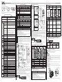
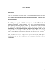
Smart HCFA,creative future!
HCA5 User’s Manual
Major features for HCA5 Programmable Controller
Safety Precautions
(Read these precautions before use.)
Before installation, operation, maintenance or inspection of this product, thoroughly read
through and understand this manual and all of the associated manuals. Also, take care to
handle the module properly and safely.
CAUTION
This manual classifies the safety precautions into two categories: DANGER and
Indicates that incorrect handling may cause hazardous conditions,
resulting in death or severe injury.
CAUTION
Indicates that incorrect handling may cause hazardous conditions,
resulting in medium or slight personal injury or physical damage.
CAUTION may also cause
Depending on the circumstances, procedures indicated by
severe injury.
It is important to follow all precautions for personal safety.
Store this manual in a safe place so that it can be taken out and read whenever necessary.
Always forward it to the end user.
1. DESIGN PRECAUTIONS
DANGER
Make sure to have the following safety circuits outside of the PLC to ensure safe system
operation even during external power supply problems or PLC failure.
Otherwise, malfunctions may cause serious accidents.
(1) Most importantly, have the following: an emergency stop circuit, a protection circuit,
an interlock circuit for opposite movements (such as normal vs. reverse rotation), and
an interlock circuit (to prevent damage to the equipment at the upper and lower
positioning limits)
(2) Note that when the PLC CPU detects an error, such as a watchdog timer error, during
self-diagnosis, all outputs are turned off. Also, when an error that cannot be detected
by the PLC CPU occurs in an input/output control block, output control may be disabled.
External circuits and mechanisms should be designed to ensure safe machinery
operation in such a case.
(3) Note that the output current of the 24V DC service power supply varies depending on
the model and the absence/presence of extension blocks. If an overload occurs, the
voltage automatically drops, inputs in the PLC are disabled, and all outputs are turned
off.External circuits and mechanisms should be designed to ensure safe machinery
operation in such a case.
(4) Note that when an error occurs in a relay, triac or transistor output device, the output
could be held either on or off.For output signals that may lead to serious accidents,
external circuits and mechanisms should be designed to ensure safe machinery
operation in such a case.
Main Unit
DANGER
[Programmable controller]
Programmable controller of HC series is composed of power supply, CPU, memory
cassette and input/output. 24V DC power supply is built in PLC of AC power and DC
input type , worked as the sensor or the like power supply.
[Removable terminal blocks]
Removable terminal blocks are built in basic unit and extension units with good
maintenance performance.
[Built-in RUN/STOP switch]
The PLC can be started and stopped with the built-in switch, which is under the top cover.
[Program memory]
The PLC has an 8K-step RAM memory.
Use of the memory cassette enables the program memory to be 16K-step.
Optional memory cassette: RAM, EEPROM, EPROM
[Built-in clock function]
The PLC has a clock function to control the time.
[Writing during RUN]
The programming software for personal computer and A7PHP/ A7HGP enables you to
modify the program while the PLC is running.
[Comments]
Comments can be created in the program memory by parameter setting. And character
comments and display of programming can be realized in peripheral devices of characters
input.
[Keywords protection program]
Program memory is set as three-level protection to avoid the misinput and stolen of
sequence control.
2. Selecting methods
4. Number of special extension and 5V power supply capacity
When building system with HCA5 series, make sure to consider the following.
①The total number of input/output points (Including occupied points of special blocks) must
be 256 points or less on the whole system.
②Power capacity
Basic units and extension units are built-in power supply, providing 24V DC to extension
blocks and 5V DC to special blocks.
The current consumption of extension blocks and special blocks is not more than the capacity
of the main unit built-in power supply.
③Max special units and special blocks connected to HCA5 main unit is 8.
Make sure to consider the number of extension and DC5V current consumption when using
special units, special blocks and expansion boards.
①Number of Input/ output points
Input/ output points to PLC are shown below.
Input points: 184 or less
Output points: 184 or less
Total numbers: 256 or less
The number of input/output points of special units and special blocks are excluded
from total number of I/O points of PLC.
256 (Max. number of I/O points)-8(Number of special units/ blocks occupied points
*1 ) *Number of units= I/O points controllable on system *1 The occupied points of
HCA5-16CCL-M, HCA5-64CL-M, HCA5-16LNK-M, HCA5-ASI-M may exceed 8.
Expansion boards and special adapters do not occupy I/O points.
Basic Unit
Models
Special function
expansion board
Special units
Max.1
Connected to the upper part of panel of basic units
Max.8
Some devices of the following are restricted in the
number of connecting units
Special blocks
HCA5
Items
HCA5
Basic unit
Combination
<Only extension units connected>. Do not calculate the power capacity.
Basic unit + Extension
And confirm the number of I/O points
units…..Extension units
in Subsection ①.
I/O Extension
Basic unit + Extension
blocks…..Extension blocks
And confirm the number of I/O points
<Only extension units connected>. in Subsection①and calculating power
Basic units, other extension device capacity of 24V DC according to 1-3-3
+Extension units+ Extension
blocks+….Extension blocks
And confirm the number of I/O points
Special Device W h e n c o n n e c t i n g s p e c i a l u n i t s , in Subsection ①and calculating power
special
blocks,
function
expansion
capacity of 5V DC according to this
Extension
boards to the above combination. manual.
HCA5
HCA5
HCA5
Power supply range
Power supply capacity calculation of 24V DC & 5V DC is shown below.
③Number of special function
CAUTION
HCA5
HCA5
DC5V power supply can be provided to special blocks and expansion boards in the following
range.
DC5V power supply
DC5V power supply
Special
HCA5
Extension units
Special
Special Special
Special function expansion board
B: Extension blocks
Special B: Special blocks Special U: Special units
Basic unit and extension units provide DC5V to the next special block. Special units have
built-in power.DC5V power supply can be created by extension cables. There's no need for
external wiring.Special function expansion boards are powered-on by basic units and don't
need any wiring.
DC5V capacity calculating
DC5V power supply of each unit is shown below.
For details of current consumption of special blocks, please refer to Section 1-2.
<DC5V power capacity>
Power capacity
Models
HCA5 Basic unit
2. INSTALLATION PRECAUTIONS
Remarks
②Power capacity
1. Part names
Extension units,
Special units
Extension blocks,
Special blocks
The maximum units to the basic units are shown below.
Number of
connecting units
)
Names and Functions of Parts
The programmable controller is built-in power supply+ CPU+ Input/ output+ Program
memory(RAM). The main processing unit of PLC is also called as Basic unit. Extension units
and blocks are available to extend the Input/ output points. And extension units(power
supply+ input/ output) and extension blocks(input/ output) are available. Moreover, special
function extension devices can be used to have the special control.
Number of Connecting Units
HCA5 Basic unit
Remarks
DC5V current of CU, memory cassette, connectable
evices on programming port are excluded.
Special function expansion boards cannot be connected
For details, please refer to this manual for the connecting of special units and special blocks.
Special blocks
3. Extension points and DC24V power supply capacity
Use the product within the generic environment specifications described in section 1-4
of this manual.Never use the product in areas with excessive dust, oily smoke, conductive
dusts, corrosivegas (salt air, Cl2, H2S, SO2or NO2), flammable gas, vibration or impacts,
or expose it to high temperature, condensation, or rain and wind.If the product is used
in such conditions, electric shock, fire, malfunctions, deterioration or damage may occur.
When drilling screw holes or wiring, make sure cutting or wire debris does not enter the
ventilation slits.Failure to do so may cause fire, equipment failures or malfunctions.
Be sure to remove the dust proof sheet from the PLC's ventilation port when installation
work is completed.Failure to do so may cause fire, equipment failures or malfunctions.
Connect the extension cables, peripheral device cables, input/output cables, battery
connecting cables and memory cassette securely to their designated connectors.
Loose connections may cause malfunctions.
Basic unit and extension units can provide DC24V power supply for extension blocks.
Check whether the I/O points of extension equipment to be connected is not more than the
capacity of the main unit built-in power supply. Below is the example.
TX2N-8EX
HCA5-8X8YR
DC24V Power supply
3. WIRING PRECAUTIONS
Basic unit
DANGER
Make sure to cut off all phases of the power supply externally before attempting installation
or wiring work.Failure to do so may cause electric shock or damage to the product。
Make sure to attach the terminal cover, offered as an accessory, before turning on the power
or initiating operation after installation or wiring work.
Failure to do so may cause electric shock
Special
DESIGN PRECAUTION
B: Extension blocks
Special B: Special function blocks, special units
Basic unit and extension units provide DC24V to the extension block. It needs wiring externally
when extension blocks are used for input.
CAUTION
DC 24V capacity calculating
Magnified
The capacity of DC24V varies depending on the models.
24V DC service power supply is not provided in DC power and AC input products.
Magnified
Models
DANGER
CAUTION
Turn off the power to the PLC before attaching or detaching the memory cassette. If the
memory cassette is attached or detached while the PLC's power is on, the data in the
memory may be destroyed, or the memory cassette may be damaged.
Do not disassemble or modify the PLC.
Doing so may cause fire, equipment failures, or malfunctions.
For repair, contact HCFA Corporation limited.
Turn off the power to the PLC before connecting or disconnecting any extension cable.
Failure to do so may cause equipment failures or malfunctions.
5. DISPOSAL PRECAUTIONS
CAUTION
Please contact a certified electronic waste disposal company for the environmentally
safe recycling and disposal of your device.
1
Power capacity
HCA5-16M、32M、32E
250mA
HCA5-48M~128M HCA5-48E
4 60mA
Remarks
Power supplied to
extension blocks
The current consumption varies depending on the input/ output of extension blocks.
When special function units/blocks are connected, it is necessary to consider whether they can
be covered by this remaining power supply capacity.
This remaining power supply capacity (current) can be used as a power supply to external
loads (sensors or the like) by the user.
4. STARTUP AND MAINTENANCE PRECAUTIONS
Do not touch any terminal while the PLC's power is on.
Doing so may cause electric shock or malfunctions.
●Before cleaning or retightening terminals, cut off all phases of the power supply externally.
Failure to do so may cause electric shock.
●Make sure to connect the battery for memory backup correctly.
Do not charge, disassemble, heat, short-circuit, or expose the battery to fire.
Doing so may rupture or ignite it.
●Before modifying or disrupting the program in operation or running the PLC, carefully
read through this manual and the associated manuals and ensure the safety of the operation.
An operation error may damage the machinery or cause accidents.
( If the calculation results for the current
consumption for the 5V DC power supply
are negative values, add an input/output
powered extension unit.)
5. Generic specification
Special HCA5
Extension
unit
HCA5
Connect the AC power supply to the dedicated terminals specified in this manual.If an
AC power supply is connected to a DC input/output terminal or DC power supply terminal,
the PLC will burn out.
Do not supply power to the [24+] and [24V] terminals (24V DC service power supply) on
the main unit or extension units.Doing so may cause damage to the product.
●DO NOT use the “● ”vacant terminals in PLC.
●Perform class D grounding (grounding resistance: 100 Ωor less) to the grounding terminal
on the main unit and extension units with a wire 2 mm2 or thicker.
Do not use common grounding with heavy electrical systems。
basic
Current
consumption
(Refer to
)
The max. number of extension units for HCA5-16M, HCA5-32M are two; and max. number
of extension units for HCA5-48M~128M are three. If connecting more TX0N-3A, add extens
ion units (HCA5-32E, HCA5-48E).
Connecting example: HCA5-48MR, HCA5-3A*3
290 mA -(30*3) mA -70mA(Built-in power)=130mA≥0 (Connectable)
Power supply range
DC24V Power supply
capacity
Total
capacity of
power supply
Magnified
⑴ 35mm DIN rail
⑵ 4 Mounting holes (φ4.5)
Two mounting holes for 32 points or less
⑶ Input terminals and power supply terminals
(Excluding 16 points PLC)
⑷ Input LED Status Indicators
⑸ Extension units, extension blocks, special
units, special blocks, connecting connectors
and connector cover
⑹ Output terminals (Excluding TX2N-16M)
⑺ Output LED Status Indicators
⑻ DIN Rail Mounting Clip
⑼ Top cover
⑽ Peripheral device connecting connector and
cover
Magnified
or
⑾ PLC Status Indicators
POWER: On while power to the PLC is on.
RUN: On while the PLC is running.
BATT.V: Lights when the battery voltage
drops.
PROG-E: Flashing when a program error
occurs.
CPU-E: Lights when a CPU error occurs.
⑿ Lithium Battery (F2-40BL, Standard
accessory)
⒀ Battery connector
⒁ Memory cassette connector
⒂ Expansion board connector
⒃ RUN/STOP switch
⒄ Programming and GOT connector
⒅ Model name
2
Input
Extension
blocks
( points
)
Number or
Extension
blocks
Output
Extension
blocks
( points
)
7
DANGER
Make sure to have the following safety circuits outside of the PLC to ensure safe system
operation even during external power supply problems or PLC failure.
Otherwise, malfunctions may cause serious accidents.
1) Most importantly, have the following: an emergency stop circuit, a protection circuit, an
interlock circuit for opposite movements (such as normal vs. reverse rotation), and an
interlock circuit (to prevent damage to the equipment at the upper and lower positioning
limits).
2) Note that when the PLC CPU detects an error, such as a watchdog timer error, during
self-diagnosis, all outputs are turned off. Also, when an error that cannot be detected
by the PLC CPU occurs in an input/output control block, output control may be disabled.
E x te r n a l c i r c u i ts a n d m e c h a n i s m s s h o u l d b e d e s i g n e d to e n s u r e s a fe m a c h i n e r y
operation in such a case.
3) Note that the output current of the 24V DC service power supply varies depending on
the model and the absence/presence of extension blocks. If an overload occurs, the
voltage automatically drops, inputs in the PLC are disabled, and all outputs are turned off.
E xte r n a l c i rc u i ts a n d me c h a n i s ms s h o u l d b e d e s i g n e d to e n s u re sa fe ma ch i n e ry
operation in such a case.
4) Note that when an error occurs in a relay, triac or transistor output device, the output
could be held either on or off.
For output signals that may lead to serious accidents, external circuits and mechanisms
should be designed to ensure safe machinery operation in such a case.
Environment Specification
Ambient temperature 0 to 55°C when operating and -25 to 70°C when stored
Number or
Extension
blocks
Ambient humidity
( This remaining power supply capacity (current) can be used as a power supply to external
loads (sensors or the like) by the user. When special function units/blocks are connected,
it is necessary to consider whether they can be covered by this remaining power supply
capacity. If the calculation results for the current consumption for the 24V DC power supply
are negative values, add an input/output powered extension unit.
※When using extension blocks of 16 points, the number of extension blocks should be two.
When using input/output extension blocks, the number of extension blocks(HCA5-8ER) should
be 0.5 respectively.
[Connecting example]
HCA5-48MR, HCA5-8EX, HCA5-16EX, HCA5-8EYR
460 mA -50 mA*1-50 mA*2-75 mA=235 mA≥0 (Can be extended)
Frequency Acceleration Half amplitude
( Hz )
( m/s2 )
(mm)
Sweep
Count for
0.035
When installed 10 to 57
X, Y, Z:
Vibration resistance on DIN rail
4.9
57 to 150
10 times
(80 min in
0.035
When installed 10 to 57
each
directly
57 to 150
direction)
9.8
Shock resistance
Noise resistance
3
147 m/s2 Acceleration, Action time: 11ms, 3 times by half-sine pulse
in each direction X, Y, and Z
By noise simulator at noise voltage of 1,000 Vp-p, noise width of 1
µs, rise time of 1 ns and period of 30 to 100 Hz
Dielectric
withstand voltage
1.5kV AC for one minute ※1
Between each terminals*2
and ground terminal
Insulation resistance 5MΩor more by 500V DC megger
Class D grounding (grounding resistance: 100 Ωor less) ※2
Grounding
<Common grounding with a heavy electrical system is not allowed>
Working atmosphere
Remaining capacity of DC24V
35~85%RH (no condensation) when operating
Free from corrosive or flammable gas and excessive conductive
dust Working
4
Smart HCFA,creative future!
HCA5 User’s Manual
Power specification
※1: Based on I EC61131-2
※2: DC power type: AC500V
※3 : Ground the PLC independently or jointly.
PLC
Another
equipment
Independent grounding
Best condition
PLC
Another
equipment
PLC
Shared grounding
Good condition
Another
equipment
Common grounding
Not allowed
※4 : Do not use the PLC under pressure higher than the atmospheric pressure. Doing so
may damage the PLC.
HCA5 Series
Circuit
Protection Fuse
25W
30W
35W
24V + supply power to [24+]
<Extension Blocks>
terminal o f input extension block s
DC Input
External
power supply
1.AC Power Supply, DC Input Type
Connet power supply to the L$N terminal
(In any case of 100Vac \ 200Vac system)
Connection
diagram
-
1. Input specification
Class D Grounding
Models
Note):
DC Input
<AC power type>
Basic unit
HCA5 Extension unit
DC Input
DC Input
<DC power type>
HCA5 Basic unit
HCA5 Extension unit
T246 to T249, 4 points, 0.001 to 32.767 sec
FUSE
Input signal
voltage
Input signal
current
C200 to C219, 20 points, Counting from -2,147,483,648
to +2,147,483,647
C220 to C234, 15 points, Counting from -2,147,483,648
to +2,147,483,647.
<Extension Blocks>
AC Power Supply /
DC Input
Note):
Service
Power Supply
Emergency Stop, refer to
[Design precautions]
[24+] Terminal on the basic unit
and extension units cannot be
connected with each other
Up to 6 points can be used in range from C235 to C255.
D0 to D199, 200 points
D200 to D511, 312 points
D512 to D7999, 7488 points
D8000 to D8511, 106 points
V0 to V7, Z0 to Z7, 16 points
Power supply for loads to be
connected to PLC output terminals
Note):
Note):
<Extension Blocks> [24+] Terminal on extension
units supply power to [24+]
DC Input
terminal on input extension block
I0□□to I8□ □, 9 points
I010 to I060, 6 points
N0 to N7, 8 points
Decimal number (K) 16 bits: -32,768 to +32,767
32 bits: -2,147,483,648 to +2,147,483,647
Hexadecimal number 16 bits: 0 to FFFF
(H)
32 bits: 0 to FFFFFFFF
<Changing allowable instantaneous power failure time>
※1: Non-battery retentive status. The retentive status can be changed by parameter settings.
※2: Battery retentive status. The retentive status can be changed by parameter settings.
※3: Fixed retentive status. The status characteristics are unchangeable.
5
0-step
30W
②1.5W/ DC24V
③1W/ DC24V
④3W/ DC24V
1mA/AV100V, 2mA/AC200V
0.1 mA /DC30V
Open circuit
leakage current
Min. load
DC 5V 2mA reference value 0.4VA/AC100V, 1.6VA/AC200V)
OFF→ON About 10 ms
1ms or less
0.2ms or less(Y000,Y001: 15ms)
OFF→ON About 10 ms
10ms or less
0.2ms or less(Y000,Y001: 30ms)
Maintenance and Periodic Inspection
This PLC does not incorporate consumable parts that are factors in the reduction of service life.
However, the batteries have a limited life expectancy.
Periodic
inspection
Battery life and
regular replacement
Program
memory type
24V DC ±10%*2
7mA/24V DC(5 mA/24V DC in X010 and more) 5 mA/24V DC
4.5mA or more(3.5 mA or more/24V DC in 3.5 mA or more
X010 and more)
1.5mA or less
1.5mA or less
About 10 ms
About 10 ms
Input
response
Built-in Digital filter in X000~X017. *3
time
Can be change from 0~60 ms. *4
Input signal Contact input or NPN open collector transistor
Input circuit Insulation with photocoupler
insulation
100~120V AC-15%, +10%
6.2mA/110V AC 60Hz*5
Battery service life and replacement period
Approx.
Standard life
Regular replacement
expectancy
minimum lifetime
time
1 year
5 year
3 year
Input ON current
3.8mA or more
Input OFF current
1.7 mA or less
About 25~30 ms
High-speed input is not
allowed.
Contact input
Insulation with photocoupler
LED on panel is lit when
there is input.
Before replacing the battery
Step 4 of the replacement procedure (below), must be performed within 20 seconds after step
3, or the memory content could be lost.
1 Turn the power OFF.
2 Remove the battery cover.
Slightly lift the right side of the battery cover. Grasp the cover between your fingers and
remove it.
3 Remove the old battery.
Extract the old battery from the battery holder, and disconnect the battery connector.
4 Install the new battery.
Connect the battery connector to the new battery, and insert the battery into the battery holder
within 20 seconds.
5 Attach the battery cover
F 2 -40BL type Battery
*1: Input impedance is 4.3 kΩ in X010 and more of extension units.
*2: The DC power type applies to the power supply voltage range of each unit.
*3: 16M: X000 to X007.
*4: X000,X001: MIN.20ms; X002: MIN.50ms
*5: 70% or less when turned on simultaneously.
CAUTION
WIRING PRECAUTION
the AC power supply to the dedicated terminals specified in this manual.
If an AC power supply is connected to a DC input/output terminal or DC power supply
terminal, the PLC will burn out.
●Do not supply power to the [24+] and [24V] terminals (24V DC service power supply) on
the main unit or extension units.
Doing so may cause damage to the product.
●DO NOT use the “ ● ”vacant terminals in PLC.
●P e r f o r m c l a s s D g r o u n d i n g ( g r o u n d i n g r e s i s t a n c e : 1 0 0 Ω o r l e s s ) t o t h e g r o u n d i n g
terminal on the main unit and extension units with a wire 2 mm2 or thicker.
Do not use common grounding with heavy electrical systems。
Battery
●Connect
When the supply voltage of PLC is 200V AC, the time can be change to 10 to 100 ms by
editing the user program to change the contents of D8008 in special data register.
20ms ( Intital value of D8008:10ms)
Input first before
programming
24V DC ±10%*2
Indication of
input operation LED on panel is lit when there is input.
Vacant terminal. Do not wire vacant
terminal externally. Don' t use It As
connection terminals.
※1: The same power source for the main unit, extension unit and special function unit/block
is preferable. When using the different power source from the main unit, turn ON the
peripheral devices' power simultaneously, or earlier than the main unit's. When turning
OFF the power, confirm the safety of the system and then turn OFF the power of the PLC
(including special extension equipment) at the same time.
P0~P127, 128 points
100W
When the battery voltage is low, a "BATT" LED lights (red) while the power is ON, and M8005
and M8006 are switches ON.
Although the battery will continue to function for approximately 1 month after the "BATT" LED
switches ON, a replacement battery should be ordered and installed as soon as possible.
Convertor
C100 to C199, 100 points, Counting from 0 to 32,767.
light load
7.2W/ DC24V)
②12W/DC24V
③7.2W/ DC24V
④24 W/ DC24V
Battery
replacement
T250 to T255, 6 points, 0.1 to 3,276.7 sec
C0 to C99, 100 points, Counting from 0 to 32,767.
15VA/ AC 100V
30VA/ AC 200V
care that output relay working with high frequency and driving large capacity load may
lead to considerable reduction of the product life.
●When inspecting the battery, check the following points.
Check that the temperature in the panel is not abnormally increased by other heat generating
bodies or direct sunlight.
Check that dust or conductive dust has not entered the panel.
Check for loosening of wiring and other abnormalities.
Input circuit
Extension Cable
80VA
(Refer to life
expectancy in 6-2)
●Take
Breaker
[24+] Terminal on extension
<Extension Blocks> units supply power to [24+]
DC Input
terminal on input extension block
①12W/DC 24V(Y000,Y001:
Inductive
load
Built-in memory
EEPROM memory
cassette
EPROM memory
cassette
DC Input
service
power
supply
DC24V
Service
Power Supply
1.6A/ 8points
0.9W/DC24V)
20ms ( Intital value of D8008: 10ms)
Initial pulse
1.6A/ 8points (Y000.Y001:
0.3A/ point)
②0.5 A/ 1 point, 0.8A/ 4 points,
①1.5W/ DC24V(Y000,Y001:
main sequence program follows.
D8008 is a kind of data register used for setting the time of power failure detection . It turns
out to be 5ms after written into K-1.
Items
Convertor
Emergency Stop, refer to
[Design precautions]
Note):
Vacant terminal. Do not wire
vacant terminal externally.
Don' t use It As connection
terminals. Don' t wire 24V
terminal externally. External
device malfunction and short
circuitmay burn out fuse of PLC
Input/ output specification
For details, please refer to
[Wiring Precautions]
FUSE
5~30V DC
③0.3A/ 1 point, 1.6A/ 16points
④1A/1 point, 2A/ 4 points
As to DC24V, the current consumption of input extension blocks [24+] terminal is
<5mA(Input current)+Input points>.
※1: The same power source for the main unit, extension unit and special function unit/block
is preferable. When using the different power source from the main unit, turn ON the peripheral
devices' power simultaneously, or earlier than the main unit's. When turning OFF the power,
confirm the safety of the system and then turn OFF the power of the PLC (including special
extension equipment) at the same time.
<Correction of allowable instantaneous power failure time>
Operation of PLC can be continued upon occurrence of instantaneous power failure for 5
ms or less. In order to correct the instantaneous power failure time, K-1 should be written
into D8008(9-1) of data register..
Input first before
programming
0.3A/ 1 point
0.8A/ 4 points COM
0.8A/ 8 points COM
Power supply for loads to be
connected to PLC output terminals
Note):
0-step
85~242V AC
photo-thyristor insulation Photocoupler insulation
2A/ 1 point
8A/ 4 points COM
8A/ 8 points COM
Note):
Response
time
☆Power supply of basic units and extension units should be turned ON/OFF
simultaneously.
☆To avoid the voltage drop of power cable, All power cables must be at least 2mm2.
☆Operation can be continued upon occurrence of instantaneous power failure for 10
ms or less. Long-time power failure and abnormal voltage drop will make the PLC
stop and all outputs are turned off.
☆Use a cable at least 2mm2(AWG14) to ground equipment. Ground resistance must
be less than 100 Ω. Note that the ground cable must not be connected to the same
ground as the power circuits.
External
power supply
External
power supply
External
30V DC or less or 250V
power supply AC or less
Circuit insulation Mechanical insulation
Resistance
load
●Connect
<Basic Unit>
AC Power Supply /
DC Input
M1024 to M3071, 2048 points
M8000 to M8255, 256 points
S0 to S9, 10 points
S10 to S499, 490 points
S500 to S899, 400 points
S900 to S999, 100 points
T0 to T199, 200 points, 0.1 to 3,276.7 sec
T200 to T245, 46 points, 0.01 to 327.67 sec
Output
circuit
Convertor
<Extension Blocks>
AC Power Supply /
DC Input
<Extension Blocks> 24V + supply power to [24+]
terminal o f input extension block s
DC Input
the AC power supply to the dedicated terminals specified in this manual.
If an AC power supply is connected to a DC input/output terminal or DC power supply
terminal, the PLC will burn out.
●Do not supply power to the [24+] and [24V] terminals (24V DC service power supply) on
the main unit or extension units.
Doing so may cause damage to the product.
●DO NOT use the“ ●”vacant terminals in PLC.
●Perform class D grounding (grounding resistance: 100 Ωor less) to the grounding terminal
on the main unit and extension units with a wire 2 mm2 or thicker.
Do not use common grounding with heavy electrical systems。
Load
Load
Display of
LED on panel lights when LED on panel lights when LED on panel lights when
output operation power is applied to relay coil. photo-thyristor is driven. photocoupler is driven
①0.5A/ 1 point, 0.8A/ 4 points,
40W
CAUTION
WIRING PRECAUTION
Transistor output
①HCA5 basic unit, extension unit
②HCA5 Extension blocks
③HCA5-16EYT-C
④HCA5-8EYT-H
Extension Cable
Note):
M0 to M499, 500 points
M500 to M1023, 524 points
Load
Note):
Power fuse
Power consumption
Service power supply --
Models
Large current
blocks
Emergency stop
Constant
Refer to Input/ output specification.
Supply voltage
Allowable supply
-30%~+20%
voltage range
Allowable instantaneous Operation can be continued upon occurrence of instantaneous power
failure for 5 ms or less.
power failure time
Triac Output
HCA5 Basic unit
Extension unit
Extension blocks
Note):
HCA5-80M□-D
Power on
Input/output relay
For general
[changeable] ※1
For keeping
Auxiliary
[changeable] ※2
relay
For keeping [fixed] ※3
For special
Initial state
For general ※1
State
For keeping ※2
For annunciator ※2
100 ms
10ms
Timer
1ms accumulating
(on-delay
t y p e ※3
timer)
100ms accumulating
type ※3
Increment for general
(16 bits) ※1
Increment for keeping
(16 bits) ※2
Both directions for
Counter
general (32 bits) ※1
Both directions for
general (32 bits) ※2
High-speed in both
direction (32 bits) ※2
For general (16 bits) ※1
Data
For keeping (16 bits) ※2
register
(32 bits
For keeping (16 bits) ※3
when
For special (16 bits)
paired)
For index (16 bits)
For branching of
JAMP and CALL
Input interruption and
Pointer
timer interruption
Counter interruption
Nesting
For master control
HCA5-32M□-D HCA5-48M□-D HCA5-64M□-D
HCA5-48E□-D
24V DC
Items
Relay output
HCA5 Basic unit
Extension unit
Extension blocks
Class D
Grounding
<Basic Unit>
AC Power Supply /
DC Input
DC Power Supply Type, DC Input Type
The attachment
RAM 16000-steps(2k-, 4k-, 8k-step memory can be
selected.)
EPROM 16000-steps(2k-, 4k-, 8k-step memory can be
selected.)
Memory cassette
EEPROM 4000-steps (2k-step memory can be selected.)
(Option)
E E P R O M 8 0 0 0 - s te p s ( 2 k - , 4 k - - s t e p m e m o r y c a n b e
selected.)
EEPROM 16000-steps(2k-, 4k-, 8k-step memory can be
selected.)
Memory cassette with RTC is not allowed.
Writing function during Provided (Program can be modified while the PLC is
running.)
running
Built-in(Memory cassette with RTC is not allowed)
1980 to 2079 (with correction for leap year)
Real-time Clock function
2- or 4-digit year, accuracy within ±45 seconds/month
clock
at 25°C
Sequence instructions: 27; Step-ladder instructions: 2
Basic instructions
Kinds of
instructions Applied instructions 132 kinds, 309 instructions
0.08 µs/instruction
Processing Basic instructions
speed
Applied instructions 1.52 µs to several hundred µs/instruction
Extension-combined
Number of number of input points X000-X267, 184 points (The device numbers are octal.)
input/output Extension-combined
number of output points Y000-Y267, 184 points (The device numbers are octal.)
points
Total number of points 256 points
Program
memory
50 / 60 Hz
Operation can be continued upon occurrence of instantaneous power
Allowable
instantaneous power failure for 10 ms or less.
When the supply voltage is 200V AC, the time can be change to 10 to
failure time
100 ms by editing the user program.
Power fuse
250V, 3.15A(3A)5□*20mm 250V, 5A 5□*20mm
Power consumption
30
40
50
60
70
100
40 A max. 5 ms or less/100V AC, 60 A max. 5 ms or less/200V AC
Rush current
No
extension
Sensor
DC 24V, 250mA or less DC 24V, 460mA or less
power blocks
supply With extension Refer to manual.
blocks
Convertor
Items
Max. load
Stored program repetitive operation system (dedicated
LSI) with interruption function
Batch processing system (when END instruction is
Input/output control system
executed) Input/output refresh instruction and pulse
catch function are provided.
Relay symbol system + step-ladder system (SFC notation
Programming language
possible)
16000-steps
Max. memory capacity Comments and file registers (Max. 16000-steps) can be
created in the program memory by parameter settings.
8000-step RAM (backed up by built-in lithium battery)
Battery life: Approx. 5 years, approx.. 3 years with
Built-in memory
RAM memory cassette( Guaranteed 1 year)
capacity/type
With password protection function (with entry code
function)
Operation control system
85 to 264V AC
Connection
diagram
Emergency stop
Items
HCA5-16M HCA5-32M HCA5-48M HCA5-64M HCA5-80M HCA5-128M
HCA5-32E HCA5-48E
100 to 240V AC
※1 Provide a 3-5A fuse to prevent blowout of wires on the circuit
boardcaused by external deivce malfunction & short circuit.
Power on
Performance Specification
Items
Supply voltage
Allowable supply
voltage range
Rated frequency
2. Output specification
2. DC Power Supply, DC Input Type
AC Power Supply Type, DC Input Type
K20 is written into D8008
Initial pulse
main sequence program follows.
6
7
Battery connector
●Note:
No touch with the battery contact piece when installing function expansion boards.
8