1
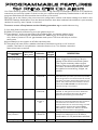
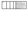
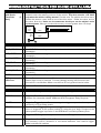
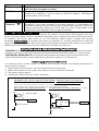
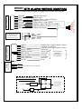
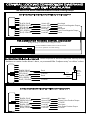
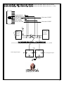
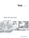
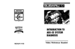
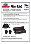
INSTRUCTION MANUAL FOR
Remote Control Car Alarm with Impact Sensor,
Mini-Battery Backup Siren & Engine Immobiliser
SYDNEY / AUSTRALIA
Build Date:
A.C.N 001 621 610
TO ARM/DISARM ALARM
The alarm is activated by pressing BUTTON 1 on the remote control transmitter once.
The blinkers will flash once, and the siren will beep once. The dash LED-light will stay on
for 10 seconds then flash, THE ALARM IS NOW ON.
To deactivate the alarm, press the BUTTON 1 again. The blinkers will flash twice and
the siren will beep twice. THE ALARM IS NOW OFF.
If the siren is sounding, and you wish to disarm, the first press will cancel the siren the system will then return to an armed state. A second press is required to fully turn
the alarm off (you will hear 2 beeps & the blinkers will flash twice) .
1 2
BOOT RELEASE - Available on cars fitted with electric boot release
motors.
The alarm is fitted with remote boot release capability. This feature enables the user to unlock the boot by
pressing BUTTON 2 for 2 seconds. The boot will unlock and the indicators will flash 14 times.
For safety reasons, the remote boot release will not work when the ignition is on.
DOOR AJAR WARNING & BYPASS
When arming, if the alarm senses that a door has been left open, 4 seconds after the normal arming beep,
the siren will beep a further 5 times. The door trigger input will be automatically bypassed to prevent false
alarms.
ALARM TRIGGER & MEMORY
When the alarm is triggered the siren will sound for 30 seconds and then will automatically rearm.
If the alarm has been triggered in your absence, the dash LED will be flashing twice as fast as normal when
you return to your vehicle.
EMERGENCY PANIC BUTTON
The panic feature is activated by pressing & holding BUTTON 1 on the remote control transmitter for 2
seconds. If disarmed, the alarm system will arm first (i.e. lock doors) then the siren will sound & the blinkers
will flash for 30 seconds. If armed, the alarm system will stay armed (i.e. the doors will not unlock) & the
siren will sound & blinkers flash for 30 seconds.
To cancel “panic”, follow disarm procedure as desribed on page 1.
NOTE: Panic does not work when the ignition is on by requirement of Australian Law (EPA-Environmental
Protection Authority).
1
PROGRAMMABLE FEATURES:
The features outlined below are the most popular that can be turned on or off to suit your requirements.
Please refer to the section is this manual marked “Rhino Programmable Features” for full details.
PASSIVE ARMING: The alarm can automatically arm itself 30 seconds after you leave your vehicle
provided that the ignition is turned off, and that at least one door has been opened and closed ie. the owner
has parked and has exited the vehicle. This feature will not lock the vehicle where central locking is
connected.
AUTOMATIC RE-ARM : This feature prevents accidental disarming by the owner ie. the owner turns the
alarm off but is then distracted and forgets that they have deactivated the system. If a door is not opened,
or the ignition is not turned on within 60 seconds from when the system is turned off by the remote, the
system will re-arm, and if central locking is connected, it will re-lock the vehicle.
SILENT ARM/DISARM : This feature when turned on, stops the siren from beeping for arm & disarm
confirmation i.e. only the blinkers will flash.
LEARNING NEW REMOTES (Up to 3 remotes can be used with this alarm system)
Before entering this mode,make sure you have all remotes present that you wish yo utilise with this alarm
system, as the alarm automatically erases all remotes when you enter this mode.
A. Arm then Disarm the alarm system. While the system is disarmed, open and close your drivers door (get
inside the vehicle), making sure the interior light is coming on as you open the door.
B. Within 30 seconds, turn the car ignition key from the off position to the ignition on position 8 times.
C. 10 seconds later, the blinkers will flash 8 times to confirm that you have entered the remote learning
mode. Repeat steps A & B if you do not receive the flashes.
D. Now press & hold Button 1 on the new remote you wish to learn in. The siren will beep once to confirm
the code has been learnt. Repeat this step for up to 3 remotes. You can use this process to delete lost
remote controls by learning in the same remotes in succession to replace each of the 3 memory
locations so that the old remote code/s are erased.
E. The system will automatically exit the learning mode 20 seconds after the last press of a remote.
2
STANDARD SYSTEM FEATURES
2 x Remote Controls
Smart Code Learning Technology
1 Point Engine Immobilisation (Onboard Relay)
Can Protect Doors, Boot, Bonnet
Car Body Impact Sensor
Mini Backup Battery Siren
Flashes Indicators
Flashing Red Dash Light
Central Locking Control for Keyless Entry
Arm/Disarm Beep
Emergency Panic via Remote
Car Finder Function
Current (Voltage Drop) Sensing
Automatic Siren Reset (30 seconds)
Security Override Mode
Boot Release via Remote (where fitted)
Split System - Separate Siren & Brain
SELECTABLE SYSTEM FEATURES
Passive Arming
Auto Rearm & Relock
Audible or Quiet Arm/Disarm
Current Sensing (Voltage Drop) Circuit
Central Locking Output Time Selectable - 0.8 or 5 Seconds
OPTIONAL ACCESSORIES:
Automatic Electric Window Lift
Paging System
Ultrasonic Sensors
Microwave Sensor
(Part No. GLU400 - Closes 2 Windows)
(Part No. APAGER)
(Part No. UD6)
(Part No. UD5)
3
Your Rhino Security system incorporates the latest in high security & convenience features. It is possible to
customise your security system so that it suits your requirements perfectly. Detailed below is the full list of
programmable features that can either be turned on or turned off.
We have set at the factory, the most common configuration chosen and these settings are listed in the
REGISTER Settings listed below. Once the desired features have been selected, the selection is permanently
retained in memory, even if power is removed.
To turn on or turn off any feature use the following procedure: eg to enable silent arming.
1. Arm then disarm the alarm system.
2. Within 20 seconds of disarming, turn the ignition key to on.
3. Press button 1 on the remote control (immediately after turning the ignition on) an
equal number of times to the selected feature’s code no. (eg 10 times for Audible
arm/disarm). Leave a 0.5 sec. gap between each press. The siren will chirp to confirm
each press.
4. Immediately turn the ignition to off after the last press.
5. The system will now confirm whether the feature has been turned on or off via visual
readout. One flash of the indicators means the feature is on. Two flashes means the
feature has been turned off.
PROGRAMMABLE
FEATURE
Press
Remote This
Many Times
Indication
INITIAL
FACTORY
SETTING
DESCRIPTION
Voltage Drop
(Current) Sensing
6
1 Flash On
2 Flash Off
OFF
If deactivated, this feature will prevent the
alarm triggering via sensing a drop in
voltage in the vehicle’s electrical system.
This may be necessary where engine
thermo fans cut in automatically or there
are other accessories active even when
the ignition is turned off eg fridges, car
phones.
Passive Arming
7
1 Flash On
2 Flash Off
OFF
The alarm can automatically arm itself 30
seconds after you leave your vehicle provided
that the ignition is turned off, and that at least
one door has been opened and closed ie. the
owner has parked and has exited the vehicle.
This feature will not lock the vehicle where
central locking is connected.
Auto Re-arm
8
1 Flash On
2 Flash Off
OFF
If system is disarmed and a door is not
opened, or the ignition turned on within 60
seconds, the system will rearm & relock
(where central locking is connected).
Central Closure
9
1 Flash 0.8
2 Flash 5
sec
0.8 sec
You can select the lock & unlock outputs to
become a 5 second negative pulse instead of
0.8 seconds. This feature is for certain
vehicles with vacuum central locking or those
with a central closure wire (some BMW,
Mercedes) ie doors lock, electric windows
wind up, sunroof closes automatically.
Audible
Arm/Disarm
10
1 Flash On
2 Flash Off
ON
This feature when turned off, stops the
siren from beeping for arm & disarm
confirmation i.e. only the blinkers will flash.
Arming Delay
12
1 Flash On
15 – 45
You can increase the arming delay period
4
Adjustment &
Door Ajar
Warning
2 Flash Off
Sec
from the intital factory setting of 15
seconds up to 45 seconds.
Door Ajar Warning: When the arming
delay is set on 15 sec, if a car door is
left open, when arming the siren will
emit an error chirp after the normal
arming beep. The alarm will also isolate
the door trigger input to prevent trigger
in case of faulty door pin switch.
If arming delay is extended from 15 sec,
this feature will not work. This may be
necessary in vehicles that have an
interior light delay.
5
WIRING INSTRUCTIONS FOR RHINO GTR ALARM
LIGHT BLUE x 2
with Spade
Terminals.
(1
Pair)
-
2 X SPADE CONNECTORS, LEFT HAND SIDE OF MODULE
Immobilisation Circuit. (Starter Motor or Fuel Pump). The starter wire is usually
located under the steering column of the vehicle. This wire must be +12 Volts
only when the vehicle is being started. Cut this wire. The vehicle should not start.
Solder the starter motor side to one of the blue wires. Solder the other end to
the other blue wire. Under no circumstances should you cut the vehicle’s main
ignition system. Wire you cut should not carry current greater than 15 Amps.
Fuel
Pump or
Starter
Motor
BLACK
-
BLUE/YELLOW
-
RED/GREEN
-
BLACK/GREEN
-
RED/BLUE
-
GREEN/YELLOW
-
BLACK/BLUE
-
GREEN
-
RED
15A Fuse
GREEN
with
Main Module
Blue
Blue
LARGE CONNECTOR BLOCK – WIRES LEFT TO RIGHT
Earth. Connect to a suitable earth on the car body.
Lock NO. Refer to diagrams contained later in this manual for central locking
connection .
Lock COM. Refer to diagrams contained later in this manual for central locking
connection .
Lock NC. Refer to diagrams contained later in this manual for central locking
connection .
Unlock NO. Refer to diagrams contained later in this manual for central locking
connection .
Unlock COM. Refer to diagrams contained later in this manual for central locking
connection .
Unlock NC. Refer to diagrams contained later in this manual for central locking
connection .
Indicator Flash Wire. Connect to the left hand indicator circuit of the vehicle.
-
Power. Connect to constant +12 volts via the fuse box at the point where the
interior light circuit is powered. Current (voltage) sensing will not work if this
procedure is not followed. Make sure the fuse is firmly pushed into its holder.
-
Indicator Flash Wire. Connect to the right hand indicator circuit of the vehicle.
SMALL CONNECTOR BLOCK – WIRES LEFT TO RIGHT
Positive LED Output - already connected to the LED supplied.
RED
BROWN
-
Negative Boot Release Output (200mA Max). Please refer to the illustrated
diagram for connection details. Additional 40A Changeover Relay Required.
WHITE
-
YELLOW
-
Negative Trigger Input. Connect to negative trigger output wire from optional
ultrasonics or microwave sensor.
Positive Siren Trigger (1Amp max rating). This wires switches positive when the
alarm is triggered. It also pulses positive to make the siren beep. Connect to the
yellow positive trigger input wire on the SBB Multi-Tone Backup Battery Siren.
BLUE
-
Negative LED Output - already connected to the LED supplied.
PINK
-
Negative on Arm (500mA Max). Connect to the negative wire (usually black) on
any accessory used ie. ultrasonic or microwave detectors. Also used to trigger
electric window lift modules.
6
-
GREY
Ignition Input. Connect to a +12 volts ignition switched lead, which does not fall
to 0 volt when the engine is cranked
-
ORANGE
Connect to existing door switches. Please note: only negative switching doors, if
positive door switching - must use relays to reverse to negative - see diagram
contained later in this manual)
ROUND YELLOW TRIM POT ON FAR RIGHT OF MODULE
YELLOW
Sensitivity Adjustment for Car Body Impact Sensor – using a small philips head
screwdriver, turn gently clockwise to increase sensitivity, or anti-clockwise to
“TRIM POT”
decrease sensitivity. Do not force past stops, otherwise you will break . (This is not
covered by warranty). Adjust trim pot & then arm alarm to test. Make small
adjustments until sensitivity is set to an appropriate level.
CURRENT (VOLTAGE DROP) SENSING
The alarm is fitted standard with current sensing. This feature incorporated in Rhino systems has been
proven to be very reliable. The alarm will detect any sudden drop in voltage in the vehicle’s electrical system,
for example if the interior light comes on, or if the electrical system shows a voltage drop through
tampering. PLEASE NOTE: If removal of this feature is necessary i.e. if engine cooling fans run after the
ignition key is turned off, please refer to the Programmable Features section of this manual. You are able to
disable the current sensing feature so that a false alarm condition can not occur.
LOCATION GUIDE FOR SYSTEM COMPONENTS
THE SIREN: Mount the siren to the vehicle’s firewall, close to the bonnet. DO NOT mount near the exhaust
manifold or low down in the engine bay where it may be exposed to excessive moisture / road grime etc.
THE CONTROL (MAIN) UNIT: Mount under the dash between the steering column & the centre of the
vehicle. Cable tie the unit to a large cable (20mm diameter or larger) or to a heavy strut.
SECURITY OVERRIDE MODE:
If a customer loses a remote control, or it fails to disarm the alarm system, the following procedure will
disarm the alarm system.
1. Open & close the drivers door - sit in the vehicle. (The siren will sound).
2. Within 20 seconds, turn the ignition from off to on 10 times. Wait for 5 seconds.
3. The system will then disarm.
4. Contact your Rhino Dealer for further assistance.
I M P O R T A N T N O T E F O R I N S T A L L E R S : V e h ic le s fitte d w ith n e g a tiv e
o r p o s itiv e s w itc h in g d o o r s .
In o rd e r fo r th e a la rm s ys te m to fu n c tio n c o rre c tly, it is n e c e s s a ry fo r th e d o o rs to b e
h a rd w ire d to th e s ys te m . P le a s e fo llo w th e w irin g d ia g ra m s b e lo w :
P O S I T I V E S W I T C H I N G D O O R S : U s e re la y.
N E G A T IV E S W IT C H IN G D O O R S :
+12V
I n te r io r lig h t
o r a n g e w ir e
ALARM
30
D o o r S w itc h
86
87a
85
8 7 O r a n g e w ir e A L A R M
D o o r S w itc h
+12V
7
RHINO GTR ALARM WIRING DIAGRAM
REFER TO WIRING INSTRUCTIONS ON PAGES 5 & 6 FOR FULL EXPLANATION
SMALL CONNECTOR
ORANGE
GREY
PINK
BLUE
YELLOW
WHITE
BROWN
RED
Mini Backup Battery Siren
USA Pat Des 391,512
Taiwan Pat 85309178
China Pat ZL 98207345.3
RED
+12 VDC
BLACK EARTH
YELLOW
GREEN Not used
BLUE
Not used
GREEN
RED
GREEN
BLACK/BLUE
GREEN YELLOW
RED/BLUE
BLACK/GREEN
RED/GREEN
BLUE/YELLOW
BLACK
LARGE CONNECTOR
Spade
Connectors
Negative Door Input
Ignition Input
Negative On Arm Output (500mA)
Negative LED Output
Positive Siren Trigger Output
Negative Trigger Input (Bonnet Switch)
Neg Boot Release Output (see diagram below)
Positive LED Output
Positive Left or Right Indicator Output
+12VDC - Fused 15A
Positive Left or Right Indicator Output
Unlock NC
Unlock COM
SEE CENTRAL
LOCKING
Unlock NO
CONNECTION
Lock NC
DIAGRAMS
Lock COM
Lock NO
Earth
Blue
Blue
STARTER OR FUEL PUMP WIRE
OPTIONAL ELECTRIC BOOT
RELEASE CONNECTION
(40A Relay required)
+12VDC
15A FUSE
87
86 87a 85
30
Brown Wire
From Small
Connector
8
The Rhino GTR Alarm Features Onboard Central Locking Relays.
FOR NEGATIVE PULSE CENTRAL LOCKING SYSTEMS
GREEN
RED
GREEN
BLACK/BLUE
GREEN YELLOW
RED/BLUE
BLACK/GREEN
RED/GREEN
BLUE/YELLOW
Unlock NC
Unlock COM
Unlock NO
Lock NC
Lock COM
Lock NO
Not Used
Unlock Pulse Negative Output
Earth
Not Used
Lock Pulse Negative Output
Earth
FOR CONNECTION TO RHINO CENTRAL LOCKING KIT
Configure wiring as above & refer to diagram below:
NOTE: Red/Blue & Blue/Yellow must be at earth
for correct operation of central locking.
INSTALLING A NEW MOTOR:
Often required in vehicles that have factory locking
buthave no motor in the driver’s door, or you would like “keyless entry” on driver’s door.
GREEN
RED
GREEN
BLACK/BLUE
GREEN YELLOW
RED/BLUE
BLACK/GREEN
RED/GREEN
BLUE/YELLOW
Earth
+12VDC
Earth
Blue
Green
Rhino
DL102
Door
Motor
+12VDC
FOR POSITIVE PULSE CENTRAL LOCKING SYSTEMS
GREEN
RED
GREEN
BLACK/BLUE
GREEN YELLOW
RED/BLUE
BLACK/GREEN
RED/GREEN
BLUE/YELLOW
Unlock NC
Unlock COM
Unlock NO
Lock NC
Lock COM
Lock NO
Not Used
Unlock Pulse Positive Output
+12VDC
Not Used
Lock Pulse Positive Output
+12VDC
9
FOR POSITIVE AT REST THEN GOING NEGATIVE:Connect Red/Blue & Blue/Yellow to Earth
FOR NEGATIVE AT REST THEN GOING POSITIVE:Connect Red/Blue & Blue/Yellow to +12VDC
GREEN
RED
GREEN
BLACK/BLUE
GREEN YELLOW
RED/BLUE
BLACK/GREEN
RED/GREEN
BLUE/YELLOW
Earth or +12VDC
Earth or +12VDC
+12V
Car's
Existing
Central
Locking
Switch
Car Central
Locking
Interface
CUT
For Floating Switches: Neither +12V or Earth at Rest
Connect 2 additional relays as shown below & connect Red/Blue & Black Green to +12VDC
+12V
87
87
Unlock Signal Output
86
85
30
85
86
Lock Signal Output
30
15A Fuse
10
TROUBLE SHOOTING GUIDE FOR RHINO GTR CAR ALARM.
Golden Rule: Check Power & Earth Connections First.
SYMPTOM
SYSTEM BELIEVED TO BE “FALSE
ALARMING”
SYSTEM NOT WORKING AT ALL
“OR” REMOTE CONTROLS ARE NOT
ARMING OR DISARMING THE
SYSTEM
VEHICLE WILL NOT START “OR”
VEHICLE ENGINE WILL NOT RUN
SYSTEM ARMS WHILE THE ENGINE IS
RUNNING
ENGINE IMMOBILISATION DOES NOT
OPERATE
POSSIBLE CAUSE
Power supply problem.
REMEDY
Check +12V & ground (earth) at the
system module with a test lamp or
multi-meter.
Door or Bonnet Switches may be fautly.
Check that switches operate correctly
i.e. check interior light switches on
every door & that the bonnet switch is
making & breaking contact correctly.
Impact Sensor sensitivity is set too high.
Follow appropriate procedures as
outlined on page 6 to adjust sensitivity.
Check +12V & ground (earth) at the
system module with a test lamp or
multi-meter.
Power supply problem.
Grey wire from the system is connected to
constant +12V.
The Grey wire must be connected to the
vehicle’s ignition wire (not constant
+12V).
System is armed.
Press the remote until the blinkers flash
twice, or two disarm beeps are heard.
Grey wire from the system is connected to
constant +12V.
This wire must be connected to a +12V
ignition switched lead, which does not
drop to 0 Volts when the engine is
being cranked.
Immobilisation wiring is incorrect.
Check the wiring on all points of
immobilisation i.e. where starter and/or
fuel circuits have been cut.
The Grey wire is not connected to the
ignition circuit.
This wire must be connected to a +12V
ignition switched lead, which does not
drop to 0 Volts when the engine is
being cranked. This wire must also be
constant +12V when the engine is
running.
Bad earth.
Check that the black wire is soldered to
a good earth - a non-insulated metal part
of the car body.
The Grey wire is not connected to the
correct point.
Check that this wire is wired to the
ignition circuit, not to the accessory
circuit.
Grey wire drops below +12V when the
engine is being cranked.
This wire must be connected to a +12V
ignition switched lead, which does not
drop to 0 Volts when the engine is
being cranked.
Power supply problem.
Test for good +12V & earth at the
system module.
11
SYMPTOM
LOW VOLUME FROM SIREN
NO SOUND FROM SIREN
STRANGE NOISE FROM SIREN
POSSIBLE CAUSE
Power supply problem.
REMEDY
Test for good +12V & earth at the alarm
module.
Alarm main fuse has blown and the system
is utilising the backup battery
(only where a backup battery system is
provided).
Test for good +12V & earth at the alarm
module. Check main power fuse.
Power supply problem.
Test for good +12V & earth at the alarm
module.
The siren speaker is damaged.
Confirm that the alarm system is
arming/disarming via flashing LED.
Trigger alarm. Confirm other functions
on alarm e.g. flashing indicators. If
there is no sound from the siren, it most
likely has a damaged speaker. Contact
your Rhino Dealer.
Bad earth.
Check that the black wire is soldered to
a good earth - a non-insulated metal part
of the car body.
If the siren makes unusual noise, especially
if the car is stopped and alarm is
deactivated, it is likely that the unit has
suffered from water damage.
Turn the alarm system completely off
i.e. at keyswitch (where used). Contact
your Rhino Dealer.
If the siren makes a whining noise while the
motor is running, it is likely that the unit is
mounted too close to the vehicles ignition
leads.
VOLTAGE (CURRENT) SENSING
DOES NOT OPERATE
VOLTAGE DROP SENSING FALSE
ALARMS
AUXILIARY SENSOR FALSE ALARMS
The main power wire (red) has been
connected directly to the battery.
Check that all connections to the siren
are properly soldered. If this does no
rectify the problem, move the siren to a
different location.
The red wire must be connected to
constant +12V via the fuse box at the
point where the interior light circuit is
powered. Voltage sensing will not work
if this procedure is not followed.
Interior light is not operating correctly.
The interior light must be set to come
on when the vehicle’s doors are opened.
Check the function of the interior light
and switch.
Car battery is faulty i.e. does not hold a
proper charge.
Change the car battery.
Other appliances in the vehicle are drawing
power after the alarm system has armed.i.e.
engine cooling fans, car phone, car fridge
etc.
Auxiliary detectors are not adjusted
correctly.
Turn Voltage Drop Sensing off in
Programmable Features (page 4).
Adjust (reduce) the sensitivity of any
Ultrasonic or Microwave sensor fitted
with the alarm and test.
12
SYMPTOM
CENTRAL LOCKING MOVES UP &
DOWN WHILE DRIVING
POSSIBLE CAUSE
Central locking motors are not adjusted
correctly.
REMEDY
Adjust the central locking motors so
that they can travel their full
displacement without excessive force.
Bad earth to the alarm module .
Check that the black wire is soldered to
a good earth - a non-insulated metal part
of the car body.
Bad power connection to the central door
locking motors. Usually a bad earth
connection.
Check for +12V & earth with a test
light across the central locking power
wires (normally black and red wires).
Bad fuse.
Check fuses and replace if necessary.
NOTES FOR INSTALLATION:
* Check the vehicles electrical system thoroughly before commencing installation.
* The installation should be as well hidden as possible - to maximise the system
security.
* Solder all connections, and then insulate with insulation tape.
* Use a multi - meter to verify any wires nature.
IMPORTANT: If the installer does not have a concise knowledge of the
vehicle’s electrical system, it is strongly advised not to aimlessly probe to
find the necessary wires. Doing so may damage your vehicles electrical
system. Consult with your vehicle’s manufacturer, or a qualified Auto
Electrician. Rhino Alarms accepts no responsibility if an installer wires the
product incorrectly or damages the vehicle during installation.
www.rhino.com.au
13