1
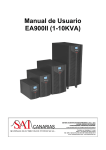
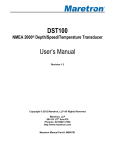
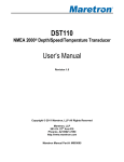
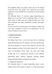
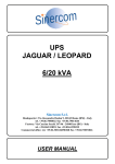
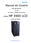
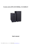
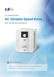
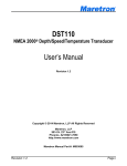
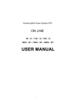
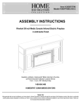
USER MANUAL
On-Line UPS
Model ZS110
6000VA-10000VA
Uninterruptible Power Supply System
1
Contents
1. Brief introduction
1Brief introduction.................................................................1-5
1.1 System and model description....................................................1
1.2 Description of commonly used symbols....................................2
1.3 Appearance...............................................................................2-4
1.4 Product specification and performance......................................5
2. Safety Instruction...................................................................6
3. Installation........................................................................7-14
3.1 Unpacking and inspection...........................................................7
3.2 Input and output power wiring and protective earth ground
installation..............................................................................7-9
3.3 Operating procedure for connecting the long backup time
model UPS with the external battery..................................9-10
3.4 Parallel operation.................................................................10-13
4. Operation and Operating mode.......................................14-20
4.1 Operation..............................................................................14-15
4.2 Operating mode....................................................................15-20
5. Battery maintenance.............................................................21
6. Notes for battery disposal and battery replacement..............22
7. Troubleshooting..............................................................23-24
Appendix 1 Description of Display panel.............................25-26
Appendix2 Indicator and alarm..........................................27-28
8. Chapter Operation (LCD model) ....................................29-39
8.1 Operation Display Panel...............................................................29
8.2 Operation Mode.......................................................................30-34
8.3 Operating Instructions.............................................................34-35
8.4 Checking UPS function.................................................................36
8.5 Troubleshooting.......................................................................37-39
2
1.1 System and model description
The On-Line-Series is an uninterruptible power supply incorporating
double-converter technology. It provides perfect protection specifically for
strict load. The double-converter principle eliminates all mains power
disturbances. A rectifier converts the alternating current from the socket
outlet to direct current. This direct current charges the batteries and powers
the inverter. In the event of power failure, the maintenance-free batteries
power the inverter. Thus the inverter generates a sine wave AC power,
which permanently supplies the loads.
Designed with the proven on-line, double conversion architecture, this
series of UPS offers the greatest degree of availability in power protection
and provides continuous high-quality AC power to connect strict load,
especially for the basic equipments in some areas as: finance,
communication, government, traffic, manufacture, education and so on.
This manual is applicable to the following models:
Type
Standard
Long
back up
time
6KVA
10KVA
6KVAS
10KVAS
10KVAS
12KVAS
15KVAS
20KVAS
Model
6K
10K
6KS
10KS
3C10KS
3C12KS
3C15KS
3C20KS
Input
Single phase + N
Single phase + N
Single phase + N
Single phase + N
Three-phase + N + PE
Three-phase + N + PE
Three-phase + N + PE
Three-phase + N + PE
3
Battery
inbuilt
inbuilt
External battery bank
External battery bank
External battery bank
External battery bank
External battery bank
External battery bank
1.2 Description of commonly used symbols
The following symbols will be used in this manual and may appear during
the course of your practical applications. Therefore, all users should be
familiar with them and understand their meanings.
Notation and Explanation
Notation
Explanation
Alert you to pay special
attention
Caution of high voltage
Notation
Explanation
Protective ground
Alarm silence
Turn on the UPS
Overload indication
Turn off the UPS
Battery check
Idle or shut down the UPS
Alternating current source (AC)
Direct current source (DC)
Recyclable
BACK VIEW of 6K-KS
Do not dispose with
ordinary trash
Battery
1.3 Appearance
BACK VIEW of 10K
BACK VIEW of 6K
4
5
1.4 Product specification and performance
●General specification
Power Rating
Model
6KVA/4.8KW
6KVA/4.8KW
10KVA/8KW
10KVA/8KW
10KVA/8KW
12KVA/9.6KW
15KVA/12KW
20KVA/15KW
6K
6KS
10K
10KS
3C10KS
3C12KS
3C15KS
3C20KS
●
Output
Dimensions Weight
Frequency Input(full load)
(Hz)
Voltage
Current Voltage Current (W*L*H)mm (kg)
50/60 (176-276)VAC 31max 220V/230V 27A 260X560X717 68
50/60 (176-276)VAC 31max 220V/230V 27A 260x533x501 17.5
50/60 (176-276)VAC 50max 220V/230V 45A 260X560X717 70
50/60 (176-276)VAC 50max 220V/230V 45A 260x533x501 19.5
50/60 (304-478)VAC 50max 220V/230V 45A 260X560X717
50/60 (304-478)VAC 60 max 220V/230V 54A 260X560X717
50/60 (304-478)VAC 75 max 220V/230V 68A 260X560X717
50/60 (304-478)VAC 100 max 220V/230V 91A 260X560X717
Electrical performance
Model
6K(S)/S10K(S)
BACK VIEW of 10K-KS
3C10KS/3C12KS/3C15KS
/3C20KS
INPUT
Voltage
Single-phase(220VAC、
230VAC)
Three-phase(380VAC/220
VAC、380VAC/230VAC)
Frequency
Power Factor
50/60Hz±5%
>0.99(Full load)
(adjustable)
50/60Hz±5%
>0.95(Full load)
(adjustable)
Output
Voltage Power
Current
Frequency tolerance Distortion
Overload capacity
crest ratio
regulation factor
Synchronized
105%-125%load transfers
46-54Hz in Line mode THD<2% to bypass mode after 1
3:1
Full load
±1%
0.8lag (AC mode) ±1% of
minutes >130% load
maximum
normal frequency in (Linear load) transfers to bypass mode
Battery mode
after 30second
●Operating environment
Temperature
0°-40°
Humidity
<95%
Altitude
<1000m
Storage temperature
0°-40°
Note: If the UPS is installed or used in a place where the altitude is above
than 1000m, the output power must be decrease in use, please refer
to the following:
BACK VIEW of 3C10K-KS、3C12K-KS、3C15K-KS、3C20K-KS
6
Altitude(M)
Load
1000
100%
1500
95%
2000
91%
2500
86%
7
3000
82%
3500
78%
4000
74%
4500
70%
5000
67%
2. Safety Instruction
3. Installation
●Even if the interruptible Power System (UPS) is not connected to utility
power, the output socket of the UPS may still present 220V/230V output
voltage.
3.1 Unpacking and inspection
●If it is necessary to replace the external battery cord or power cord, please
purchase the original material from the service center or distributor of
our company so as to avoid overheat or spark resulting in fire due to
insufficient capacity.
●Do not let battery or batteries get close to any heating source and do not
incinerate battery or batteries, they may explode.
●Do not open or mutilate the battery or batteries, released electrolyte is
highly poisonous and harmful to the skin and eyes.
●Do not short the positive and negative of battery electrode. Otherwise, it
may cause electric shock or fire.
●To avoid the risk of being shocked, please do not attempt to open the case
of the UPS.
●A battery can present a risk of electric shock and high short circuit
current.
●Do not plug household appliance such as hair dryers to UPS.
1) Unpack the packaging and check the package contents. The shipping
package contains:
●A UPS
●A user manual
●A communication cable
2) Inspect the appearance of the UPS to see if there is any damage during
transportation. Do not turn on the unit and notify the carrier and dealer
immediately if there is any damage or lacking of some parts.
3.2 Input and output power wiring and protective earth ground
installation
3.2.1. Notes for installation
1) The UPS must be installed in a location with good ventilation, far away
from water, inflammable gas and corrosive agents.
2) The UPS should not be tilted. The air inlet port at the lower part of the
front panel and the fan outlet port on the rear panel should not be
blocked so as to ensure good ventilation (Allow at least 0.5m of space on
each side).
3) In case if the UPS is unpacked, installed and used at very low
temperatures, condensation of water drops may appear. It is necessary to
wait until the UPS is fully dried inside out before proceeding to
installation and use. Otherwise, there may be a risk of electric shock.
3.2.2. Installation
Installation and wiring must be performed in accordance with the local
electric code and the following instructions by professional personnel. For
safety, please cut off the mains power breaker before installation. The
battery breaker also needs to be cut off if it is a long backup time model.
1) Open the terminal block cover located on the rear panel of the UPS
(please refer to the appearance diagram).
2) For 6K (S) UPS, it is recommended to select the UL1015 10AWG
(6mm2) wire or other insulated wire which complies with AWG Standard
for the UPS input and output wirings.
8
9
3) For 10K (S)/3C10KS UPS, it is recommended to select the UL1015
8AWG (10mm2) wire or other insulated wire which complies with AWG
Standard for the UPS input and output wirings.
4) For 3C12KS/3C15KS/3C20KS UPS, it is recommended to select the
UL1015 6AWG (25mm2) wire or other insulated wire which complies
with AWG Standard for the UPS input and output wirings.
12) If it is necessary to connect the inductance load such as a monitor or a
laser printer to the UPS, the start-up power should be used for
calculating the capacity of the UPS, as its start-up power consumption
is too big when it is started.
Note: Do not use the wall receptacle as the input power source for the
UPS, as its rated current is less than the UPS’s maximum input
current. Otherwise the receptacle may be burned and destroyed.
(Please refer to section 1.4)
5) Connect the input and output wires to the corresponding input and output
terminals according to the following diagram.
Input and Output Terminal Block wiring diagram of 6K(S)、10K(S)
Note: you must make sure that the input and output wires and the input and
output terminals are connected tightly.
6) The protective earth ground wire refers to the wire connection between
the equipment which consumes electro-equipment and the ground wire.
The wire diameter of protective earth ground wire should be at least as
above mentioned for each model and green wire or green wire with
yellow ribbon wire is used.
7) After having completed the installation, make sure the wiring is correct.
8) Please install the leak current protective breaker at the output power
distribution panel of the UPS if necessary.
9) To connect the load with the UPS, please turn off all the loads first, then
perform the connection and finally turn on the loads one by one.
10) No matter the UPS is connected to the utility power or not, the output
of the UPS may have electricity. The parts inside the unit may still have
hazardous voltage after turning off the UPS. To make the UPS have no
output, power off the UPS, and then disconnect the utility power supply.
11) Suggest charging the batteries for 8 hours before use. After connection,
turn the input breaker in the “ON” position, the UPS will charge the
batteries automatically. You can also use the UPS immediately without
charging the batteries first, but the backup time may be less than the
standard value.
10
Input and Output Terminal Block wiring diagram of
3C10KS/3C12KS/3C15KS/3C20KS
3.3 Operating procedure for connecting the long backup time
model UPS with the external battery
3.3.1. The nominal DC voltage of external battery pack is 192VDC. Each
battery pack consists of 16 pieces of 12V”maintenance-free” batteries in
series. To achieve longer backup time, it is possible to connect
multi-battery packs, but the principle of “same voltage, same type” should
be strictly followed.
3.3.2.For 6KS/10KS/3C10KS/3C12KS/3C15KS/3C20KS,The procedure of
installing battery bank should be complied with strictly. Otherwise you
may encounter the hazardous of electric shock.
11
1) A DC breaker must be connected between the battery pack and the
UPS. The capacity of breaker must be not less than the data specified
in the general specification as follow.
Model
6K
6KS
10K
10KS
3C10KS
Battery
192VDC 192VDC 192VDC 192VDC 240VDC
voltage
Battery
34A max 34A max 56A max 56A max 46A max.
current
3C12KS
3C15KS
3C20KS
240VDC
240VDC
240VDC
56A max.
70A max. 102A max.
Note: 240VDC battery voltage can be choose for 6K(S)/10K(S).
2) Set the battery pack breaker in “OFF” position and connect the 16
pieces of batteries in series.
3.3.3. To complete the connection by plugging the connector of the external
battery cable into the external battery socket of the UPS. Do not attempt to
connect any loads to the UPS now. You should connect the input power
wire to the right position first. And then set the breaker of the battery pack
in the “ON” position. After that set the input breaker in the “ON” position.
The UPS begins to charge the battery packs at the time.
3.4 Parallel operation
3.4.1. Brief introduction of the redundancy
N+X is currently the most reliable power supply structure. N represents the
minimum UPS number that the total load needs; X represents the redundant
UPS number, i.e. the fault UPS number that the system can handle
simultaneously. The bigger the X is, the higher reliability of the power
system is. For occasions where reliability is highly required, N+X is the
optimal mode. As long as the UPS is equipped with parallel cables, up to 3
of them can be connected in parallel to realize output power sharing and
power redundancy.
3.4.2. Parallel installation
1) Users need to opt a standard 25-pin communication cable, which should
have 25 cores, corresponding stitches and shield, as the UPS parallel cable.
The length of the parallel cable is appropriate to be less than 3 m.
2) Strictly follow the stand-alone wiring requirement to perform the input
wiring of each UPS.
12
3) Connect the output wires of each UPS to an output breaker panel first,
and then connect the wiring to the load via the breaker panel.
4) The parallel UPS must be equipped with battery individually.
5) Please refer the figure followed to see the wiring of parallel operation.
The capacity of the breaker must be not less than the specification as
follow.
Model No.
6K(S)
10K(S)/3C10KS
3C15KS/3C20KS
Capacity of breaker
≥40A/250VAC
≥60A/250VAC
≥100A/250VAC
*The requirement of the output wiring is as follows:
●When the distance between the UPSs in parallel and the breaker panel is
less than 20 meters, the difference between the wires of input & output
of the UPSs is required to be less than 20%;
●When the distance between the UPSs in parallel and the breaker panel is
greater than 20 meters, the difference between the wires of input &
output of the UPSs is required to be less than 10%.
3.4.3. Operation and maintenance
1) To perform the general operation, follow the stand-alone operating
requirement;
2) Start up: The units transfer to INV mode simultaneously as they start up
sequentially in utility power mode;
Shutdown: the units shut down sequentially in INV mode. When the last
one completes the shutdown action, each unit will shut down the inverter
simultaneously and transfer to bypass mode.
3) To perform the maintenance, follow the stand-alone requirement.
13
14
15
4. Operation and Operating mode
It is easy to operate the equipment, with no previous training. You just need
to read through this manual and operate according to the instructions in it.
The meaning of the LED indicators, please refer to the appendix 1 “Display
panel”.
LED will be turned on. The UPS is working in Bypass mode.
3) Upon completion of the above to turn it off, output of electric current of
the UPS is still present. In order to cut off the output from the UPS,
simply cut off the utility power supply and the UPS will perform
self-diagnosis, finally not any display is shown on the display panel and
no voltage output is available from the UPS output.
4.1 Operation
4.1.4. Turn off the UPS with no utility power supplied
4.1.1. Turn on the UPS with utility power supplied
1) After you make sure that the power supply connection is correct, set the
input breaker in the “ON” position first. At this time the fan rotates and
the UPS supplies power to the load via the bypass. The UPS operates in
Bypass mode.
2) To power on the UPS by simply pressing the “ON” button continuously
for more than 1 second.
3) When being powered on, the UPS will perform self-diagnosis, with the
load/battery level LEDs turned on and then off one after another in
ascending order. A few seconds later, the INV LED is turned on, the
UPS is already running in Utility Power mode. If the utility power is
abnormal, the UPS will operate in battery mode without output
interruption of the UPS.
1) Press the “OFF” button continuously for more than 1 second to power
off the UPS.
2) When being powered off, the UPS will perform self-diagnosis, the
Load/Battery level LEDs will be turned on and then off one after
another in ascending order. Finally not any display is shown on the
display panel and no voltage is available from the UPS output.
Suggestions:
Please turn off the connected loads before turning on the UPS and turn on
the loads one by one after the UPS is working in INV mode. Turn off all of
the connected loads before turning off the UPS.
4.2 Operating mode
4.1.2. Turn on the UPS with no utility power supplied
4.2.1. Normal power mode
1) Press the “ON” button continuously for more than 1 second to power on
the UPS. For long back up time model (“L” model), please make sure
that the battery breaker is in “ON” position.
2) During the course of starting up, the UPS has the same action as if it is
connected to utility power except that the utility power LED is not turned
on and the battery LED is turned on instead.
In the normal mode, the display on the front panel is shown in the
following diagram. The utility power indicator and the Inverter indicator
are turn on.
The load/battery capacity indicator will be turned on in accordance with the
load capacity connected.
1. If the utility power indicator blinks, it indicates that there are problems
with reversed polarity (L, N) of site wiring or disconnect with ground
that may result in shock hazard. UPS is still working in normal mode. If
the battery indicator is turn on at the same time, it shows that the voltage
or frequency of the utility power is out of the normal input range of the
UPS. The UPS works in battery mode.
4.1.3. Turn off the UPS with utility power supplied
1) Press the “OFF” button continuously for more than 1 second to turn off
the inverter of the UPS immediately.
2) When being powered off, the UPS will perform self-diagnosis, the
Load/Battery level LEDs will be turned on and then off one after another
in ascending order, then the INV LED will be turned off and Bypass
16
17
utility power indicator blinks at the same time, it shows that the utility
power is abnormal. The load/battery capacity indicators will be turn on in
accordance with the battery capacity. Please note that the load/battery
capacity indicator in normal mode will indicate the battery capacity in
battery mode.
1. When the ups is running in battery mode, the alarm will beep every 4
seconds. If the “Function” key is pressed for more than 5 seconds, the
alarm will not beep (silence function). Press the “Function” key more
than 5 seconds again to resume the alarm function.
Figure 4-1 Normal Mode
2. If output overloaded, the load level indicators will be turned on and
alarm will beep every second. You should get rid of some unnecessary
loads one by one to decrease the loads connected to the UPS less than
95% capacity of the UPS.
3. If the battery indicator blinks, it indicates that no battery is connected to
the UPS or battery voltage is too low. You should check if battery is
properly connected to the UPS, and press function button more than 5
seconds to start the battery self-diagnosis. If the connection between
battery and UPS is confirmed without any problem, it may be due to the
defect or aging of the battery, please refer to the “troubleshooting” in
chapter 7 to solve the problem accordingly.
Note:Connection to the power generator should be made according to the
following steps:
l Activate the power generator and wait until the operation is stable
before connecting the output of the power generator to the UPS (be
sure that the UPS is in idle mode). Then, turn on the UPS according to
the startup procedure. After the UPS is turned on, the loads are
connected one by one.
l It recommended that the capacity of the AC generator chosen should
double that of the UPS.
4.2.2 Battery mode
In battery mode the display on the front panel is shown in the following
diagram. The battery indicator and the inverter indicator are turn on. If the
18
Figure 4-2 Battery Mode
2. When the battery capacity decreases, the number of load/battery capacity
indicators turned on will decrease. If the battery voltage drops to the
pre-alarm level (capable of maintaining the backup time for more than 2
minutes), the alarm will beep every second to remind the user of
insufficient battery capacity.
4.2.3 Bypass mode
When operating in bypass mode set up through UPSilon software, the
display on the front panel is show in the following diagram. The utility
power indicator and the bypass indicator are turn on. The load/battery
capacity indicator will be turned on in accordance with the load capacity
connected.
1. If the utility power indicator blinks, it shows that the voltage or
frequency of the utility power is out of the input range of the UPS or
there are problems with reversed polarity (L/N) of site wiring or
19
disconnect to the ground for protection.
2. When operating in bypass mode, the UPS beeps every 2 minutes, If the
“Function” key is pressed for more than 5 seconds, the alarm will not
beep(silence function). Press the “Function” key more than 5 seconds
again to resume the alarm function.
Notes: When operating in bypass mode, the backup function of the UPS is
not available and the power used by the load is directly from the utility
power via internal EMI filter.
4.2.6. Internet Communication
Figure 4-3 Bypass Mode
4.2.4. Abnormality mode
In case the fault LED is turned on when the UPS is in use, it shows that the
UPS is operating in abnormal mode. Please refer to the troubleshooting in
section 7 for details.
4.2.5. Backup time for the standard model
The backup time of the long backup time model is dependent on the
external battery pack capacity and the load level as well as other factors.
The backup time of standard model may vary from different models and
load level.
Please refer to the following:
This series is equipped with an intelligent slot for Web power (optional
accessory) or other optional card to achieve remote management of the
UPS. Please contact your local distributor for further information.
4.2.7. Description of communication interface
1) The standard RS232 port is applicable to communicate with computer.
Description and pin assignment of RS232
Baud rate: 2400bps
Data bit: 8 bit
Ending bit: 1bit
Parity bit: None
DB-9 pin assignment:
RS232 Interface
20
21
Pin number
3
2
5
Function description
Rxd
Txd
GND
I/O
Input
Output
Ground
2) User enables to monitor and manage the UPS through installed the
AS400 card (optional).
PIN1: UPS failure (normally open, active close)
PIN2: summary alarm
PIN3: ground
PIN4: Remote shutdown
PIN5: Common
PIN6: Bypass active (relay close)
PIN7: Battery low
PIN8: UPS On (relay close)
PIN9: Utility Power failure (normally open, active close)
5. Battery maintenance
●This series UPS only requires minimal maintenance. The battery used for
standard models is valve regulated sealed lead-acid maintenance free
battery. These models require minimal repairs. The only requirement is to
charge the UPS regularly in order to maximize the expected life of the
battery. When being connected to the utility power, whether the UPS is
turned on or not, the UPS keeps charging the batteries and also offers the
protective function of overcharging and over discharging.
●The UPS should be charged once every 4 to 6 months if it has not been
used for a long time. In the regions of hot climates, the battery should be
charged and discharged every 2 months. The standard charging time
should be at least 12 hours.
●Under normal conditions, the battery life lasts 3 to 5 years. In case if the
battery is found not in good condition, earlier replacement should be made.
Battery replace event should be performed by qualified personnel.
●Replace batteries with the same number and same type of batteries.
●Keep the ambient temperature between 15
and 25
●Do not replace the battery individually. All the batteries should be
replaced at the same time following the instructions of the battery
supplier.
AS400 Interface
22
●Normally, the batteries should be charged and discharged once every 4 to
6 months. Charging should begin after the UPS shuts down automatically
in the course of discharging, the standard charging time for the standard
UPS should be at least 12 hours. Discharge the battery with the load more
than 50%.
23
6. Notes for battery disposal and battery replacement
1) Before disposing batteries, remove conductive articles such as necklace,
wrist watches and rings.
2) If it is necessary to replace any connection cables, please purchase the
original materials from the authorized distributors or service centers, so
as to avoid overheat or spark resulting in fire due to insufficient capacity.
7.Troubleshooting
Problem
Possible cause
The 1# Fault LED
and the 6 #LED are
turned on, the buzzer
beeps continuously
The UPS
shutdown due to
internal overheat
The 1# Fault LED
and the 2# and5 #
LED are turned on,
and the buzzer beeps
continuously
The UPS output
is Short circuited.
3) Do not dispose of batteries or battery packs in a fire, they may explode.
4) Do not open or mutilate batteries, released electrolyte is highly
poisonous and harmful to the skin and eyes.
5) Do not short the positive and negative electrodes of the battery,
otherwise, it may result in electric shock or fire.
6) Make sure that there is no voltage before touching the batteries. The
battery circuit is not isolated from the input potential circuit. There may
be hazardous voltage between the battery terminals and the ground.
7) Even though the input breaker is disconnected, the components inside
the UPS are still connected with the batteries, and there are potential
hazardous voltages. Therefore, before any maintenance and repairs work
is carried out, switch off the breaker of the battery pack or disconnect the
jumper wire of connecting between the batteries.
8) Batteries contain hazardous voltage and current. Battery maintenance
such as the battery replacement must be carried out by qualified
personnel who are knowledgeable about batteries. No other persons
should handle the batteries.
24
The 1# Fault LED
and the 4# LED are
turned on, the UPS
beeps continuously
The 1# Fault LED
and the 5# LED are
turned on, the UPS
beeps continuously
Solution
Make sure the UPS is not
overloaded; the air vents are not
blocked and the ambient
temperature is not too high. Wait
for 10 minutes for the UPS to cool
down before turning on again. If
failed, please contact the distributor
or service center.
Turn off the UPS. Remove all the
loads. Ensure that the load is not
failed or the UPS has no internal
faults before turning it on again. If
failed, please contact the
distributor or service center.
The UPS shuts
down due to its
internal fault.
Please contact the distributor or
service center.
The UPS shuts
down due to its
internal fault.
Please contact the distributor or
service center.
The utility power
LED flashes
The voltage or
frequency of the
utility power is
out of the input
range of the
UPS.
The UPS is running in battery
mode. To save your data and close
the application program. Make
sure the utility power is within the
input voltage or frequency range
permitted by the UPS.
The 1# Fault LED
and the 2# LED are
turned on, the UPS
beeps continuously
The UPS is
overloaded or the
load equipment is
faulty
Check the loads and remove all no
critical equipment. Recalculate the
load power and reduce the number
of loads connected to the UPS.
Check that the loads are not failed.
The 1# Fault LED
and the battery LED
are turned on, the
buzzer beeps every
second
The charger of
the UPS is
defective.
Please contact the distributor or
service center.
25
Appendix 1 Description of Display panel
7.Troubleshooting
Problem
Possible cause
Battery LED flashes
Battery low
The utility power is
normal, but the UPS
can not turn in line
mode
AC input breaker in
“OFF” position
Battery not yet been
fully charged
Battery discharging
time diminishes
UPS overloaded
Battery aged
The UPS cannot
power on after
pressing the “ON”
button
The “ON” button is
pressed too briefly
The UPS is not
connected to the
battery or the battery
pack voltage is too low.
UPS internal fault
Solution
Check the battery. If the
battery is damaged, replace
the battery immediately and
ensure that the battery breaker
is in “ON” position.
Set the input breaker in “ON”
position
Keep UPS connected to utility
power persistently for more
than 10 hours to recharge the
batteries again.
Check the loads and remove
the non-critical equipment.
Replace the batteries. Please
contact the distributor to
obtain the parts and
replacement service.
Press the “ON” button for
more than 1 second.
Check the battery or recharge
the battery.
Please connect the distributor
or service center.
When you contact the service center, please provide the following
information:
●Model No. and the serial No. of the UPS;
●The date when the problem arose;
●Complete description of the problem, including the LED display, alarm
warning, power condition and load capacity. If your UPS is a long
backup time model, you may also provide the battery information.
26
1. ON button:
Pressing the ON/OFF button more than 1 second, the UPS system is turned
on.
2. OFF button:
By pressing this button more than 1 second turns off the UPS system
whenever the UPS run under the normal mode/battery mode.
3. Function button
The Function button provides the following functions:
1) Battery self- diagnosis: When the UPS ran in normal mode, pressing this
button more than 5 seconds (buzzer beeps twice) can start the battery
self-diagnosis.
2) Silence function in battery/bypass mode
In battery/bypass mode, when the buzzer beeps, pressing and holding the
function button for more than 5 seconds (buzzer beeps one times) can
silence the buzzer. Press the button for more than 5 seconds (buzzer
beeps twice) again to resume the alarm function.
Note: The alarm silencing function of the Function button is valid only in
battery mode, and invalid for any other UPS alarm.
4. LED indicators
The LEDs contains Fault indicator, Load/battery capacity indicator,
Bypass indicator, utility power indicator, Inverter indicator, Battery
indicator.
27
Appendix 1 Description of Display panel
Appendix2 Indicator and alarm
Table Appendix 1 Description of indicators
No.
No.
Color
Indicator
1#
Red
Fault indicator
2#
3#
4#
5#
Orange
Green
Green
Green
Load/battery capacity indicator
Load/battery capacity indicator
Load/battery capacity indicator
Load/battery capacity indicator
6#
Green
Load/battery capacity indicator
7#
Orange
Bypass indicator
8#
Green
Utility power indicator
9#
Green
Inverter indicator
10#
Orange
Battery indicator
Description
When the indicator on, it shows that
the UPS in abnormal condition.
Show the capacity of load/battery:
1.Indicate the percentage of the load
capacity in normal mode and bypass
mode
2. Indicate the battery capacity level in
battery mode.
When the indicator on, it shows that
the loading current is supplied from the
utility power directly
When the indicator on, it shows that
the utility power is normal.
When the indicator on, it shows that
the load current is supplied from utility
power or battery via the inverter.
When the indicator on, it shows that
the load current is supplied from
battery via the inverter.
4
5
6
7
8
9
10
Battery
mode
3
#
LED indicators
4 5 6 7 8
# # # # #
Audible alarm
● ●
● ●
none
51%--75% Load
● ● ●
● ●
none
●
● ● ●
● ●
none
● ●
● ● ●
● ●
none
76%--100%
Load
101%--105%
Load
0~20%
battery capacity
21%~40%
battery capacity
41%~60%
battery capacity
61%~80%
battery capacity
81%~100%
battery capacity
Bypass mode
★ ↑
↑
Beep once
every sec
Beep once
every 4 sec.
Beep once
every 4 sec.
Beep once
every 4 sec.
Beep once
every 4 sec.
Beep once
every 2 min.
Beep twice
every sec
Beep twice
every sec
none
★ ↑
↑
↑
none
↑
●
●
●
●
●
● ●
●
●
● ●
●
●
●
● ●
● ●
●
●
● ●
● ● ●
●
●
↑
↑
↑
↑
14
15
Bypass mode abnormal
16
Overload in Battery mode,
pre-alarm
17
Overload fault
18
Overheating fault
●
19
Inverter fault
●
●
20
Output short circuit
● ●
●
13
10
#
26%--50% Load
Overloaded in Normal
mode
Overloaded in bypass
mode
Utility power abnormal
12
9
#
none
2
Normal
mode
2
#
● ●
0%--25%Load
3
1
#
●
1
11
28
Operating status
●
● ●
● ●
● ● ●
● ●
● ● ●
● ●
↑
↑
↑
↑
↑
↑
↑
↑
↑
↑
↑
● ↑
↑
↑
↑
● ●
● ●
↑
●
29
↑
↑
↑
↑
↑
Beep twice
every sec
Sustained
beep
Sustained
beep
Sustained
beep
Sustained
beep
8 Chapter Operation (LCD model)
No.
Operating status
1
#
21
BUS voltage fault
●
22
Charger or battery fault
●
23
Fan failure
24
2
#
3
#
LED indicators
4 5 6 7 8
# # # # #
9
#
10
#
Audible alarm
↑
↑
↑
★
↑
↑
↑
↑
Sustained
beep
Beep once
every sec
Beep once
every sec
Sustained
beep
Sustained
beep
Beep once
every sec
Sustained
beep
↑
★ ↑
↑
Beep once
every sec
↑
↑
● ●
↑
↑
● ● ●
●
↑
↑
●
●
●
↑
↑
● ●
● ● ●
↑
Inv Rly Stick Fault
●
●
●
↑
↑
37
Inv Rly Open Fault
●
● ●
↑
↑
38
Line SCR Fault
●
● ● ●
↑
↑
39
Line In Fuse Open Fault
●
●
↑
↑
●
↑
↑
↑
↑
● ●
●
↑
↑
Parallel fault
● ● ●
●
↑
↑
25
ID repetition
● ●
27
BAT voltage low
↑
28
Over Charger
●
29
Reversed polarity (L, N) of
input wiring or
disconnected with ground.
30
BAT fault
●
31
EPO mode
↑
32
Bus short
●
33
Negtive power fault
34
React Power Fault
35
Power Fault
36
↑
↑
↑
↑
↑
↑
●
●
↑
↑
●
●
:Flash
30
↑
↑
↑
↑
●
↑
LED indictor description: ●:O n
●
↑
↑
↑
●
↑
Sustained
beep
Beep once
every sec
Sustained
beep
Sustained
beep
Sustained
beep
Sustained
beep
Sustained
beep
Sustained
beep
Sustained
beep
Sustained
beep
↑:Depending on other conditions
8.1 Operation Display Panel
1. ON button:
Pressing the ON button more than 1 second (buzzer beeps once), the UPS
system is turned on.
2. OFF button:
By pressing this button more than 1 second (buzzer beeps once) turns off
the UPS system whenever the UPS run under the normal mode/battery
mode.
3. Function button
The Function button provides the following functions:
a) Battery self- diagnosis: When the UPS ran in normal mode, pressing this
button more than 5 seconds (buzzer beeps twice) can start the battery
self-diagnosis.
b) Silence function in battery/bypass mode
In battery/bypass mode, when the buzzer beeps, pressing and holding the
function button for more than 5 seconds (buzzer beeps two times) can
silence the buzzer. Press the button for more than 5 seconds (buzzer
beeps twice) again to resume the alarm function
c) LCD display screen switch
Pressing the function button for more than 1 seconds (buzzer beeps once)
to switch LCD display screen
4. LED indicators
The LED indicators contains Fault indicator, Bypass indicator, utility
power indicator, Inverter indicator, Battery indicator. The definition of
each indicator is the same as LED panel (refer to table Appendix 1).
31
8.2 Operation Mode
UPS Operation Mode contains normal mode, battery mode and bypass
mode. Under the three modes, the page showing output voltage and output
frequency is the main display page. If users need more information about
UPS, Pressing the function button can initiate display screen switch. If the
current page is not the main page, UPS will auto switch back the main page
after 30 seconds. In order to extend the LCD usage life, the backlight will
turn off after 1 minute without any switch operation. At this point, Users
just need to touch any button briefly, the backlight will be turn on.
8.2.1 Normal mode
When operating in the normal mode, the display of main page on the front
panel is shown as the figure 8-2. The utility power indicator and the
Inverter indicator are turn on. Load information area shows load value, and
the battery level area indicates dynamically when the battery is not full
charged (the battery level icons lit one after another circularly). When the
battery is full charged, all the level icons are turn on.
1) If the utility power indicator blinks, it indicates that there are problems
with reversed polarity (L, N) of site wiring or disconnect with ground.
UPS is still working in normal mode. If the battery indicator is turn on at
the same time, it shows that the voltage or frequency of the utility power
is out of the normal input range of the UPS. The UPS works in battery
mode.
2) If load is more than 105 percent, the buzzer beeps twice every second,
meanwhile, the warning icon blinks every second too, reminding that
you have been overloaded. You should get rid of some unnecessary loads
one by one to decrease the loads until the alarm clear
3) If the battery indicator blinks, it indicates that no battery is connected to
the UPS or battery voltage is too low. You should check if battery is
properly connected to the UPS, and press function button more than 5
seconds to start the battery self-diagnosis. If the connection between
battery and UPS is confirmed without any problem, it may be due to the
defect or aging of the battery, please refer to the “troubleshooting” in
chapter 7 to solve the problem accordingly.
4) The other four display pages are load percent page, actual load page,
input information page and the maximum temperature page.
Note:Connection to the power generator should be made according to the
following steps:
l Activate the power generator and wait until the operation is stable
before connecting the output of the power generator to the UPS (be
sure that the UPS is in idle mode). Then, turn on the UPS according to
the startup procedure. After the UPS is turned on, the loads are
connected one by one.
l It recommended that the capacity of the AC generator chosen should
double that of the UPS.
8.2.2 Battery Mode
When operating in the normal mode, the display of main page on the front
panel is shown as the figure 8-3. The battery indicator and the Inverter
indicator are turn on. If the utility power indicator blinks at the same time,
it shows that the utility power is abnormal. Load information area shows
load value, and bat level area shows current battery capacity.
1) When the UPS is running in battery mode, the alarm will beep every 4
seconds. If the “Function” key is pressed for more than 5 seconds, the
alarm will not beep (silence function). Press the “Function” key more
than 5 seconds again to resume the alarm function.
Figure 8-2 Normal Mode
32
33
3) The other four display pages are load percent page, actual load page,
input information page and the maximum temperature page.
Notes: When operating in bypass mode, the backup function of the UPS is
not available and the power used by the load is directly from the
utility power via internal EMI filter.
Figure 8-3 Battery Mode
2) When the battery capacity decreases, the number of load/battery capacity
indicators turned on will decrease. If the battery voltage drops to the
pre-alarm level (capable of maintaining the backup time for more than 2
minutes), the alarm will beep every second to remind the user of
insufficient battery capacity.
3) The other four display pages are load percent page, actual load page,
battery information page and the maximum temperature page.
8.2.3 Bypass Mode
When operating in bypass mode set up through UPSilon software, the
display on the front panel is shown as the figure 8-4, the utility power
indicator and the bypass indicator are turn on. The load/battery capacity
indicator will be turned on in accordance with the load capacity connected.
Load information area shows load value, and the battery level area
indicates dynamically when the battery is not full charged (the battery level
icons lit one after another circularly). When the battery is full charged, all
the level icons are turn on.
1) When operating in bypass mode, the UPS beeps every 2 minutes. If the
“Function” key is pressed for more than 5 seconds, the alarm will not
beep (silence function). Press the “Function” key more than 5 seconds
again to resume the alarm function.
2) If the utility power indicator blinks, it shows that the voltage or
frequency of the utility power is out of the input range of the UPS or
there are problems with reversed polarity (L/N) of site wiring or
disconnect to the ground for protection.
34
Figure 8-4 Bypass Mode
8.2.4 LCD indication of UPS alarm status and faults
In the event of an UPS fault, UPS enters fault operation mode, at this point,
the fault icon turn on consistently, the buzzer beeps continuously and the
data information area shows current fault code (refer to table 8.5-1), the
display on the front panel is shown as the figure8-5.
Figure 8-5 Fault display
35
When a warning occurred, the fault icon blinks every second, and users can
switch to the alarm display page shown as the figure 8-6 to check the
warning code.
Figure 8-6 Alarm display
8.3 Operating Instructions
8.3.1 UPS ON/OFF Operation
Note: The battery is fully charged before delivery. However, storage and
transportation will inevitably cause some charge loss. Therefore, it
is advisable to charge the battery for 10 hours before using it, so as
to ensure adequate battery autonomy.
indicate that the UPS is working in battery mode.
2. Powering down the UPS
The operation of powering down the UPS contains: turning off ups in
normal mode, turning off ups in battery mode
1) Completely power down the UPS from Normal mode
Hold and press the OFF button persistently for more than 1 second to
power off the UPS. If it bas been set up to work in bypass mode by
software, the bypass indicator will be turn on to indicate that the UPS is
working in bypass mode. In order to cut off the output from the UPS,
simply cut off the utility power supply. LCD begins to conduct
self-diagnosis (all the LCD indicators are turn on about 4 seconds),
seconds later, not any display is shown on the front panel and no output
is available from the UPS outlets, system completely power down.
2) Completely power down the UPS from Battery mode
Press the “OFF” button persistently for more than 1 second to power off
the UPS. When being powered off, the LCD will start self-diagnosis (all
the LCD indicators are turn on about 4 seconds), seconds later, not any
display is shown on the front panel and no voltage output is available
from the UPS outlets, system completely power down.
8.3.2 Conducting Battery self-diagnosis
1. Turning on the UPS
The operation of turning on the UPS contains: turning on with utility power
and turning on without utility power.
1) Turning on with utility power:
Connect the mains input to the UPS, press the ON button more than one
second, UPS start to turn on. At this point, the LCD begins to conduct
self-diagnosis (all the LCD indicators are turn on about 4 seconds).
Seconds later, the UPS will begin to operate in Normal mode; meanwhile,
the utility power indicator, inverter indicators will turn on. If the utility
power is abnormal, the UPS will work in battery mode.
In UPS operation, users can manually initiate battery self-diagnosis to
check the battery conditions. There are two methods to initiate the battery
self-diagnosis:
1. Through the function button
In normal mode, press and hold the function for more than 5 seconds
until the buzzer beeps twice. At this point the indicators (LED7~10) will
blink cyclically, indicating the UPS has worked in battery mode and the
battery self-diagnosis has started. The battery self-diagnosis will last for
5 seconds default. In the event of a battery fault during battery
self-diagnosis, the UPS will transfer to normal mode automatically.
2) Turning on without utility power:
With no mains input feed to the UPS, press the ON button more than one
second, ups start to turn on, At this point, the LCD begins to conduct
self-diagnosis (all the LCD indicators are turn on about 4 seconds).
Seconds later, the battery indicator, inverter indicators will be turn on to
2. Through the monitor software
Users can also initiate battery self-diagnosis through the background
monitoring software.
36
37
8. 4Checking UPS function
8 Chapter Operation (LCD model)
Every time when conducting field maintenance, please check the regular
function of the UPS, including:
1. Check the operation status of the UPS
If the main voltage is within the specifications, the UPS should operate
in normal mode; if the main voltage is abnormal, the UPS should operate
in battery mode. In both cases, there should be no fault indication.
2. Check the transfer between the UPS operation modes
Disconnect the main input to simulate a mains failure, the UPS should
transfer to battery mode and operate normally; then recover the mains
input, the UPS should transfer to normal mode and operate normally
3. Check the LED indicators of the UPS
During the check processes stated above, check that the LED indication
of the UPS agrees with the UPS operation mode.
8.5 Troubleshooting
In the event of an UPS fault, shoot the trouble according to Table8.5-1. If
the fault still persists, please contact our customer service center.
Faults
Fault/
Warning
code
F01
F02
F03
F05
F06
F07
F08
F10
F17
F21
F25
F26
F29
F32
38
Fault icon
Alarm
Possible
cause
on
constantly
on
constantly
on
constantly
on
constantly
on
constantly
on
constantly
on
constantly
Beep
continuously
Beep
continuously
Beep
continuously
Beep
continuously
Beep
continuously
Beep
continuously
Beep
continuously
Internal
fault.
Internal
fault.
Internal
fault.
Internal
fault.
Internal
fault.
Internal
fault.
Internal
fault.
on
constantly
Beep
continuously
The UPS
output is
short
circuited
on
constantly
on
constantly
on
constantly
on
constantly
on
constantly
on
constantly
Beep
continuously
Beep
continuously
Beep
continuously
Beep
continuously
Beep
continuously
Beep
continuously
Internal
fault.
Internal
fault.
Internal
fault.
Internal
fault.
Internal
fault.
parallel line
loss
39
Solution
Please contact the distributor
or Service center
Please contact the distributor
or Service center
Please contact the distributor
or Service center
Please contact the distributor
or Service center
Please contact the distributor
or Service center
Please contact the distributor
or Service center
Please contact the distributor
or Service center
Turn off the UPS. Remove
all loads. Ensure that the
loads are not failed or the
UPS has no internal short
before turn on it again. If
failed, please contact the
distributor or service center
Please contact the distributor
or Service center
Please contact the distributor
or Service center
Please contact the distributor
or Service center
Please contact the distributor
or Service center
Please contact the distributor
or Service center
Please check parallel line
connect or not.
8 Chapter Operation (LCD model)
Faults
Fault/
Warning
code
F34
F35
F36
F42
F57
Fault icon
on
constantly
on
constantly
on
constantly
on
constantly
on
constantly
Possible
cause
Alarm
Beep
continuously
Beep
continuously
Beep
continuously
Beep
continuously
Beep
continuously
Internal
fault.
Internal
fault.
Internal
fault.
Internal
fault.
Battery fault
Faults
Solution
Please contact the
distributor or Service center
Please contact the
distributor or Service center
Please contact the
distributor or Service center
Please contact the
distributor or Service center
Please contact the
distributor or Service center
Fault/
Warning
code
A15
A16
A18
A20
A04
A05
A07
A08
A10
A11
A12
A14
Blink once
every
second
Blink once
every
second
Blink once
every
second
Blink once
every
second
Blink once
every
second
Blink once
every
second
Blink once
every
second
Blink once
every
second
No beep
Line fail
No beep
Please check line voltage
A33
ground line
unconnected
Please check ground line
connect or not.
A34
Beep once
every two
minutes
reversed
polarity
(L,N) of site
wiring
Please check the polarity of
the neutral wiring and the
line wiring
A35
No beep
By pass fail
Please check line voltage
Beep once
every
second
Beep once
every
second
Batteries
unconnected
Battery
voltage low
Please check battery line
connect or not.
The UPS output will be cut
off, please switch to the
backup power.
Beep
continuously
Battery
overcharging
Please contact the
distributor or Service center
Beep twice
every
second
Overload
pre-warning
Reduce the member of
loads connected to the UPS.
40
A53
A61
Fault icon
Blink once
every
second
Blink once
every
second
Blink once
every
second
Blink once
every
second
Blink once
every
second
Blink once
every
second
Blink once
every
second
Blink once
every
second
Blink once
every
second
Possible
cause
Solution
Alarm
Beep
continuously
Overload
fault
Reduce the member of
loads connected to the
UPS.
Beep once
every
second
Fan failure
Ensure that the fan is not
locked
Beep
continuously
Charger fail
Please contact the
distributor or Service
center
No beep
Start UPS
fail
Please check the battery
cables connect or not.
No beep
Parallel mode
fault
No beep
Eeprom fault
Beep
continuously
ID repetition
Beep
continuously
Unrecognized
UPS model
Beep
continuously
Slave PSDR
fault
Please contact the
distributor or Service
center
Please contact the
distributor or Service
center
Please contact the
distributor or Service
center
Please contact the
distributor or Service
center
Please contact the
distributor or Service
center
Table 8.5-1 UPS troubleshooting of LCD panel indicator
When you contact the service center, please provide the following
information:
● Model No and Serial No of the UPS.
● The date when the problem arose.
● Complete description of the problem, including the panel display, alarm
warning, and power condition and the load capacity. If the UPS is a long
backup time model, you may also provide the battery information.
41