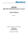
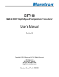
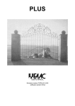
1
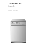
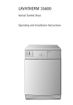
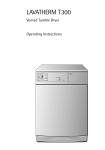
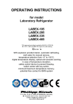
0.4~22kW(200V/400V) AC Variable Speed Drive iG5A Troubleshooting Manual Safety Instructions Read this manual carefully before servicing or inspecting this equipment. Keep this manual within easy reach for quick reference. Quick Reference Table The following table contains situations frequently encountered by users while working with inverters. Refer to the typical and practical situations in the table to quickly and easily locate answers to your questions. Situation Reference The motor is too noisy. P. 32 I want to review recent fault trip and warning histories. P. 15 The motor runs too hot. P. 29 The cooling fan does not work. P. 33 I want to know how can I keep the inverter when I don`t use it. P. 44 ERR message is displaying on keypad. P. 19 I want to initialize the parameter. P. 13 I want to scrap the inverter. P. 44 I want to review the input/output module. P. 38 I want to change the FAN when it exceed replacement period P. 42 I want to change the carrier frequency. P. 12 I cannot set the parameter. P. 28 The motor does not work. P. 32 The motor stop when it accelerate the speed or connect the load. P. 30 1 Contents INTRODUCTION Manual Composition 3 PRODUCT IDENTIFICATION ASSOCIATION MANUAL SAFETY INFORMATION 4 4 5 7 REVISION RECORD 1 BASIC CHECKLIST 3 8 1.1 Before You Think It Is Failure 1.2 Basic Operations 1.3 Parameter Change 8 10 12 1.3.1 Carrier Frequency Change 1.3.2 Initializing All Parameters 1.3.3 Read and Write Parameters 12 13 14 1.4 Fault Trip Monitoring 15 2 TROUBLESHOOTING 18 2.1 Trips and Warnings 18 2.1.1 Fault/Warning List 2.1.2 Troubleshooting Fault Trips 19 21 2.2 Troubleshooting Other Faults 28 3 MAINTENANCE 34 3.1 Regular Inspection Lists 35 3.1.1 3.1.2 3.1.3 3.1.4 3.1.5 35 36 37 38 42 Daily Inspections Annual inspections Bi-annual Inspections Checking the Input/Output Modules Replacement of the cooling fan 3.2 Storage and disposal 44 3.2.1 Storage 3.2.2 Disposal 44 44 2 Introduction Manual Composition 1 Basic Checklist Basic Checklist 1.1 Before You Think It Is Failure When the problem of inverter occur, you can check the basic checklist before you think it is failure in these pages. 1.2 Basic Operations 1.3 Parameter Change 1.3.1Carrier Frequency Change 1.3.2Initializing All Parameters 1.3.3Read and Write Parameters check the set-up of parameter using basic operations first and then check the trip record. 1.4 Fault Trip Monitoring 2 Troubleshooting There are troubleshooting fault trips & other faults in these pages. If problems are not resolved, please contact your vendor or LSIS. 2.1 Trips and Warnings 2.1.1Fault/Warning List 2.1.2Troubleshooting Fault Trips 2.2 Troubleshooting Other Faults 3 Maintenance 3.1 Regular Inspection Lists 3.1.1Daily Inspections 3.1.2Annual inspections 3.1.3Bi-annual Inspections 3.1.4Checking the Input/Output Modules 3.1.5 Replacement of the cooling fan There are the regular inspection lists in these pages. When the problem of inverter occur, please check the input/output module that is basic hardware check method. 3.2 Storage and disposal 3.2.1Storage 3.2.2Disposal 3 Product Identification Model name Power source specifications Output specifications SV 055 iG5A - 2 Motor capacity 004-0.4kw 008-0.75kw 015-1.5kw 022-2.2kw 037-3.7kw 040-4.0kw 055-5.5kw 075-7.5kw 110-11.0kw 150-15.0kw 185-18.5kw 220-22.0kw Series name Input voltage 1- Single phase 200~230[V] 2- 3 phase 200~230[V] 4- 3 phase Association Manual iG5A user manual can be download through the homepage of LSIS. Link : http://www.lsis.com/support/download/ 4 Safety Information Read and follow all safety instructions in this manual precisely to avoid unsafe operating conditions, property damage, personal injury, or death. Safety symbols in this manual Danger Indicates an imminently hazardous situation which, if not avoided, will result in severe injury or death. Warning Indicates a potentially hazardous situation which, if not avoided, could result in injury or death Caution Indicates a potentially hazardous situation that, if not avoided, could result in minor injury or property damage. Safety information Danger Do not open the cover of the equipment while it is on or operating. Likewise, do not operate the inverter while the cover is open. Exposure of high voltage terminals or charging area to the external environment may result in an electric shock. Do not remove any covers or touch the internal circuit boards (PCBs) or electrical contacts on the product when the power is on or during operation. Doing so may result in serious injury, death, or serious property damage. Do not open the cover of the equipment even when the power supply to the inverter has been turned off unless it is necessary for maintenance or regular inspection. Opening the cover may result in an electric shock even when the power supply is off. The equipment may hold charge long after the power supply has been turned off. Use a multi-meter to make sure that there is no voltage before working on the inverter, motor or motor cable. 5 Warning This equipment must be grounded for safe and proper operation. Do not supply power to a faulty inverter. If you find that the inverter is faulty, disconnect the power supply and have the inverter professionally repaired. The inverter becomes hot during operation. Avoid touching the inverter until it has cooled to avoid burns. Do not allow foreign objects, such as screws, metal chips, debris, water, or oil to get inside the inverter. Allowing foreign objects inside the inverter may cause the inverter to malfunction or result in a fire. Do not operate the inverter with wet hands. Doing so may result in electric shock. Caution Do not modify the interior workings of the inverter. Doing so will void the warranty. The inverter is designed for 3-phase motor operation. Do not use the inverter to operate a single phase motor. Do not place heavy objects on top of electric cables. Doing so may damage the cable and result in an electric shock. 6 Revision Record Version Date Changed main contents Association page V1.0 2015.03 First edition - 7 1 Basic Checklist 1.1 Before You Think It Is Failure Items Check Point Result Is the installation location appropriate? Installation Location/ Input/Output voltage Does the environment meet the inverter’s operating conditions? Does the power source match the inverter’s rated input? Is the inverter’s rated output sufficient to supply the equipment? Is a circuit breaker installed on the input side of the inverter? Is the circuit breaker correctly rated? Are the power source cables correctly connected to the R/S/T terminals of the inverter? (Caution: connecting the power source to the U/V/W terminals may damage the inverter.) Are the motor output cables connected in the correct phase rotation (U/V/W)? (Caution: motors will rotate in reverse direction if three phase cables are not wired in the correct rotation.) Power Terminal Are the cables used in the power terminal connections correctly rated? Wiring Is the inverter grounded correctly? Are the power terminal screws and the ground terminal screws tightened to their specified torques? Are the overload protection circuits installed correctly on the motors (if multiple motors are run using one inverter)? Is the inverter separated from the power source by a magnetic contactor (if a braking resistor is in use)? Are advanced-phase capacitors, surge protection and electromagnetic interference filters installed correctly? (These devices MUST not be installed on the output side of the inverter.) 8 1. Basic Checklist Items Check Point Result Are STP (shielded twisted pair) cables used for control terminal wiring? Is the shielding of the STP wiring properly grounded? If 3-wire operation is required, are the multi-function input terminals defined prior to the installation of the control wiring connections? Control Are the control cables properly wired? Terminal Wiring Are the control terminal screws tightened to their specified torques? Is the total cable length of all control wiring < 165ft (50m)? Is the total length of safety wiring < 100ft (30m)? Are optional cards connected correctly? Is there any debris left inside the inverter? Are any cables contacting adjacent terminals, creating a potential short circuit risk? Miscellaneous Are the control terminal connections separated from the power terminal connections? Have the capacitors been replaced if they have been in use for > 2 years? Has a fuse been installed for the power source? Are the connections to the motor separated from other connections? 9 1. Basic Checklist 1.2 Basic Operations About the keypad The keypad is composed of two main components – the display and the operation (input) keys. Refer to the following illustration to identify part names and functions 7-Segment Display Displays current operational status and parameter information . SET Indicator LED flashes during parameter configuration and when the ESC key operates as the multi-function key RUN Indicator LED turns on (steady) during an operation, and flashes during acceleration or deceleration FWD Indicator LED turns on (steady) during forward operation REV Indicator LED turns on (steady) during reverse operation Display Keys The table below lists the way that the keypad displays characters (letters and numbers). 10 1. Basic Checklist Operation Keys The following table lists the names and functions of the keypad’s operation keys. Key Name Description [RUN] Key Used to run the inverter (inputs a RUN command). [STOP/RESET] Key STOP: stops the inverter. RESET: resets the inverter following fault or failure condition. [▲] Key, [▼] Key Switch between codes, or to increase or decrease parameter values. [◀] Key, [▶] Key Switch between groups, or to move the cursor during parameter setup or modification. [ENT] Key Used to select, confirm, or save a parameter value. Caution Install a separate emergency stop switch in the circuit. The [STOP/RESET] key on the keypad works only when the inverter has been configured to accept an input from the keypad. 11 1. Basic Checklist 1.3 Parameter Change 1.3.1 Carrier Frequency Change The following example demonstrates how to configure Carrier Frequency by modifying code H39(Carrier Frequency) in the Function group 2 from 5.00(Hz) to 10.00(Hz). You can configure the parameters for different codes in any other group in exactly the same way. Step 1 2 3 4 5 Instruction Keypad Display Go to code H39(Carrier Frequency) in the Function group 2. Press the [ENT] key. The current Carrier Frequency value (5.00) for code H39 is displayed. Press the [◀] key 2 times to move to the 1s place value. Number ‘5’ at the 1s place position will flash. Press the [▲] key to change the value to ‘0’ to match the 1s place value of the target value’10.00’, Press the [◀] key to change the value to ‘1’ to match the 10s place value of the target value’10.00’ , and then press the [ENT] key. All parameter digits will flash on the display. Press the [ENT] key once again to save the changes. Code H39 will be displayed. The parameter change has been completed. 12 1. Basic Checklist Adjust motor operational noise by changing carrier frequency settings. Power transistors (IGBT) in the inverter generate and supply high frequency switching voltage to the motor. The switching speed in this process refers to the carrier frequency. If the carrier frequency is set high, it reduces operational noise from the motor, and if the carrier frequency is set low, it increases operational noise from the motor. Below are advantages and disadvantages according to the sound of the inverter during operation. Item Carrier Frequency LOW HIGH Motor noise ↑ ↓ Heat generation Noise generation Leakage current ↓ ↑ ↓ ↑ ↓ ↑ 1.3.2 Initializing All Parameters The following example demonstrates parameter initialization using code H93 (Parameter Initialization) in the Function group 2. Once executed, parameter initialization will delete all configuration values for all codes and groups. Step Instruction 1 Go to code H0 in the Function group 2. 2 Press the [ENT] key. The current parameter value (9) will be displayed. 3 Press the [▼] key to change the first place value to ‘3’ of the target code, ’93.’ Keypad Display 13 1. Basic Checklist Step Instruction Keypad Display 4 Press the [◀] key to move to the 10s place position. 5 Press the [▲] or [▼] key to change the ‘0’ to ‘9’ of the target code, ’93.’ 6 7 8 9 Press the [ENT] key. Code H 93 will be displayed. Press the [ENT] key once again. The current parameter value for code H93 is set to 0 (Do not initialize). Press the [▲] key to change the value to 1 (All Grp), and then press the [ENT] key. The parameter value will flash. Press the [ENT] key once again. Parameter initialization begins. Parameter initialization is complete when code H93 reappears on the display. Note Following parameter initialization, all parameters are reset to factory default values. Ensure that parameters are reconfigured before running the inverter again after an initialization. 1.3.3 Read and Write Parameters Group Display Parameter Name Setting Range Default Unit Function group 2 H91 Parameter read 1 0~1 0 - H92 Parameter write 1 0~1 0 - Read and Write Setting Details Code Description H91 Parameter Read Copies saved parameters from the inverter to the keypad. Saved parameters on the keypad will be deleted and replaced with copied parameters. H92 Parameter Write Take caution when Parameter write (H92) is executed. By doing this, parameters in inverter are cleared and parameters in remote keypad are copied to inverter. * Available on LCD keypad only. 14 1. Basic Checklist 1.4 Fault Trip Monitoring The following example demonstrates how to monitor fault trip conditions in the Operation group using the keypad. Over Current Trip Step 1 2 3 4 5 Instruction Keypad Display Refer to the example keypad display. An over current trip fault has occurred. Press the [ENT] key, and then the [▲] key. The operation frequency at the time of the fault (30.00Hz) is displayed. Press the [▲] key. The output current at the time of the fault (5.0A) is displayed. Press the [▲] key. The operation status at the time of the fault is displayed. ACC on the display indicates that the fault occurred during acceleration. Press the [STOP/RESET] key. The inverter resets and the fault condition is cleared. The frequency reference is displayed on the keypad. 15 1. Basic Checklist The following example demonstrates how to monitor fault trip record. Group Display Setting [Fault history 1] - H5 [Fault history 5] - H6 [Reset fault history] - H1 Function group 2 Parameter Name Range Default Unit ~ 0~1 0 Up to 5 faults information is stored. a maximum of 5 fault trip records can be retrieved as shown in the following example. Record of fault types Operating status at fault Frequency Accel/Decel Information Current 16 1. Basic Checklist Frequency Current Fault types Fault during Accel Accel/Decel Information Fault during Decel Fault during constant run Reset fault record Change the value to ‘1’ and then press the [ENT] key. 17 2 Troubleshooting This chapter explains how to troubleshoot a problem when inverter protective functions, fault trips, warning signals, or a fault occurs. If the inverter does not work normally after following the suggested troubleshooting steps, please contact the LSIS customer service center. 2.1 Trips and Warnings When the inverter detects a fault, it stops the operation (trips) or sends out a warning signal. When a trip or warning occurs, the keypad displays the information briefly. If the LCD keypad is used, detailed information is shown on the LCD display. Users can read trip message when a fault occurs during operation in nOn code of drive group. Up to 5 trips information is stored. The fault conditions can be categorized as follows: •Level: When the fault is corrected, the trip or warning signal disappears and the fault is not saved in the fault history. •Latch: When the fault is corrected and a reset input signal is provided, the trip or warning signal disappears. •Fatal: When the fault is corrected, the fault trip or warning signal disappears only after the user turns off the inverter, waits until the charge indicator light goes off, and turns the inverter on again (If the inverter is still in a fault condition after powering it on again, please contact the supplier or the LSIS customer service center). 18 2. Troubleshooting 2.1.1 Fault/Warning List The following list shows the types of faults and warnings that can occur while using the iG5A inverter. Category Major fault Latch type LCD Display Details Page Over current trip P. 21 ARM short current fault trip P. 22 Ground fault trip P. 22 Inverter overload fault trip P. 23 Overload fault trip P. 23 Over heat fault trip P. 23 Output open-phase fault trip P. 24 Over voltage trip P. 24 Electronic thermal P. 25 Input phase loss - Self-diagnostic malfunction - Parameter save error P. 27 Communication Error P. 27 Remote keypad communication error P. 26 Keypad error P. 27 Cooling fan fault P. 24 External fault A contact input P. 26 External fault B contact input P. 26 NTC Open P. 27 19 2. Troubleshooting Category LCD Display Level type Fatal type Warning Over Load Details Page Brake control error P. 27 Operating method when the frequency command is lost P. 26 Low voltage fault trip P. 25 Instant cut off - Hardware fault P. 27 Over load warning - * Overload Protection IOLT : IOLT(inverter Overload Trip) protection is activated at 150% of the inverter rated current for 1 minute and greater. OLT : OLT is selected when F56 is set to 1 and activated at 200% of F57[Motor rated current] for 60 sec in F58. This can be programmable. iG5A is not provided with “Over speed Protection.” 20 2. Troubleshooting 2.1.2 Troubleshooting Fault Trips When a fault trip or warning occurs due to a protection function, refer to the following table for possible causes and remedies. LCD Display Over Current Type Latch Description Displayed when inverter output current exceeds 200% of the rated current. Cause Acc/Dec time is too short, compared to load inertia (GD2). Remedy Increase Acc/Dec time. The inverter load is greater than Replace the inverter with a model that has increased capacity. the rated capacity. The inverter supplied an output while the motor was idling. Operate the inverter after the motor has stopped or use the speed search function (Cn.60). The mechanical brake of the motor is operating too fast. Check the mechanical brake. Output wiring is short-circuited or Remove a short circuit and ground fault and check the motor a ground fault has occurred. There is a inverter-motor connection problem. Check the output wiring Ensure that the total cable length between the inverter and the motor is less than 200m (50m for motors rated 3.7 kW or lower). There is a fault with the output module (IGBT). Refer to 3.1.4 Checking the Input/Output Modules on page38 and check a fault with the output module(IGBT) Do not operate the inverter. Contact the retailer or the LSIS customer service center. 21 2. Troubleshooting LCD Display Over Current2 Type Latch Description Displayed when the DC circuit in the inverter detects a specified level of excessive, short circuit current.. Cause Remedy Acc/Dec time is too short, compared to load inertia (GD2). Increase Acc/Dec time. Output wiring is short-circuited. Check the output wiring. There is a inverter-motor connection problem. Check the output wiring Ensure that the total cable length between the inverter and the motor is less than 200m (50m for motors rated 3.7 kW or lower). There is a fault with the output module (IGBT). Refer to 3.1.4 Checking the Input/Output Modules on page38 and check a fault with the output module(IGBT) Do not operate the inverter. Contact the retailer or the LSIS customer service center. LCD Display Ground fault Trip Type Latch Description The inverter turns off its output when a ground fault occurs and the ground fault current is more than the internal setting value of the inverter. Cause Remedy A ground fault has occurred in the inverter output wiring. Check the output wiring. There is a inverter-motor connection problem. Check the output wiring Ensure that the total cable length between the inverter and the motor is less than 200m (50m for motors rated 3.7 kW or lower). The motor insulation is damaged. Replace the motor. Noise occurs in the peripherals Change the carrier frequency to the minimum value in H39 22 2. Troubleshooting LCD Display Type Description Inverter Overload Latch The inverter turns off its output when the output current of the inverter flows more than the rated level (150% for 1 minute). Overload trip Latch The inverter turns off its output if the output current of the inverter flows at 150% of the inverter rated current for more than the current limit time (1 min). Cause Remedy The load is greater than the motor’s rated capacity. Ensure that the motor and inverter have appropriate capacity ratings. There is a fault with the output module (IGBT). Refer to 3.1.4 Checking the Input/Output Modules on page38 and check a fault with the output module(IGBT) Do not operate the inverter. Contact the retailer or the LSIS customer service center. The load is greater than the rated motor capacity. Replace the motor and inverter with models that have increased capacity. The torque boost level is too high. Reduce the torque boost level. Acc/Dec time is too short, compared to load inertia (GD2). Increase Acc/Dec time. LCD Display Over Heat Trip Cause Type Latch Description Displayed when the tempertature of the inverter heat sink exceeds the specified value. Remedy There is a problem with the cooling system. Determine if a foreign object is obstructing the air inlet, outlet, or vent. The inverter cooling fan has been operated for an extended period. Replace the cooling fan (Refer to 3.1.3 Replacement of the cooling fan) The ambient temperature is too high. Keep the ambient temperature below 50℃. 23 2. Troubleshooting LCD Display Output Phase Open Type Latch Description Displayed when a 3-phase inverter output has one or more phases in an open circuit condition. Cause Remedy The magnetic contactor on the output side has a connection fault. Check the magnetic contactor on the output side. The output wiring is faulty. Check the output wiring. LCD Display Cooling Fan Trip Type Latch Description Displayed when a fault condition occurs in the inverter cooling fan.. Cause Remedy A foreign object is obstructing the fan’s air vent. Remove the foreign object from the air inlet or outlet. The cooling fan needs to be replaced. Replace the cooling fan. (Refer to 3.1.3 Replacement of the cooling fan) LCD Display Over Voltage Trip Type Latch Description The inverter turns off its output if the DC voltage of the main circuit increases higher than 400 V when the motor decelerates. This fault can also occur due to a surge voltage generated at the power supply system. Cause Remedy The input voltage is too high. Determine if the input voltage is above the specified value. The actual DC link voltage is different from the displayed value.. Need to inspect hardware. Contact the retailer or the LSIS customer service center. Deceleration time is too short for Increase the acceleration time. the load inertia (GD2). A generative load occurs at the inverter output. Use the braking unit. 24 2. Troubleshooting LCD Display Low Voltage Trip Type Level Description Displayed when internal DC circuit voltage is less than the specified value. Cause Remedy The input voltage is too low. Determine if the input voltage is below the specified value. The actual DC link voltage is different from the displayed value.. Need to inspect hardware. Contact the retailer or the LSIS customer service center. Blackout accidents occur Use speed search function An input phase-loss has occurred. Check the input wiring. The magnetic contactor connected to the power source has a faulty connection. Replace the magnetic contactor. A load greater than the power capacity is connected to the system (e.g., a welder, direct motor connection, etc.) Increase the power capacity. LCD Display Electronic Thermal Cause The motor has overheated. Type Latch Description Displayed based on inverse time-limit thermal characteristics to prevent motor overheating. Remedy Reduce the load or operation frequency. The inverter load is greater than Replace the inverter with a model that has increased capacity. the rated capacity. The set value for electronic thermal protection(ETH) is too low. Set an appropriate electronic thermal level(ETH). The inverter has been operated Replace the motor with a model that supplies extra power to the at low speed for an extended cooling fan. duration. 25 2. Troubleshooting LCD Display Type Description External fault A contact Latch input Normal open contact input. When a P7 terminal set to “Ext trip-A” is ON (Closed), inverter displays the fault and turns off its output. External fault B contact Latch input Normal close contact input. When a P8 terminal set to “Ext trip-B” is OFF (Open), inverter displays the fault and turns off its output. Cause Remedy The terminal set to “18 (External Eliminate the cause of fault at circuit connected to external fault fault-A)” or “19 (External fault-B)” terminal or cause of external fault input. in I20-I24 in I/O group is ON. LCD Display Type No frequency Level command Cause No frequency command is applied to V1 and I. LCD Display Communication error between inverter keypad and remote keypad. When inverter operation is set via Analog input (0-10V or 0-20mA input) or option (RS485) and no signal is applied, operation is done according to the method set in I62 (Operating method when the frequency reference is lost). Remedy Check the wiring of V1 and I and frequency reference level. Type Remote keypad Latch communicatio n error Cause Description Description Displayed when inverter and remote keypad does not communicate each other. It does not stop Inverter operation. Remedy Check for connection of communication line and connector. 26 2. Troubleshooting LCD Display Brake control error Type Description When Break control, if rating current flows below than set value, cut off the output without break open. Latch Cause Remedy Break open current is not flow any more LCD Display Parameter save error Check the Motor Capacity & Wiring Type Latch Hardware fault Fatal Communication Latch error Keypad error Latch NTC error Latch Cause Need to inspect hardware. Description Displayed when user-setting parameters fails to be entered into memory. Displayed when an error occurs in the control circuitry of the inverter. Displayed when the inverter cannot communicate with the keypad. Displayed after Inverter resets keypad when keypad error occurs and this status is maintained for a certain time. When NTC is not connected, outputs are cut off. Remedy Contact the retailer or the LSIS customer service center. 27 2. Troubleshooting 2.2 Troubleshooting Other Faults When a fault other than those identified as fault trips or warnings occurs, refer to the following table for possible causes and remedies. Parameters cannot be set. Cause Remedy The inverter is in operation (driving mode). Stop the inverter to change to program mode and set the parameter. The parameter access is incorrect. Check the correct parameter access level and set the parameter. The password is incorrect. Check the password, disable the parameter lock by setting UL(Unlock) in H95 and set the parameter. Low voltage is detected. Check the power input to resolve the low voltage and set the parameter. The motor does not rotate. Cause Remedy The frequency command source is set incorrectly. The operation command source is set incorrectly. Power is not supplied to the terminal R/S/T. Check the frequency command source setting. The charge lamp is turned off. Turn on the inverter. The operation command is off. Turn on the operation command (RUN). The motor is locked. Unlock the motor or lower the load level. The load is too high. Operate the motor independently. An emergency stop signal is input. Reset the emergency stop signal. The wiring for the control circuit terminal is incorrect. The input option for the frequency command is incorrect. The input voltage or current for the frequency command is incorrect. The PNP/NPN mode is selected incorrectly. Check the wiring for the control circuit terminal. The frequency command value is too low. Check the frequency command and input a value above the minimum frequency. Check that the stoppage is normal, if so resume operation normally. Change the operation modes (V/F, IM, and Sensorless). If The [STOP/RESET] key is pressed. Motor torque is too low. Check the operation command source setting. Check the terminal connections R/S/T and U/V/W. Check the input option for the frequency command. Check the input voltage or current for the frequency command. Check the PNP/NPN mode setting. 28 2. Troubleshooting the fault remains, replace the inverter with a model with increased capacity. The motor rotates in the opposite direction to the command. Cause Remedy The wiring for the motor output cable is incorrect. Determine if the cable on the output side is wired correctly to the phase (U/V/W) of the motor. The signal connection between the control circuit terminal (forward/reverse rotation) of the inverter and the forward/reverse rotation signal on the control panel side is incorrect. Check the forward/reverse rotation wiring. The motor only rotates in one direction. Cause Reverse rotation prevention is selected. Remedy Remove the reverse rotation prevention. The reverse rotation signal is not provided, Check the input signal associated with the 3-wire even when a 3-wire sequence is selected. operation and adjust as necessary. The motor is overheating Cause Remedy Reduce the load. Increase the Acc/Dec time. The load is too heavy. Check the motor parameters and set the correct values. Replace the motor and the inverter with models with appropriate capacity for the load. The ambient temperature of the motor is too high. The phase-to-phase voltage of the motor is insufficient. Lower the ambient temperature of the motor. Use a motor that can withstand phase-to-phase voltages surges greater than the maximum surge voltage. Only use motors suitable for apllicatiosn with inverters. Connect the AC reactor to the inverter output (set the carrier frequency to 2 kHz in H39). The motor fan has stopped or the fan is obstructed with debris. Check the motor fan and remove any foreign objects. 29 2. Troubleshooting The motor stops during acceleration or when connected to load. Cause Remedy Reduce the load. The load is too high. Replace the motor and the inverter with models with capacity appropriate for the load. The motor does not accelerate. /The acceleration time is too long Cause Remedy The frequency command value is low. Set an appropriate value. The load is too high. Reduce the load and increase the acceleration time. Check the mechanical brake status. The acceleration time is too long. Change the acceleration time. The combined values of the motor properties Change the motor related parameters. and the inverter parameter are incorrect. The stall prevention level during acceleration Change the stall prevention level. is low. The stall prevention level during operation is Change the stall prevention level. low. Starting torque is insufficient. Change to vector control operation mode. If the fault is still not corrected, replace the inverter with a model with increased capacity. Motor speed varies during operation. Cause Remedy There is a high variance in load. Replace the motor and inverter with models with increased capacity. The input voltage varies. Reduce input voltage variation. Motor speed variations occur at a specific Adjust the output frequency to avoid a resonance area. frequency. The motor rotation is different from the setting. Cause The V/F pattern is set incorrectly. Remedy Set a V/F pattern that is suitable for the motor specification. 30 2. Troubleshooting The motor deceleration time is too long even with Dynamic Braking (DB) resistor connected. Cause Remedy The deceleration time is set too long. Change the setting accordingly. The motor torque is insufficient. If motor parameters are normal, it is likely to be a motor capacity fault. Replace the motor with a model with increased capacity. The load is higher than the internal torque limit Replace the inverter with a model with increased determined by the rated current of the inverter. capacity. Operation is difficult in under load applications. Cause Remedy The carrier frequency is too high. Reduce the carrier frequency. Over-excitation has occurred due to an inaccurate V/F setting at low speed. Reduce the torque boost value to avoid over-excitation. While the inverter is in operation, a control unit malfunctions or noise occurs. Cause Noise occurs due to switching inside the inverter. Remedy Change the carrier frequency to the minimum value in H39 Install a micro surge filter in the inverter output. When the inverter is operating, the earth leakage breaker is activated. Cause Remedy Connect the inverter to a ground terminal. Check that the ground resistance is less than 100Ω for 200V inverters and less than 10Ω for 400V inverters. An earth leakage breaker will interrupt the supply if current flows to ground during inverter operation. Check the capacity of the earth leakage breaker and make the appropriate connection, based on the rated current of the inverter. Lower the carrier frequency in H39 Make the cable length between the inverter and the motor as short as possible. 31 2. Troubleshooting The motor vibrates severely and does not rotate normally. Cause Phase-to-phase voltage of 3-phase power source is not balanced. Remedy Check the input voltage and balance the voltage. Check and test the motor’s insulation. The motor makes humming, or loud noises. Cause Remedy Resonance occurs between the motor's natural frequency and the carrier frequency. Slightly increase or decrease the carrier frequency in H39 Resonance occurs between the motor's natural frequency and the inverter’s output frequency. Slightly increase or decrease the carrier frequency. Use the frequency jump function to avoid the frequency band where resonance occurs. The motor vibrates/hunts. Cause Remedy In situations of noise inflow on the analog input side that The frequency input command is an external, results in command interference, change the input filter analog command. time constant (In.07, IN22) Ensure that the total cable length between the inverter The wiring length between the inverter and the and the motor is less than 200m (50m for motors rated motor is too long. 3.7 kW or lower). The motor does not come to a complete stop when the inverter output stops. Cause Remedy Adjust the DC braking parameter. It is difficult to decelerate sufficiently, because DC braking is not operating normally. Increase the set value for the DC braking current. Increase the set value for the DC braking stopping time. 32 2. Troubleshooting The output frequency does not increase to the frequency reference. Cause Remedy The frequency reference is within the jump frequency range. Set the frequency reference higher than the jump frequency range. The frequency reference is exceeding the upper limit of the frequency command. Set the upper limit of the frequency command higher than the frequency reference. Because the load is too heavy, the stall prevention function is working. Replace the inverter with a model with increased capacity. The cooling fan does not rotate. Cause The control parameter for the cooling fan is set incorrectly.. Remedy Check the control parameter setting for the cooling fan. 33 3. Maintenance 3 Maintenance This chapter explains how to replace the cooling fan, the regular inspections to complete, and how to store and dispose of the product. An inverter is vulnerable to environmental conditions and faults also occur due to component wear and tear. To prevent breakdowns, please follow the maintenance recommendations in this section. Caution Before you inspect the product, read all safety instructions contained in this manual. Before you clean the product, ensure that the power is off Clean the inverter with a dry cloth. Cleaning with wet cloths, water, solvents, or detergents may result in electric shock or damage to the product. 34 3. Maintenance 3.1 Regular Inspection Lists 3.1.1 Daily Inspections Inspection method Judgment standard Inspection equipment Is the ambient temperature and humidity within the Ambient design range, and environment is there any dust or foreign objects present? All Inverter Power voltage Input/Output Smoothing circuit capacitor Inspection method Refer to 2. Installation & Wiring on User manual. Is there any Visual abnormal vibration inspection or noise? Are the input and output voltages normal? Is there any leakage from the inside? No icing (ambient temperature: -10 +40) and no condensation (ambient humidity below 50%) Thermometer, hygrometer, recorder No abnormality Measure voltages Refer to 13.1 between R/ S/ Technical data on T-phases in. User manual. the inverter terminal block. Visual inspection Inspection equipment Judgment standard Digital multimeter tester No abnormality - - Is the capacitor swollen? Cooling system Cooling fan Is there any Turn off the abnormal vibration system and or noise? check operation by rotating the fan manually. Fan rotates smoothly Display Measuring device Is the display value Check the normal? display value on the panel. Check and manage Voltmeter, specified values. ammeter, etc. Motor All Visual Is there any abnormal vibration inspection or noise? No abnormality Is there any abnormal smell? Check for overheating or damage. - 3. Maintenance 3.1.2 Annual inspections Inspection method Judgment Inspection standard equipment All Megger test (between input/output terminals and and earth terminal) Is there anything loose in the device? Is there any evidence of parts overheating? Are there any Cable connection corroded cables? s Is there any Input/Outpu damage to cable t circuit insulation? Terminal Is there any block damage? Visual inspection Visual inspection No abnormality - Visual inspection No abnormality - Smoothing Measure condenser electrostatic capacity. Measure with capacity meter. Rated capacity over Capacity meter 85% Relay Visual inspection No abnormality - No abnormality Digital multimeter / analog tester Braking resistor Control circuit Protection circuit Inspection Inspection Judgment standard method equipment Disconnect Must be above 5 inverter and MΩ short R/S/T/U/V/W terminals, and then measure from each terminal to the DC 500 V Megger ground terminal using a Megger. Tighten up all No abnormality screws. Operation check Is there any chattering noise during operation? Is there any damage to the contacts? Is there any damage from resistance? Check for disconnection. Visual inspection Visual inspection Disconnect one side and measure with a tester. Check for output Measure voltage imbalance voltage while the inverter is between the in operation. inverter output terminal U/ V/ W. Must be within ±10% of the rated value of the resistor. Balance the voltage Digital multimeter between phases: or DC voltmeter within 4V for 200V series and within 8V for 400V series. 3. Maintenance Inspection method Cooling system Display Judgment standard Inspection equipment Is there an error in the display circuit after the sequence protection test? Inspection method Test the inverter output protection in both short and open circuit conditions. Cooling fan Are any of the fan Check all parts loose? connected parts and tighten all screws. Display Is the display value Check the device normal? command value on the display device. Inspection equipment Judgment standard The circuit must work according to the sequence. No abnormality - Specified and managed values must match. Voltmeter, Ammeter, etc. 3.1.3 Bi-annual Inspections Inspection Judgment Inspection method standard equipment Motor Insulation Megger test resistance (between the input, output and earth terminals). Inspection Inspection Judgment standard method equipment Disconnect Must be above 5 DC 500 V Megger the cables for MΩ terminals U/V/ W and test the wiring. Caution Do not run an insulation resistance test (Megger) on the control circuit as it may result in damage to the product. 3. Maintenance 3.1.4 Checking the Input/Output Modules How to check the diode module and IGBT module (SV004~075iG5A-2/4) Testing method 1) Disconnect all power cables (R,S,T) and motor output cables (U,V,W) 2) Before testing, check the discharge of electrolytic capacitor (DCP-DCN) 3) When the circuit is open, the DMM indicates a high resistance (several MΩ). In some situations the DMM may indicate a closed circuit (low resistance) and then indicate a high resistance due to the capacitors. When the circuit is closed, the DMM indicates a resistance of several hundred kΩ or less. 4) Displayed values may not be constant as they depend on the module and tester type. However, the value measured between phases can be considered satisfactory if the measured value is within ±10% Test Polarity Module D1 Diode D2 D3 Tr1 IGBT Tr2 Tr3 Test Polarity Check Value + - R DCP+ S DCP+ T DCP+ U DCP V DCP W DCP DCP+ R DCP+ S DCP+ T DCP U DCP V DCP W Closed Open Closed Open Closed Open Closed pen Closed Open Closed Open Module D4 D5 D6 Tr4 Tr6 Tr2 Check Value + - R DCN S DCN T DCN U DCN V DCN W DCN DCN R DCN S DCN T DCN U DCN V DCN W Open Closed Open Closed Open Closed Open Closed Open Closed Open Closed 3. Maintenance How to check the diode module and IGBT module (SV110~220iG5A-2/4) Testing method 1) Disconnect all power cables (R,S,T) and motor output cables (U,V,W) 2) Before testing , check the discharge of electrolytic capacitor (DCP-DCN) 3) When the circuit is open, the DMM indicates a high resistance (several MΩ). In some situations the DMM may indicate a closed circuit (low resistance) and then indicate a high resistance due to the capacitors. When the circuit is closed, the DMM indicates a resistance of several hundred kΩ or less. 4) Displayed values may not be constant as they depend on the module and tester type. However, the value measured between phases can be considered satisfactory if the measured value is within ±10% Test Polarity + - Check Value R DCP+ Closed Module D1 Test Polarity Module Check Value + - R DCN Open DCN R Closed T DCN Open DCN T Closed U DCN Open DCN U Closed V DCN Open DCN V Closed W DCN Open DCN W Closed D4 DCP+ R Open S N Open Diode D5 D6 N S Closed U DCP Closed Tr1 IGBT Tr4 DCP U Open V DCP Closed Tr3 Tr6 DCP V Open W DCP Closed Tr5 Tr2 DCP W Open 3. Maintenance Checking the diode module and IGBT module samples Checking the Diode D2 1) Measure the resistance value of D2 by placing the red lead from positive terminal of DMM on S phase and placing black lead from negative terminal of DMM on DCP+ If the DMM indicates the resistance of several hundred kΩ or less, It is normal 2) Measure the resistance value of D2 by placing the red lead from positive terminal of DMM on DCP+ and placing black lead from negative terminal of DMM on S phase If the DMM indicates the high resistance (several MΩ), It is normal. 3) In the same way, Measure the resistance values of other diodes Caution Before testing , check the discharge of electrolytic capacitor (DCP-DCN) 3. Maintenance Checking the IGBT Tr6 1) Measure the resistance value of Tr6 by placing the red lead from positive terminal of DMM on DCN and placing black lead from negative terminal of DMM on V phase . If the DMM indicates the resistance of several hundred kΩ or less, It is normal 2) Measure the resistance value of Tr6 by placing the red lead from positive terminal of DMM on V phase and placing black lead from negative terminal of DMM on DCN If the DMM indicates the high resistance (several MΩ), It is normal. 3) In the same way, Measure the resistance values of other IGBTs Caution Before testing , check the discharge of electrolytic capacitor (DCP-DCN) 3. Maintenance 3.1.5 Replacement of the cooling fan If operation is continued after cooling fan trip occurs, Overheat trip may happen and protective function be activated. It also reduces the life of main components due to rise in inverter inner temperature. When the fan has been operated for an extended duration, the inverter can be damaged or their lifecycle reduced. Standard replacement interval of the cooling fan is 3years. Replace the old cooling fan with a new one periodically. Methods of replacement of the cooling fan can be categorized as following frames: Frame Capacity A Frame SV004~008iG5A-2/4 B Frame SV015iG5A-2/4 C Frame SV022~040iG5A-2/4 D Frame SV055~075iG5A-2/4 E Frame SV110~150iG5A-2/4 F Frame SV185~220iG5A-2/4 Replacement of the A ~C Frame FAN (SV004~040iG5A-2/4) 1) Remove the fan cover by holding hooks of the fan cover. 2) Disconnect the fan wire and remove the fan. A Frame B Frame C Frame 3. Maintenance Replacement of D Frame FAN (SV055~075iG5A-2/4) 1) Remove the fan cover by holding hooks of the fan cover. 2) Disconnect the fan wire and remove the fan. D Frame For replacement of E, F Frame FAN, Contact the retailer or the LSIS customer service center Caution Before replacing the Fan, Turn off the power supply and ensure all DC voltage has been fully discharged for about1~3 minutes Be careful not to get caught the fan wire and connector in wings of the fan as it may result in damage to the inverter Reinstall the fan in reverse order of removal method. Before operating inverter, ensure the fan operation is normal after turning on the power supply Be careful about the direction of the fan 3. Maintenance 3.2 Storage and disposal 3.2.1 Storage If you are not using the product for an extended period, store it in the following way: • Store the product in the same environmental conditions as specified for operation • When storing the product for a period longer than 3 months, store it between 10˚C and 30˚C, to prevent depletion of the electrolytic capacitor. • Do not expose the inverter to snow, rain, fog, or dust. • Package the inverter in a way that prevents contact with moisture. Keep the moisture level below 70% in the package by including a desiccant, such as silica gel. 3.2.2 Disposal When disposing of the product, categorize it as general industrial waste. Recyclable materials are included in the product, so recycle them whenever possible. The packing materials and all metal parts can be recycled. Although plastic can also be recycled, it can be incinerated under controlled conditions in some regions. Caution If the inverter has not been operated for a long time, capacitors lose their charging characteristics and are depleted. To prevent depletion, turn on the product once a year and allow the device to operate for 30-60 min. Run the device under no-load conditions.