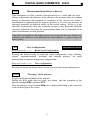
1
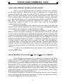
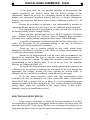
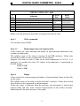
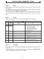
DIGITAL NANO-OHMMETER
32000 points autorange 1nΩ ÷ 320Ω
mod. 20024
USER MANUAL
PROFESSIONAL ME ASURING INSTRUMENTS
20024 MAN_GB.DOC
JUNE 2015
DIGITAL NANO-OHMMETER 20024
INDEX
INTRODUCTION
.
.
.
.
.
1
DESCRIPTION .
.
.
.
.
.
2
AUTO HOLD
.
.
.
.
.
3
DEFINITION BUTTONS AND INPUTS .
.
.
4
.
BUTTONS
.
.
.
.
.
4
.
.
.
.
.
.
13
AUXILIARY INFORMATIONS .
.
.
.
14
TECHNICAL SPECIFICATIONS
.
.
.
15
TIPS ON THE MEASUREMENT EXECUTION .
.
18
.
18
.
20
INPUTS
POTENTIAL OF CONTACT
.
.
.
USING THE METHOD OF BIPOLAR MEASURING.
MEASUREMENT ON RANGE 32µΩ
.
.
.
20
ELECTROMAGNETIC FIELS
.
.
.
21
.
22
.
22
.
22
CURRENT CABLES OF INSUFFUCIENT SECTION
SLOW OF MEASUREMENT
.
.
.
MEASUREMENT OF ELEMENTS HIGHLY INDUCTIVE
PROTECTION FROM OVERVOLTAGE AND OVERCURRENT
23
COMMUNICATION PORT
.
.
.
.
24
GENERALITY
.
.
.
.
.
24
READING DATA
.
.
.
.
.
24
WRITING SETUP .
.
.
.
.
28
DIGITAL NANO-OHMMETER 20024
DIGITAL NANO-OHMMETER 20024
INTRODUCTION
The digital nano-ohmmeter mod. 20024 is a instrument with
performance absolutely unique: although size and weight are extremely low,
provides resolutions and features never present together so far.
►
►
►
►
►
►
►
►
►
►
►
►
►
►
►
►
►
►
►
►
►
32000 measuring points / 5 measurements per second
8 ranges from 320 Ohm to 32 uOhm (from 10 mOhm to 1 nOhm of resolution)
current measurement can be selected
choice of automatic or manual range measurement
graphic display
bar graph
relative measure both absolute and percentage simultaneously of the main
measurement
temperature compensation of the measure from 0,0°C to 50,0°C
choice of the polarity of measurement
automatic measurement in both polarities indicating the average value
auto-zeringo the instrument
compensation of test leads
measurement hold
choice and display the magnitude of the filtering of the measure
backlight on/off
acoustic signaling of the correct selection
line and battery standard operation
indication of the state of battery charge
save/recall of configuration
reading data and setting via optocoupled USB
only two commands: one to read all the data and setup and one to write the
new setup
Accuracy, number of measuring points and resolution, as well as
reduced size and weight, make the instrument certainly unique and suitable for
use both in the laboratory as in the field. Indeed the presence of internal
rechargeable batteries shall release from the necessity of the mains voltage with
a autonomy that can reach a maximum of about 350 hours.
The main measure is also well represented with large characters 10mm
high that allow the reading to three meters away.
The instrument has no menu where you can select the options you want,
but only and simply the ability to slide four screens in which:
►
►
►
►
displays the main measure
displays the main measure and the relative and absolute percentage
is set the temperature compensation of the measurement
displays the measure compensated, the main measure and the temperature
1
DIGITAL NANO-OHMMETER 20024
DESCRIPTION
The instrument is mounted in a aluminum extruded anodized case. Of
limited weight, it has the handles to facilitate transportation and swivel feet in
order to better view of the display and accessibility to commands and test
sockets.
The graphic display 64x128 pixel is very large relative to the size of the
instrument, so as to facilitate the reading even from a distance and in low light.
Even the arrangement of the information (measuring primary and secondary,
settings and indications) has been designed to be easily readable and never create
confusion.
The entire instrument is managed by a 16-bit microprocessor, while the
technique of measurement is ratiometric four-wire, otherwise known as Kelvin
connection, the only one that allows you to get off at accuracies and resolutions
so thrusts.
The amplifier and converter are in a monolithic device so as to have an
equivalent input noise (with filter = 32) of only 100nVpp typical in a minute and
drifts lower than typical 300nVpp in 10 minutes.
On the front there are four bushings (A+, A-, V+, V-), two of which
provide for the measuring current and two for the detection of the voltage drop
across the resistor. The four-wire method makes it insensitive the measure from
resistance of the wires that carry the current and the various contact resistances
in the circuit nanoohmmeter - test leads - unknown resistance. The input signal is
then amplified and compared with the reference internal resistance: the result,
properly prepared and processed by a microprocessor, is shown on the LCD.
The low current used for the measurement reduced to the negligible
power dissipation for Joule effect, with the consequent very low alteration of the
measurement. For the same reason the fall of the maximum rated voltage of
32mV which avoids any semiconductor junctions in parallel to the unknown
resistance make the measurement invalid.
With the exception of range 32µΩ, you can choose between two
measurement currents. With the current "high" there is a resolution in 1µV
voltage, which drops to 0.1µV with the current "low". If the necessity is to have
a minimum dissipation on element under measurement, the choice is to use the
lower current, evidenced by written cur: before the value of the current, in the
lower part of the display. Otherwise it is recommended to use higher current,
shown with the CUR: before the value of the current, so as to minimize side
effects due to potential contact or drifts of the measuring amplifier. Important
notices in this regard are given in the section TIPS ON THE
MEASUREMENT EXECUTION.
2
DIGITAL NANO-OHMMETER 20024
Rx
ADC
uP
LCD
I
Rc
Block diagram of the nanoohmmeter
20024 and the four-wire measurement.
Fig. 1
CAUTION:
The presence of the sign "-" before the value of the
measure is only to indicate that they exchanged the
terminal voltage V- with V+: this does not result
dangerous to the instrument, but does not guarantee the
validity of the measure because the amplifier is optimized
for positive signs.
AUTO HOLD
The instrument has an Auto Hold function, ie the ability to "freeze" the
display when the test leads or the pliers are disconnected from the element under
test. In particular, this happens when you have the interruption of the circuit by
disconnecting at least one of the current terminal.
It is given to reporting on the status line at the bottom right of the screen
with the word AHld flashing.
CAUTION:
This function is automatically activated only when the
instrument is in Manual mode. This allows you to
maintain the auto-ranging
function for automatic
selection of the most suitable range to measure.
3
DIGITAL NANO-OHMMETER 20024
DEFINITION BUTTONS AND INPUTS
BUTTONS
The instrument has 12 buttons whose functions and modes of operation
are detailed below and summarized in a table below. Through them you can
directly select all the functionality of the instrument without resorting to menus
or keystrokes.
Four buttons are dual function and the selection of the function is based
on the time in which they are pressed: short if less than one second, or long if
greater than said time.
The two functions refer to the same mode. As an example consider the
BIP button. Pressing it briefly activates the bipolar measuring, while pressing for
a long time allows you to get out it.
A suitable acoustic alert if the function, or the pressed button, is active
or not. In certain conditions, in fact some buttons are disabled and pressing there
is a long beep. An example is the inability to perform an auto-zeroing procedure
during a bipolar measure. Pressing the A/Z button there is a long beep.
The following lists the buttons and their functions.
▲
Selection of the upper range
If the instrument is in Automatic mode go to Manual mode.
If the instrument is in Manual mode selects the range immediately above, unless
it has already been reached the range of 320Ω.
On the screen relative to the temperature compensation allows increasing this
parameter.
▼
Selection of the lower range
If the instrument is in Automatic mode go to Manual mode.
If the instrument is in Manual mode selects the range immediately below, unless
it has already been reached the range 32µΩ.
On the screen relative to the temperature compensation allows the decrease of
this parameter.
AUTO
Automatic/Manual mode
If the instrument is in Automatic mode is brought into Manual mode and vice
versa.
4
DIGITAL NANO-OHMMETER 20024
FUNC
Main measure
Multifunction button
Absolute and relative percentage
Setting the room temperature
Measurement with temperature compensation
The button passes successively displaying of
- main measure + bargraph
- main measure + bargraph + absolute and relative percentage
- setting the room temperature
- measurement with temperature compensation + main measure + room temperature
each time you press the button.
main measure + bargraph + absolute and relative percentage
Pressing the button when are displayed only
the main measure and the bargraph will
displayed also the relative measure expressed
as a percentage and absolute, both with sign.
The percentage value is calculated with the
formula
percentage = 100 * (actual_value – initial_value) / initial_value
where with the initial value and actual value are respectively indicated the value
read from the instrument at a time when you pressed the button and the last
acquired value, obtained from an average of readings equal to the value reported
by Flt.
The minimum and maximum values represented are respectively -100.0% to
+6550.0%. When the percentage value, in absolute terms, equals or exceeds
100% the resolution automatically changes from 0.01% to 0.1%.
In absolute representation you have the resolution of the range at that moment
on, while the value is expressed as
absolute = actuale_value – initial_value
5
DIGITAL NANO-OHMMETER 20024
setting the room temperature
By pressing the button you have the
disappearance of the main measure, of the bar
graphs and relative measures, while displaying
only the temperature compensation of the
resistance, denoted by Ta, ie ambient
temperature. This is because that temperature is
that at which the measurement is taken of the
unknown resistance.
In this screen the temperature is varied using the buttons ▲ and ▼ respectively
for increasing and decreasing the temperature value displayed on the right of the
screen, with a resolution of 0.1°C in a range between 0.0°C and 50.0°C. The new
value is automatically saved in non-volatile memory of the instrument when you
switch to the measure compensated.
measurement with temperature compensation + main measure + room
temperature
Pressing another once the button you have the
representation
of
the
compensated
measurement (at the top), while in the central
area is the actual measurement of the
resistance, indicated by Ra and performed at
room temperature, and the set room
temperature Ta.
The compensated measure refers to a standard
temperature of 20.0°C, according to CEI EN
60228:2005-10.
If you press the CFG button to save the configuration when you are on this
screen, recalling the saved configuration or switching on the instrument is called
this screen.
main measure + bargraph
Pressing the button disappears the screen with
the compensated measure and appears the
main measure and the bargraph.
If you press the CFG button to save the
configuration when you are on this screen,
recalling the saved configuration or switching
on the instrument is called this screen.
6
DIGITAL NANO-OHMMETER 20024
Interpretation of the operation of the bargraph
The bar graph under the main measure shows
graphically the value between 1040.0mΩ and
1049.9mΩ. In the picture the bar graph is set to a
value of 1040.0mΩ + 7.1mΩ (71 pixels).
The bar graph has a total of 100 "pixels" and
graphically displays the small variations of the
main measurement.
For example, if the primary measure is
264.15uΩ, the value to the left under the bar
graph would be 264.00uΩ and the bar graph would be 15 pixels long (0,15uΩ).
A/Z
Zeroing procedure
Button pressed < 1 sec
Multifunction button
Auto-zeroing
This multifunction button allows the auto-zeroing the instrument without the
need to disconnect the terminals of current or voltage and short circuit them.
This procedure, on instruments of high sensitivity such as this, if not done
properly could make it completely unreliable the measurement.
With the automatic procedure is also obtained compensation of the various
thermoelectric effects in the contact points between the terminal voltage and the
unknown resistance as well as all along the measuring cable up inside the
instrument for each contact of different metal materials. During execution of
auto-zeroing is obtained also the elimination of the drift of the measuring
amplifier.
Pressing the button for less than 1 second appear the words AUTOZERO
flashing and the bar timepiece until the completion of the procedure, the duration
of which is variable depending on the number of readings to be performed to
obtain the average, the value of which is set by FLT button.
Button pressed > 1 sec
Lead current compensation
The second function of this button is activated if this is pressed over a second
and allows to compensate the voltage drop on the current cables in a better way
than does the procedure of auto-zeroing. In fact, despite the high common mode
rejection of the input amplifier, when current cables have high voltage drop due
to the measurement currents of 1 ÷ 10A, or the section of these is insufficient or
they are too long, the amplifier is not able to fully compensate for the common
mode voltage variation that it comes to have between the normal operating
conditions (with the current circulating in the cables) and that of auto-zeroing
(when current is interrupted momentarily).
7
DIGITAL NANO-OHMMETER 20024
Although specifically designed for the compensation described above, and then
especially in the presence of measurement currents of 1A and 10A, this
possibility is active on all ranges since also allows zeroing the measurement if it
appears that, connected to the terminals as shown in Fig 2, the main measure is
not of zero value.
Fig. 2 Connection to be made
during the compensation of the voltage
drop on the current cables.
By its nature, the compensation is different for each range and depends on the
measuring current used. Compensation is therefore only valid for the range and
for the current measurement. For this reason the instrument saves the particular
compensation in the memory cell corresponding to that range and the current, so
as to recall it when they are selected again. The compensation is saved in nonvolatile memory at power down. Since the saved values are highly dependent on
the measurement conditions (length and cross-section of cable current, potential
thermoelectric and internal temperature of instrument, as well as elapsed time
from power on of the latter) it may happen that the next time you turn on the
instrument the compensation is no longer valid.
CUR
Selecting the Current Measurement
Toggles the current measuring low or high.
The nominal current measurement is indicated by the word cur: or CUR:
depending on whether low or high, respectively. For the range of 32µΩ, where
the current is only 10A, the writing depends on the last selection made.
BIP
Procedure of Bipolar Measure
Button pressed < 1 sec
Multifunction button
Activation bipolar measurement
Do not execute this command if the measure is overloaded.
8
DIGITAL NANO-OHMMETER 20024
If the instrument is performing the measurement with reverse current change it to
direct current then wait for a time dependent on the number of readings to be
performed to obtain the average, the value of which is set by pressing the FLT
button.
The bipolar measurement procedure consist to run the number of measurements
set by the FLT with the direct current and the same with the reverse current and
perform the average, then returning in direct current mode. During the procedure
appear the words BIPOLAR flashing and the bar timepiece. At the end of the
procedure the measurement is displayed and flashes BiPl at the bottom of the
screen. A further bipolar measurement can be started by pressing again the BIP
button.
Button pressed > 1 sec
Deactivation bipolar measurement
Pressing the button for longer than a second the instrument leaves the bipolar
measurement mode and disappears BiPl written at the bottom of the screen.
FLT
Selecting Filter
Each time the button is pressed you select a different filter value in the sequence
1-2-4-8-16-32-64-1-2-4 - ..... The number, which is also displayed at the bottom
of the screen after the word Flt:, indicates the number of acquisitions used to
calculate the average, which is the main measure represented.
This is particularly useful especially on the range of 32µΩ or when using the
measuring current low, where the instrument has a maximum sensitivity voltage.
The greater the number of measurements over which the average is performed
and more slowly responds the instrument. While maintaining a frequency of
update of the measurement on the display of 5 Hertz, has the advantage of better
stability of the representation.
It may happen that switching to a following filter value the main measure proves
unreliable temporarily, until the buffer of the measures is refilled.
BKL
Backlight
Turns on/off the backlight of the display.
In case of battery operation it is recommended to turn on the backlight only
when absolutely necessary since the power absorbed by the instrument,
excluding the measuring current, increases from about 120mW to 700mW,
reducing the operating time of the instrument considerably. The autonomy,
however, does not fall below 50 hours with the backlight actived and range
3200mΩ or higher.
9
POL
DIGITAL NANO-OHMMETER 20024
Measurement Mode Direct or Reverse
If the instrument is in Direct mode is brought into Reverse mode and vice versa.
Allows to determine the direction of the current in the element under test without
having to disconnect the terminals to reconnect in the reverse way when a
measurement is required with the opposite polarity or to assess the presence of
electrical potentials of different nature in the circuit voltage. In fact it is not
advisable to physically swap the terminals because it may determine different
electrical potentials, thwarting the measurement made just to determine or to
reduce the influence of such potential.
If possible you should use the higher current for execute the measure. In this way
minimizes the influence of the potential of contact thanks to a signal voltage ten
times greater.
CFG
Save Configuration
Button pressed < 1 sec
Multifunction button
Recall saved configuration
Pressing the button briefly is recall the saved configuration: range, filtering,
current, automatic/manual, backlight and function displays: the main
measurement or measure temperature compensated.
Button pressed > 1 sec
Save configuration
Pressing the button for longer than a second you save the current configuration.
HOLD
"Freezing" of the measure
Toggle on/off the hold mode of the measure.
During the Hold mode does not work any button, with the exception of the
buttons backlight BKL and filter FLT.
If the instrument is in hold mode Hold text is displayed flashing in the status line
at the bottom right of the screen.
10
DIGITAL NANO-OHMMETER 20024
In the table below are summarized the operation, the mode of activation
and the type of signaling in function of time for which a button is pressed.
Name
button
▲
Action
short/
long
short
Operation
Acoustic
warning
short/long
If in Autorange mode:
Exit from auto-range, remaining
in the selected range.
short
If in Manual mode:
If it has not reached the range of
320Ω passes to the upper range.
short
Do not execute the command if it
is on the range of 320Ω.
long
In the lower part of the screen appear the range
activates and the text "Man".
▼
short
If in Autorange mode:
Exit from auto-range, remaining
in the selected range.
short
If in Manual mode:
If it has not reached the range of
32µΩ passes to the lower range.
short
Do not execute the command if it
is on the range of 32µΩ.
long
In the lower part of the screen appear the range
activates and the text "Man".
AUTO short
If in Autorange mode:
Switch to Manual mode without
changing the range.
short
If in Manual mode:
Switch to Autorange mode
selecting the range that is suitable
for measurement.
short
In the lower part of the screen appear the range
activates and the text "Aut".
FUNC
short
Having a complex operation, refer to section relative to the FUNC
button to p. 5.
short
Measurement of Relative Absolute has the same
resolution as the main measure, while the measure
of Relative Percentage has a resolution of 0.01% up
to 99.99% and by 0.1% from 100.0% onwards.
A/Z
short
Perform a auto-zeroing the instrument.
short
long
If the measurement is in
Overload:
Do not execute the command
long
If measurement <1000 points:
Captures the value and
treats it as zero.
short
If measurement ≥1000 points:
Do not execute the command.
long
11
DIGITAL NANO-OHMMETER 20024
CUR
short
If the measuring current is
high and the range are from
320Ω to 320µΩ:
Switch to low current
measurement.
short
If the measuring current is
low and the range are from
320Ω to 320µΩ:
Switch to high current
measurement.
short
If the range is 32µΩ
(measuring current
fixed to 10A):
Do not execute the command.
long
The measuring current is indicated by the word
"cur:" or "CUR:" depending on whether low or high,
respectively. For the range of 32µΩ the word
depends on the last setting made.
BIP
short
If the measurement is in
Overload:
Do not execute the command.
long
If the measurement is valid:
short
Measurements are made using
direct and reversed polarity and is
represented the average.
The measure goes on hold and
you have the flashing of the word
BiPl on the bottom screen.
long
Exits from Bipolar measurement.
short
FLT
short
Each time the button is pressed you select a different filter value in
the sequence 1-2-4-8-16-32-64-1-2-4 - .....
short
BKL
short
Turns on/off the backlight of the display.
short
Given the high consumption of the backlight is
recommended, in case of battery operation, turning
it on only when absolutely necessary.
POL
short
Switch from direct to reverse polarity measurement and vice versa.
short
At the bottom of the screen appears "Dir" or "Inv".
CFG
short
Recall the saved configuration (range, filtering, current,
automatic/manual, measure compensated and backlight).
short
long
Save the current configuration of the instrument.
short
If the measurement is not in
Hold:
Block the measure and you have
the flashing of word Hold in
bottom of the screen.
Remain active only FLT, BKL
and CFG buttons.
short
If the measurement is in Hold:
Exits from block of the measure.
short
HOLD short
12
DIGITAL NANO-OHMMETER 20024
INPUTS
On the front panel there are only four test sockets, which are essential if
you want to measure resistances of low and very low value with the Kelvin
method.
A+ / A-
Current Terminals
These terminals provide the measuring current. With the current circuit open the
voltage present at the output is between 2V and 2.4V, depending on the state of
the battery and the presence or absence of the mains voltage.
V+ / V-
Voltage Terminals
Through these terminals is detected the voltage drop across the unknow resistor,
with a sensitivity that reaches 10nV on the range of 32µΩ.
GND
Ground Terminal
Located at the rear of the instrument is a standard bushing with hole 4mm in
diameter electrically connected to the housing. Can be used to improve the
rejection to environmental disturbance by connecting the instrument to the
ground.
Alternatively or in combination the same bushing can be used to connect a shield
of voltage cable, as shown in Fig 2 or Fig 3 on page 7 to page 18.
LINE
Power Socket
Located at the rear of the instrument is the power plug from the mains 230V ±
10% 48-66Hz and 5x20mm fuse holder with fuse 200mA delayed.
COM
Communication Port
Located at the rear of the instrument allows to communicate with a PC via an
optically isolated connection. You can read the data and setup of the instrument
and modify the setup.
13
DIGITAL NANO-OHMMETER 20024
AUXILIARY INFORMATIONS
In the five areas of the lower part of the
display the status line provides many auxiliary
information summarized in the table below.
Sector
Information
Indication
Note
Status of the
message
1
Range
320Ω
32Ω
3200mΩ
320mΩ
32mΩ
3200µΩ
320µΩ
32µΩ
Selected range
Permanent on
all ranges
2
Automatic /
Manual
Aut
Instrument in Autorange
mode
Permanent
Man
Instrument in Manual mode
Dir
The current flows from the
positive terminal
Inv
The current flows from the
negative terminal
Bipolar
BiPl
The instrument is
performing a bipolar
measure
Flashing
Hold
Hold
Instrument is in Hold mode
Flashing
AHld
Instrument is in Auto Hold
mode
Flashing
no indication
The instrument is not in
Hold or Auto Hold mode
and even in bipolar
measuring
no indication
Battery OK
image of a
battery with
charge level
gradually
decreasing
Battery charge level in
gradually decreasing
Permanent
image of empty
flashing battery
Fully discharged battery
Flashing
3
4
5
Direct / Reverse
Battery status
14
Permanent
DIGITAL NANO-OHMMETER 20024
TECHNICAL SPECIFICATIONS
Power supply
Power requirement
Battery
Battery autonomy
Representation
230V ±10% 48-66Hz fuse 200mA delayed
15VA
visual indication of charge status battery
view Tab. 2
on backlighted graphic display 64x128 pixels
62x44mm
32000
5 Hz
Points of measure
Display refresh rate
Range
32,000µΩ, 320,00µΩ, 3200,0µΩ, 32,000mΩ,
320,00mΩ, 3200,0mΩ, 32,000Ω, 320,00Ω
automatic / manual
Range selection
switch to range higher >31999 points
switch to range lower <3000 points
view Tab. 1 RESOLUTION AND
MEASURING CURRENT
±(0,05% + 0,001%/°C + 2 digit)
Automatic change of scale
Resolution and measuring current
Measurement accuracy (@ 20°C)
(range 320Ω ÷ 3200µΩ high current)
Measurement accuracy (@ 20°C)
(range 320Ω ÷ 3200µΩ low current)
Measurement accuracy (@ 20°C)
(range 320µΩ high current)
Measurement accuracy (@ 20°C)
(range 320µΩ low current)
Measurement accuracy (@ 20°C)
(range 32µΩ)
Noise
(referred to input from 0,01Hz to 0,1Hz)
Compensation current cable / Zeroing
±(0,06% + 0,001%/°C + 3 digit)
±(0,06% + 0,001%/°C + 3 digit)
±(0,07% + 0,001%/°C + 5 digit)
±(0,07% + 0,001%/°C + 5 digit)
200nVpp with filter = 16 (FLT = 16)
compensation of emf of voltage circuit and
the offset of the instrument up to ± 1000 digits
about 15 minutes within a tolerance of ±0,3 µV
0,0°C a 50,0°C in steps of 0,1°C
Heating time after the power up
Compensation range of the measure with the
room temperature (Ta)
Coefficient of temperature compensation
copper, according to standard
CEI EN 60228:2005-10
20,0°C (according to standard
CEI EN 60228:2005-10)
2,20 Vmax (battery operation)
2,40 Vmax (mains operation)
average on 1, 2, 4, 8, 16, 32, 64 measures
35 Henry / 150 ohm
0 ÷ 50 °C
-20 ÷ 60 °C
4770 gr. approximately
243x89x285mm (W x H x D)
Temperature at which the measurement is
reported
Open circuit voltage (A+) - (A-)
(current circuit open)
Filter
Maximum inductive value
Working temperature
Storage temperature
Weight
Dimension
15
DIGITAL NANO-OHMMETER 20024
The table below shows the values of resolution, measuring current and maximum
power dissipated by the unknown resistance depending on the selected full scale.
RESOLUTION AND MEASURING CURRENT
Range
Resolution
Resolution
(voltage)
Voltage
of f.s.
Current
(resistance)
(low/high)
Maximum
power
32µ Ω
1nΩ (10-9 Ω)
10nV
320µV
10A
3,2mW
320µ Ω
10nΩ (10-8 Ω)
10/100nV
0,32/3,2mV
1/10A
320µW/32mW
3200µ Ω
100nΩ (10-7 Ω)
0,1/1µV
3,2/32mV
1/10A
3,2/320mW
32mΩ
1µ Ω (10-6 Ω)
0,1/1µV
3,2/32mV
0,1/1A
0,32/32 mW
320mΩ
10µ Ω (10-5 Ω)
0,1/1µV
3,2/32mV
10/100mA
32µW/3,2mW
3200mΩ
100µ Ω (10-4 Ω)
0,1/1µV
3,2/32mV
1/10mA
3,2/320µW
32Ω
1mΩ (10-3 Ω)
0,1/1µV
3,2/32mV
0,1/1mA
0,32/32µW
320Ω
10mΩ (10-2 Ω)
0,1/1µV
3,2/32mV
10/100µA
32nW/3,2µW
Tab. 1 Summary table of the resolutions, sensitivity, measuring current and maximum
power dissipation of the unknown resistance as a function of the selected range.
To prevent which excessive heating inside of the instrument may cause
drifts in the measure, particularly so on the two lower ranges and when is used a
high measurement current, the battery charge current is about 1A when the
instrument is turned on and 2A current when it is off. Consequently, the full
charge when switched off involves approximately 20 hours of time, while if the
instrument is on and always working with measuring current, the charging time
can vary greatly depending on the selected range and the state of the backlight.
For measuring current of 1A and backlight on you have a slight discharge of the
battery which, if the measured current increases to 10A, is discharged about in
one hour.
The following is the graph of autonomy of the battery as a function of
the selected range and the switching on/off the backlight of the display.
16
DIGITAL NANO-OHMMETER 20024
Battery autonomy
with backlight, high current
32 uohm
without backlight, high current
320 uohm
ranges
3200 uohm
32 mohm
320 mohm
3200 mohm
32 ohm
320 ohm
open circuit
0
50
100
150
200
250
Hours
Tab. 2 Graph representing the autonomy of battery as a function
the selected range and status of the backlight.
17
300
350
DIGITAL NANO-OHMMETER 20024
TIPS ON THE MEASUREMENT EXECUTION
POTENTIALS OF CONTACT
After switching on the instrument, before taking any measurements, it
would be advisable to wait at least 10 minutes. This allows the necessary thermal
settling of the components of the nanoohmmeter.
In carrying out the measure is essential, in order to obtain the best
results, follow the connection diagram of the terminals of measurement shown in
Fig 3. In this way it is avoided that in the circuit voltage there are the contact
resistances of the current terminals, with a macroscopic alteration of the
measurement results.
With cables of Kelvin type this problem does not exist since the two
tweezers placed to end are connected in such a way as to avoid that the contact
resistances adversely affect the measurement.
Other sources of error may be the potential of contact that you have
when two different metal materials meet.
To minimize the influence of this physical phenomenon, it must try to
have the same type of contact between positive and negative terminal voltage
and the unknown resistance. This contemplates both the state of the surfaces
(polished, oxidized, dirty, etc..) that the material (other than material of a head of
the unknown resistance compared to another), as well as the different
temperature at which they can be the points of contact of the element under test.
If the type of contact to the positive terminal is similar to the negative
terminal, the two effects tend to cancel and at most remains a potential equal to
the difference of the two. If this effect remains constant over time is sufficient to
compensate him once
and for all, on the
contrary should be
periodically reset by
pressing A/Z button.
The change
that you mention is
mainly
due
to
variations
in
temperature between
the two points where
the voltage probes
touch the unknown
resistance: the only
way to get a stable
Fig. 3 Connection diagram for measuring four wires
and reliable measure
of a resistor of low value.
is to take every
18
DIGITAL NANO-OHMMETER 20024
precaution to ensure that immediately after an zeroing there are not fluctuations
in the temperature difference of the two points of contact.
All the above said phenomena are, in absolute value, certainly modest
(generally a few tenths of microvolts), but unfortunately they are more than
detectable by instruments of similar sensitivity. That's why it is essential to take
some basic and essential precautions to have a good quality of the measurement.
The main, but not the only ones, are:
•
Clean the surfaces of the terminals of the unknown resistance and
measuring cables from oil, water, oxides etc.
•
If the section of the current cables is less than or equal to 4mm2 these
must be of equal cross section, to avoid that a different heating by Joule
effect causes a drift of the measurement over time. In any case, it is
strongly recommended that you use cables of not less than 6mm2
when using the lower ranges of 3200µΩ, 320µΩ and 32µΩ.
•
Wait for the cooling of the object to be measured.
•
Avoid heating/cooling, even slightly and in whatever way, a terminal of
the resistor to be measured relative to each other.
•
Avoid concatenate the measurement cables with varying magnetic
fields that can cause a bad reading.
•
Always perform an auto-zeroing and possibly a compensation of test
lead to the first measure, and wait at least 10 minutes after the power
on before you use the instrument, if you want good accuracy and
stability of the measurement.
•
Always perform an auto-zeroing when you are on the range 3200µΩ,
320µΩ e 32µΩ or the test leads are connected to another resistance.
•
Do not change the measurement point after you have performed a
auto-zeroing.
Since the potential of contact may vary from point to point is essential,
to have the best results, do not move the points of measurement, even if these are
assumed to be equipotential: current flows and potential of contact different in
different points alter the measure . This is absolutely valid also if you wanted to
run an auto-zeroing: do not ever alter the electrical connection of the terminal
voltage between measurement and the auto-zeroing.
19
DIGITAL NANO-OHMMETER 20024
USING THE METHOD OF BIPOLAR MEASURING
When it is assumed the presence of potential of contact not symmetric
on the input terminals, which thus can not be eliminated by a simple autozeroing procedure, the solution is the use of the bipolar measurement mode.
Since for each representation there are more measurements with direct and
reverse current and a subsequent stop, this measurement system is inherently
very slow and therefore is to be used only when needed or for actually to verify
that there are asymmetric potentials comparing the result of a bipolar
measurement (which in theory is the correct one) with the measurement
available after a auto-zeroing.
Do not forget, however, that a difference of a few digits is possible and
normal. Is not expected, therefore, also in case of absence of potential of contact
or when these are symmetrical, a perfect identity of values.
Since the asymmetry of the potentials of contact is usually due to
different causes, their drift or noise may be different. This can lead to a variation
in time of the measurement more pronounced compared to the measurement with
symmetric potentials of contact, which by definition they cancel each other. If
there is an asymmetry in the potentials of contact, but you continue to use the
normal measurement mode (not bipolar), it should be noted that the correction
(zeroing) which is made may not be constant over time. Also considering a
asymmetric noise of amplitude and causes different, therefore more difficult
voidable mutually, we recommend using a filter of at least 16 when you run a
bipolar measuring: it helps to further reduce the variations in the measurement
results.
As can be activated/deactivated has already been explained in the
section on BIP button.
MEASUREMENT ON RANGE 32µΩ AND 320µΩ LOW CURRENT
Given that these two ranges have a sensitivity in voltage of only 10nV
(equal to about 1/1000 of the signal provided by a thermocouple for a change of
temperature of 1°C), its use must be entrusted to experienced personnel, capable
of evaluating the multiple phenomena that may incur in making unreliable the
measurement. It is necessary to be considered very carefully the temperature
gradients in both environment and on the resistance being measured. You must
choose appropriate connection points to the object under test by checking the
mechanical strength, avoid in any way air flows, partial lighting power (which
induce localized heating), magnetic fields, etc..
It is absolutely advisable to execute the measurement not less than 15 minutes
after switching on the instrument: this allows to achieve an appropriate balance
of thermal components of the instrument itself.
20
DIGITAL NANO-OHMMETER 20024
At this point there are two possible strategies of measurement that
exploit respectively the thermal inertia and the thermal settling of the
components. Indeed the passage of a measuring current of 10A determines a
heating and consequent unwanted thermal drift due to thermal phenomena,
however, that propagate and derive rather slowly, stabilizing at about 15 ÷ 20
minutes.
Having the possibility of perform a fast measurement is possible to
exploit the thermal inertia, so as not to give rise to a sufficient heat propagation.
If is required instead a measurement in time you will have to wait for
the thermal settling to have enough stability.
Please note that thermal drift can be as ±0,3µV (equal to ± 30 digits)
with a variation of about 0.5 to 1.5nV/sec, and it is normal to have variations,
including noise, settling thermal and potential for contact, 100 to 200 digits.
A possible arrangement, to minimize the drift and the settling time, is to
reduce the dissipation of the instrument making it run only on batteries,
obviously after having loaded well in advance.
Avoid any case to circulate cooling air that surely would create
differences and thermal variations on the cables of voltage measurement that
would cause many signal variations.
Should not be underestimated even the noise both environmental and
internal to the instrument. The latter is typically contained in approximately ±
200nV in a period of 1 minute. To reduce the variations in the short term it is
recommended to use a filtering high: 32 or 64. In any case, the minimum
filtering, on 320µΩ and 32µΩ, is 8.
As regards the electromagnetic noise could perform the measurement in
a Faraday cage or anechoic, connecting the instrument to the earth through the
appropriate rear bushing, bearing the closer together the tension cables, to
minimize the area, and the noise induced, within the coil of the signal.
If all this seems excessive, please note that measurements with
resolutions of 1nΩ are definitely very close measurable limits. Substantially
below the 0,1nΩ no longer able to go down. It is also recommended to put
adequate attention to the measurement with "low" current (allowed in all ranges
except 32µΩ) where the resolution of the output voltage is only 0,1µV,
definitely value to be considered low-level.
ELECTROMAGNETIC FIELDS
Other causes of instability or failure of the measurement or in zeroing
are attributable to the presence of magnetic fields can induce electrical noise can
move the level in DC of the signal. The best way to mitigate this influence is to
keep short the wires of the voltage and current and that are not wobbly or vibrate
21
DIGITAL NANO-OHMMETER 20024
even in proximity to static magnetic fields: this will cause the occurrence of
induced voltages of amplitude and frequency dependent on the movement.
CURRENT CABLES OF INSUFFICIENT SECTION
Another cause of error, even if in this case decidedly modest and found
only on the ranges from 3200µΩ, 320µΩ and 32µΩ, is due to the limited section
of the current leads. If in fact the section is less than 6 mm2 and the cable is
proportionally too long it has, between zeroing and measurement, a difference in
the voltage drop on the cable that the measuring amplifier is no longer able to
properly compensate, by introducing a error, with the cables supplied, usually
not more than 2 to 4 digits. The remedy is to use, on the lower range, cables of
elevated section and as short as possible.
If there is any cables that provide high falls and compensation is
necessary to reduce the error, see the instructions on page 7 relating to paragraph
Zeroing procedure.
SLOW OF MEASUREMENT
This is certainly not a cause of the error, but it may seem, sometimes,
that the instrument is too slow or even stop it: the reason is due to the value that
has been set in the filter. The higher this value, the longer the time that the
instrument takes to make a series of measurements on the unknown resistance.
MEASUREMENT OF ELEMENTS HIGHLY INDUCTIVE
The nanoohmmeter 20024 is able to measure the resistive component
also highly inductive elements such as transformers with a power of more than 1
MVA. To avoid damage or malfunction of the instrument is advisable to
connect, in parallel to the unknown resistance, a diode as shown in Fig 4, the
next page.
Such protection diode should however put only if actually there is a
need and in the presence of inductive loads, since on high range the reverse
current of the same diode can alter, although modestly, the measurement.
To protect the range from 320Ω to 320mΩ including is sufficient a
diode of the type 1N4004 or similar, able to withstand currents of 1A. For the
lower range (from 32mΩ to 32µΩ) is advisable to use a diode can withstand
higher currents.
Its function is mainly to protect the amperometric circuit. The voltage
circuit is protected against continuous differential voltages up to ± 35V and pulse
up to ± 100V for 1 second.
22
CAUTION:
DIGITAL NANO-OHMMETER 20024
The instrument is not able to bear, on the bushings of
measurement, the application of external voltages or
currents, especially if due to the direct connection with
the network line.
PROTECTION FROM OVERVOLTAGE AND OVERCURRENT
The instrument is provided with adequate protection against voltage
surges on voltage inputs, as specified in the technical specifications, but requires,
in the case of measurement of
predominantly
inductive
elements, an external protective
diode. Such a diode as shown in
the previous section, is fully
sufficient to protect the
generator current circuit. This
does not mean, however, that
the instrument is able to
withstand electrical stress such
as connection to motors or
transformers connected to its
power supply, especially if this
is the line network. The electric
power at stake in this case
would be well beyond those
Fig. 4 Connection diagram of the protection
tolerable by the protection
diode in parallel with an strongly inductive
element. Note the direction of insertion of the
circuitry, internal and external,
diode.
of nanoohmmeter and its
damage would be certain.
CAUTION:
It is important that the protective diode is connected in
parallel to inductive element and not between the
terminals of current or voltage, otherwise it is not able,
disconnecting current cables, to eliminate the strong
glitter that is created. The spark can also reach voltages of
thousands of volts and irreparably damage some
electronic circuits of the current generator.
23
DIGITAL NANO-OHMMETER 20024
COMMUNICATION PORT
GENERALITY
The nanoohmmeter 20024 is equipped as standard with a USB interface
optically isolated. Using the appropriate optional module, which looks similar to
a plug connector RS232 9 pin, you can connect the device to a PC to obtain the
following information:
►
►
►
►
►
main measure
relative measure
measure temperature compensated
room temperature for the compensation of the measurement
instrument status (range, filter, page view, current measurement, backlight,
etc.).
Also you can:
► set the room temperature for measure compensation
► change the setup of the instrument
All of this means of just two commands:
-
-
a read request with which the instrument provides all the information
available to it by sending a string of 13 bytes followed by a fourteenth
byte of checksum
a write command followed by a string of 5 bytes that represent the new
setup, to which is added a seventh byte of checksum
READING DATA
Is sent to a single request bytes of 00H value. The instrument complies
with 13 bytes of data followed by a checksum byte terminal, as shown in the
following table. The first 5 bytes are both read and write, or are bytes to be sent
to the instrument when requesting any changes to the setup. More details will be
given in section WRITING SETUP.
Some data in the form of bytes (range, filtering, and serial number),
others in the form of words as a set of two bytes (the main measurement, relative
measurement, compensated measurement and room temperature for
compensation), and still others as a set of flags with fields of one or two bits.
24
DIGITAL NANO-OHMMETER 20024
READ COMMAND = 00H
#
byte
1
2
3
4
5
6
7
8
9
10
11
12
13
14
Type of
data
Definition
upper byte of room temperature compensation
lower byte of room temperature compensation
range
filter
status1
status2
upper byte of main measure (absolute value)
lower byte of main measure (absolute value)
upper byte of relative value (absolute value)
lower byte of relative value (absolute value)
upper byte of temperature compensated measure
lower byte of temperature compensated measure
serial number instrument
checksum
Read /
Write
word
read and write
byte
byte
flag
flag
read and write
read and write
read and write
read
word
read
word
read
word
read
byte
byte
read
read
Below will be explained in detail how to interpret the data received.
byte 1-2
Room temperature of compensation
Represents the value of the temperature used to compensate the measurement
and is expressed without a decimal point or, equivalently, in tenths of a degree:
if the ambient temperature is set to of 27.4°C the value is equal to 274.
To obtain the value, perform this calculation:
temperature_value = byte1 * 256 + byte2
Is a value both read and write access.
byte 3
Range
This byte contains a code corresponding to the
selected range, as indicated in the table
opposite.
Is a variable both read and write.
25
RANGE
Code
Range
0
1
2
3
4
5
6
7
32µΩ
320µΩ
3200µΩ
32mΩ
320mΩ
3200mΩ
32Ω
320Ω
DIGITAL NANO-OHMMETER 20024
byte 4
Filter
This byte contains a code corresponding to the
selected filter, as indicated in the table
opposite.
Is a variable both read and write.
byte 5
FILTER
Code
Filter
0
1
2
3
4
5
6
1
2
4
8
16
32
64
Status1
This byte is a set of seven fields where is summarized the state of the instrument.
Is a variable both read and write.
Status1
0
1
Binary
weight
1
2
2
-
Measuring current
3
-
Backlight display
4
-
Measurement direct/reverse
5
-
Select range manual/automatic
6
-
Measurement active/in hold
7
-
Measurement active/in zeroing
# bit
Meaning
Value
Measure represented
26
0 = main measure + bargraph
1 = main measure + bargraph + absolute
and relative percentage
2 = setting room temperature
3 = measurement with temperature
compensation + main measure +
room temperature
0 = low current
1 = high current
0 = off
1 = on
0 = measured by direct current
1 = measured by reverse current
0 = manual
1 = automatic
0 = active
1 = in hold
0 = active
1 = in zeroing
DIGITAL NANO-OHMMETER 20024
byte 6
Status2
This byte is a set of 6 fields which complement the state of the instrument.
Is a read-only variable.
Status2
0
1
Binary
weight
1
2
2
3
1
2
Overload measurement
4
-
Sign of the main measurement
5
-
Sign of the relative measurement
6
7
-
not used
not used
# bit
byte 7-8
Meaning
Value
Bipolar measurement
0 = measurement not bipolar
1 = bipolar measurement
2 = bipolar measurement in hold
3 = not used
0 = no overload
1 = positive overload
2 = negative overload
3 = not used
0 = positive polarity (+)
1 = negative polarity (-)
0 = positive polarity (+)
1 = negative polarity (-)
Main measure
Represents the absolute value of the main measure and is expressed without
commas or units. The correct representation is determined by considering the
selected range and bit 4 of State2.
If a hypothetical measure is 217,43 mΩ (range code = 4), the value contained in
the two bytes considered is of 21743.
To obtain the value, perform this calculation:
main_measure_value = byte7 * 256 + byte8 (absolute value)
Is a read-only variable.
byte 9-10
Relative measure
Represents the absolute value of the relative measure and is expressed without
commas or units. The correct representation is determined by considering the
selected range and bit 5 di Stato2.
If a hypothetical measure is -1,09µΩ (range code = 1), the value contained in the
two bytes considered is of 109.
To obtain the value, perform this calculation:
relative_measure_value = byte9 * 256 + byte10 (absolute value)
Is a read-only variable.
27
byte 11-12
DIGITAL NANO-OHMMETER 20024
Room temperature of compensation
Represents the value of the room temperature used to compensate the
measurement and is expressed without comma or units of measure. The correct
representation is determined by considering the selected range and bit 4 of
State2.
If a hypothetical measurement is 1698,2µΩ (range code = 2), the value contained
in the two bytes considered is of 16982.
To obtain the value, perform this calculation:
temperature_compensated_measure_value = byte11 * 256 + byte12 (absolute value)
Is a read-only variable.
byte 13
Serial number
Is the instrument serial number.
Is a read-only variable.
byte 14
Checksum
Is the algebrical sum of thirteen bytes of data, truncated to the lower byte.
If hypothetically the sum of the byte corresponds to 07A2H (07A2 value in
hexadecimal notation) this byte is A2H.
Is a read-only variable.
WRITING SETUP
The whole setup of the instrument is written at one time by sending the
command byte 08H, following it by the same first five bytes received while
reading, amended as necessary to reflect the new desired setup.
It is reiterated that, regardless of how many and which bytes have been
modified, is absolutely indispensable send all five bytes represented in the table
below after the command byte 08H adding, as the seventh and last byte, the
checksum byte.
You should definitely consider when you want to change the setup, first
perform a read, so you have the updated position at the last moment of the state
and of the setup of the instrument.
28
DIGITAL NANO-OHMMETER 20024
WRITE COMMAND = 08H
#
byte
1
2
3
4
5
6
7
Type of
data
Definition
08H (command code for writing)
upper byte of room temperature compensation
lower byte of room temperature compensation
range
filter
state1
checksum
Read /
Write
byte
write
word
read and write
byte
byte
flag
byte
read and write
read and write
read and write
write
Below you will specify in detail how to interpret the data to send.
byte 1
Write command
Is a constant value of 08H..
byte 2-3
Room temperature of compensation
It has exactly the same meaning and modes of representation indicated in the
section on reading data.
The validity range of the value is between 0 and 500, inclusive. Values that
exceed these limits are not considered by the instrument.
Suppose you want to send a value to an room temperature of 31.2°C, it is
necessary to consider the value 312 which, in hexadecimal, is represented as
0138H, namely:
byte2 = 01H
byte3 = 38H
byte 4
Range
It has exactly the same meaning and modes of representation shown in the table
on the range.
The validity range of the value is between 0 and 7, inclusive. Values that exceed
these limits are not considered by the instrument.
If the new range is different from the previous, the instrument is forced into
manual mode and exits from eventual representation of the relative measure,
displaying only the main measure + bar graph.
29
DIGITAL NANO-OHMMETER 20024
byte 5
Filter
It has exactly the same meaning and modes of representation shown in the table
for the filter.
The validity range of the value is between 0 and 6, inclusive. Values that exceed
these limits are not considered by the instrument.
On two lower range (320µΩ and 32µΩ) any codes of filter less than 3 are forced
to 3, to ensure that an adequate filtering of measurements in the presence of
noise.
byte 6
State1
Being a set of flags each bit can be changed independently of any other.
State1
0
1
Binary
weight
1
2
2
-
Measuring current
3
-
Backlight display
4
-
Measurement direct/reverse
5
-
Select range manual/automatic
6
-
Measurement active/in hold
7
-
Measurement active/in zeroing
# bit
byte 7
Meaning
Value
Measure represented
0 = main measure + bargraph
1 = main measure + bargraph + absolute
and relative percentage
2 = setting room temperature
3 = measurement with temperature
compensation + main measure +
room temperature
0 = low current
1 = high current
0 = off
1 = on
0 = measured by direct current
1 = measured by reverse current
0 = manual
1 = automatic
0 = no request
1 = are asked to hold the measure
0 = no request
1 = asked the zeroing of the instrument
Checksum
Is the sum of the six bytes of data (including command byte), truncated to the
lower byte.
If hypothetically the sum of the previous byte corresponds to 02FBH (02FB
value in hexadecimal notation) this byte is FBH.
30
31
32
TEST CERTIFICATE
INSTRUMENT MODEL
.
.
.
SERIAL NUMBER INSTRUMENT
.
.
.
_______________________
BATTERY
.
.
.
.
.
USB PORT
.
.
TEMPERATURE of CALIBRATION
RANGE
RESISTANCE OF
REFERENCE
.
20024
.
OK
OK
.
.
.
.
.
.
.
_______________
MEASURED VALUE
320Ω
PRECISION
DECLARED
(high/low current)
0,5 ‰ / 0,6 ‰
RESULT
OK
32Ω
0,5 ‰ / 0,6 ‰
OK
3200mΩ
0,5 ‰ / 0,6 ‰
OK
320mΩ
0,5 ‰ / 0,6 ‰
OK
32mΩ
0,5 ‰ / 0,6 ‰
OK
3200µΩ
0,5 ‰ / 0,6 ‰
OK
320µΩ
0,6 ‰ / 0,7 ‰
OK
0,7 ‰
OK
32µΩ
TEST NOISE
.
.
.
.
.
OK
TEST EMC
.
.
.
.
.
.
OK
TEST BURN-IN
.
.
.
.
.
.
OK
.
.
.
.
OK
MANUAL, CABLES, SOFTWARE
This is to certify that the instrument conforms to the technical specifications relating thereto, as
stated in the technical specifications.
Date
The Verifier
__________
_______________
The Operator
_______________
____________________
DECLARATION OF CONFORMITY _______________
The company PEDRANTI ELIO, Via Cesare Battisti 33/B, Cardano al Campo - Varese, Italia,
declare under our sole responsibility that the instrument 20024, to which this declaration relates, is in
conformity with the rules laid down in directive CEE89/336.
.
Cardano al Campo, 07/07/08
33
Pedranti Elio
.