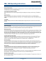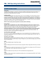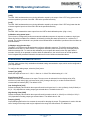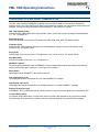
1
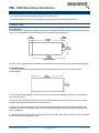
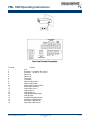
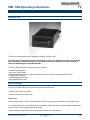
PML 1000 Operating Instructions
DESCRIPTION
This Set-up Guide describes how to install and configure your PML 1000.
This PML 1000 is marked with the international hazard symbol. It is important to read this Set-up Guide
before installing or commissioning your panel meter as it contains important information relating to
safety and Electromagnetic Compatibility EMC.
The PML 1000s provide the following features as standard:
• Scaleable Analog Output
• Dual Logic / Status inputs
• Optional RS485 Serial Communications interface with three protocols including MODBUS™ RTU
• 5 digit bright LED display
• Programmable function keys
• High Speed Analog output
INSTALLATION
To install your PML 1000 you will need to carry out the following steps:
• Install the PML 1000 into a panel.
• Make connections to the PML 1000.
Please note:
• Ensure that the power to PML 1000 is switched off before carrying out any installation or maintenance work.
• It is recommended that all connections to the terminals are made using ferrules to afford greater reliability and
to prevent short circuits between adjacent terminals.
• Avoid installing the PML 1000 close to switch gear, contactors or motor starters.
APP-01025, Rev A
PML 1000 Operating Instructions
www.meas-spec.com
1/18
1109
PML 1000 Operating Instructions
• Do not place signal and power supply wiring in the same wire way.
• Use shielded cables or wires for all signal/sensor leads with shield grounded at one point only.
CONNECTIONS
Panel Mounting
Ensure that there is sufficient space behind the panel for the depth of the PML 1000, allowing for safe routing of
cables. The diagram below shows a side view of the meter showing its dimensions.
The PML 1000 is supplied with an installation kit consisting of two mounting clamps and a panel-sealing gasket.
To install the meter:
1. Make panel cutout with dimensions as shown below. Panel thickness from l.5mm to 9.5mm can be
accommodated.
2. Fit the rubber seal by slipping it over the unit from the rear of the box pushing it forwards until it sits behind
the front lip of the unit.
3. Insert the PML 1000 into the panel from the front, pushing it through as far as the front lip, ensuring correct
seating of the rubber seal between the panel and the unit.
4. Working from behind the panel take the two mounting brackets locate on to the case as shown below (note
orientation of keyhole slots relative to the meter case). With the brackets located, slide them backwards until
they lock into place.
5. Tighten the screws until they bite into the panel securing the PML 1000 in place. Take care not to over tighten
the screws as this may damage the case.
APP-01025, Rev A
PML 1000 Operating Instructions
www.meas-spec.com
2/18
1109
PML 1000 Operating Instructions
Terminal
1
2
3
4
5
6
7
8
9
10
11
12
13
20
14
15
16
17
18
19
Function
N/C
Excitation + Yel./Red or Brn. (Pin F)
Excitation – Yel./Blk. or Yel. (Pin E)
Receive A
Receive B
Transmit A
Transmit B
Status (Logic) Input 2
Status (Logic) Input 1
Status Input Common (GND)
Power input Neutral (-)
Power Input Live (+)
Analog Output Analog Output +
High Speed Analog Output
CH2 (B) Input
Amplifier Gain Stage Output
Amplifier Gain Stage Input
Secondary 1 Red (Pin A)
Secondary 2 Blk. (Pin D)
APP-01025, Rev A
PML 1000 Operating Instructions
www.meas-spec.com
3/18
1109
PML 1000 Operating Instructions
CONNECTING THE COMMUNICATIONS INTERFACE
The diagrams below show the connections necessary to interface your PML 1000 to a PC RS485 / 422 port or
to an RS485 to RS232 Converter. It is recommended that screened twisted pair cable be used for all
applications requiring cable lengths greater than 3m. It is also recommended that a 1200 termination resistor is
added to across each pair of wires at the furthest point from the master device. The shield of the cable should
be connected to the frame ground or ground connection of the master device. The diagram below shows the
wiring required for both 4 wire full duplex and 2 wire half duplex installations.
POWERING THE PML 1000
The PML 1000 is designed to operate from an AC supply with voltages in the range 90 - 26SV AC SO/60Hz
mains supply. The maximum power consumption is 20VA when all outputs are fully loaded and the display has
all segments illuminated.
WARNING - The PML 1000 is designed for installation in an enclosure, which provides adequate
protection against electric shock. Access to power terminals should be restricted to authorized skilled
personnel only. Application of supply voltages higher than those for which the PML 1000 is intended
may compromise safety and cause permanent damage.
The diagram below shows how the PML 1000 should be connected to the mains supply. Isolation should be
provided by a double pole switch and a Time delay 1A fuse.
APP-01025, Rev A
PML 1000 Operating Instructions
www.meas-spec.com
4/18
1109
PML 1000 Operating Instructions
CONNECTING THE STATUS INPUTS
There are two status (logic) inputs on the PML 1000. These inputs can be used with voltage free contacts, such
as relays or switches. Open collector transistor outputs can also be used. The inputs are active low i.e. activated
by applying a short circuit between the status input and status common terminals. The diagrams below show
some typical applications. Note that these inputs are not isolated from the PML 1000s input circuit.
High Speed Analog Output
A buffered DC output of the demodulated LVDT input signal is provided by the PML 1000. The output level is
dependent upon the transducer excitation and the sensitivity of the LVDT. The output is not calibrated or
scaleable and it is recommended that it is used for diagnostic purposes only. Use terminals 20 (a-out +), and 13
(a-out -), to connect the High-Speed Analog output. This output is not isolated from the LVDT.
APP-01025, Rev A
PML 1000 Operating Instructions
www.meas-spec.com
5/18
1109
PML 1000 Operating Instructions
MENU MODE KEY FUNCTIONS/ OPERATOR MODE KEY FUNCTIONS
APP-01025, Rev A
PML 1000 Operating Instructions
www.meas-spec.com
6/18
1109
PML 1000 Operating Instructions
APP-01025, Rev A
PML 1000 Operating Instructions
www.meas-spec.com
7/18
1109
PML 1000 Operating Instructions
CONNECTING THE TRANSDUCER
The transducer should be connected to the PML 1000 as illustrated in the diagram below. The PML 1000 is
designed to operate with an LVDT in the Secondary to Primary Ratiometric Mode. Using this mode, the PML
1000 determines the measurement by taking into account both the primary and secondary voltages. The PML
1000 measures the differential output of the LVDT (SECA - SECB). The excitation voltage across the primary
coil is also measured. When using this measurement mode the measurements will automatically be
compensated for changes in the excitation voltage. See table on page five for additional LVDT connection
information.
MENU NAVIGATION
APP-01025, Rev A
PML 1000 Operating Instructions
www.meas-spec.com
8/18
1109
PML 1000 Operating Instructions
CONFIGURING THE DISPLAY
Decimal Point Position [dP]
Allow the position of the decimal point on the display to be set. The decimal point may be positioned to give 0,
1,2,3 or 4 digits after the decimal point i.e. 3 decimal places would be 99.000. The default is 1 decimal place.
Display Update Rate [rAtE]
This allows the update rate of the display to be set from every 0.1 seconds to 0.5 seconds. The options are 2, 4
or 10Hz, the default setting is 2Hz.
APP-01025, Rev A
PML 1000 Operating Instructions
www.meas-spec.com
9/18
1109
PML 1000 Operating Instructions
Display Filtering [Filt]
This parameter is used to set up filtering of displayed values. The time constant of the filter entered in seconds.
The default value is zero (no display filtering).
Least Significant Digit Zero [LSd0]
When this parameter is set to ON the right hand digit only displays zero during normal running. The default is
OFF.
Brilliance [briL]
Allows the brightness of the display to be adjusted to match other PML 1000s or to suit ambient lighting
conditions. The brightness may be set in the range 1 to 4. The default setting is 4 which is the highest intensity
setting.
Test [tESt]
Performs a display test which illuminates all display digits and segments (8.8.8.8.8.) when the enter button is
pressed.
CONFIGURING THE INPUT FOR YOUR LVDT
Introduction [inPt]
Before any calibration or scaling operations are performed some operating parameters related to the use of the
particular LVDT need to be set. These parameters are all set up from the input menu.
Setting Input Gain
There are two methods of determining the gain used by the PML 1000 for measurements and calibration. Firstly
the gain can be determined automatically at the time of calibration by the PML 1000. Set the auto option from
the input menu to ON. Alternatively, the sensitivity and stroke of your LVDT can be entered from the menu. This
data will normally be supplied with your LVDT. The sensitivity of the LVDT is normally quoted in mV/V/mm and
is entered in this form. The stroke is set in mm and is the -measurement range of the LVDT.
Automatic Gain Selection [AUto]
Allows the PML 1000 to set its gain automatically by determining the sensitivity of the attached LVDT during
calibration. A more detailed explanation of how this works can be found in Appendix A on Calibration. The
options are Automatic Gain Selection Enabled (On), the default state, or disabled (OFF).
Sensitivity [SEn]
This value is entered to allow the gain of the measurement input of the PML 1000 to be determined from the
specified sensitivity of the LVDT. Details of the sensitivity of your LVDT should be in the documentation supplied
by the manufacturer. The sensitivity is entered directly as a value in mV/V/mm The default sensitivity is 10.0
(mVlVlmm). This menu option is not accessible when Automatic Gain selection is enabled (On).
Stroke [Stro]
This allows the stroke of the LVDT to be entered as a value directly in mm This is used by the PML 1000 in
conjunction with the LVDT sensitivity to determine the appropriate gain setting. This menu option is not
accessible when Automatic Gain Selection is enabled. The default stroke setting is 100.Omm.
Excitation Voltage [Uout]
Select the correct output voltage for excitation for the LVDT. The nominal voltage will be specified in the LVDT
documentation. There are two options 3V AC and IV AC (rms.), the default setting is 3V.
Excitation Frequency [H2]
Set the excitation frequency closest to that specified in the LVDT documentation. The options are 2.5 kHz or 10
kHz. The default is 2.5 kHz.
APP-01025, Rev A
PML 1000 Operating Instructions
www.meas-spec.com
10/18
1109
PML 1000 Operating Instructions
CALIBRATION AND SCALING
Introduction
Your PML 1000 is designed to operate with a wide range of different LVDT types and in most commonly used
measurement modes. Before your LVDT can be used it must first be calibrated to the PML 1000. This is
performed very easily with the FAST CAL facility.
Calibration [CAL]
From the main Configuration menu select the CAL menu. The unit will display L-iP. Set the LVDT to its zero or
null position and press Enter. The unit will now calibrate to the zero input position of the LVDT. While this is in
progress, the unit will display Wait (VAIT). Once the zero (low) position has be calibrated the unit will display HIP. Set the LVDT to its maximum displacement position (normally full scale), and press enter. The unit will now
calibrate for this position. Wait will be displayed while this operation is in progress. At the end of the calibration
process the unit will return to the main menu and display CAL.
NOTE: For best results power the system for 30 minutes before calibrating.
Scaling (SCLE)
The PML 1000 is now calibrated to your LVDT. The default scaling is set to 100.0 units. To allow the unit to
display the correct displacement for your LVDT the low and high display values need to be defined. To set the
display scaling use the scaling menu, SCLE, and set the low display LDSP to the minimum displacement
calibration point value, (usually zero), and set the high display value to correspond to the maximum
displacement calibration point value, (usually full scale). Having defined the display scaling the PML 1000 will
now display displacement in the correct units of measurement and will be calibrated to the attached LVDT. In
some cases, it may be necessary to adjust the number of decimal places to give the best resolution. The
decimal point position may be changed from the display menu.
Low (Zero) Display Value [LdSP]
This is the 0% or minimum displacement display value, which corresponds to the Low calibration point (L-iP).
This value is entered directly but may be changed to any value within the display range of the PML 1000. The
default value is set to 0.0.
High Display Value [HdSP]
This is the 100% or maximum (span) displacement display value, which corresponds to the HiGH calibration
point (H-iP). This value is entered directly but may be changed to any value within the display range of the PML
1000. The default 100.0.
[CAL]
Main menu Calibration option. Press Enter to select.
[L¬P]
Unit is now waiting for the LVDT to be set to its zero (null) position. When ready press the Enter key to continue.
[VAit]
The Indicator will now measure the output from the LVDT. The indicator is now waiting for the LVDT to be set to
its full-scale position. When ready press the Enter key to continue.
[H¬P]
Unit will now measure the output from your LVDT and will determine the appropriate Gain.
[CAL]
Calibration is finished and has been completed successfully with no errors detected by the PML 1000. The PML
1000 returns to the menu.
APP-01025, Rev A
PML 1000 Operating Instructions
www.meas-spec.com
11/18
1109
PML 1000 Operating Instructions
[oUEr]
The PML 1000 has detected an error during calibration caused by the output of the LVDT being greater than the
maximum positive input level of the PML 1000 at the specified sensitivity.
[undr]
The PML 1000 has detected an error during calibration caused by the output of the LVDT being lower than the
minimum negative input level of the PML 1000 at the specified sensitivity.
[H=L]
The PML 1000 measured the same output from the LVDT at both calibration points. (High = Low).
Calibration using status input 1
The unit can be configured to perform an automatic calibration sequence in response to a status or logic input.
When this facility is enabled, the calibration is initiated by holding the status input active for a minimum of 1
second. The sequence followed is very similar to that followed when a calibration is performed from the Menu as
described above.
Calibration using function keys
The NEXT or STAR keys can be assigned to perform a calibration sequence. This facility can be enabled or
disabled from the KEY1 or KEY2 menus. To instigate a calibration press the function key, the display should
flash the message CAL. To continue with calibration you must press the same function key again within 5
seconds. If the key is not pressed to confirm within the allowed time, the unit will revert to normal operation.
Once instigated the procedure followed is the same as for menu initiation as described above.
CONFIGURING THE ANALOG OUTPUT
The PML 1000 provides a fully scaleable and isolated analog retransmission output, which can be configured to
your requirements.
To configure the analog output, select the [Aout] menu.
Output Type [tyPE]
Allows the output to be set to 0 –-10V, 0 - 20mA or 4 - 20mA. The default setting is 0 - 10V
Signal Source [SorC]
Defines the source of the values to be output. The source can be selected from the display value (inPt),
maximum or peak value (High), minimum value (LoW), Average value (Av) or a value received from the
communications interlace (SEr). The default is inPt.
Low Scaling Point [LoU]
Defines the display value at which the output will reach its minimum level i.e. 4mA (4-20mA), 0mA (O-20mA) or
0V (0 - 10V) dependant on analog output type selected above. The default value is 0.
High Scaling Point [Hi9H]
Defines the display value at which the output will reach its maximum level i.e. 20mA (0 or 4-20mA) or 10V (0 –
10V) dependant on analog output type selected above. The default value is 100.
Damping [dAnP]
Output damping defines the time constant in seconds for damping the output. This parameter is used to limit the
rate of change of the output and may be adjusted in the range 0 to 999 seconds. The default is 0.
APP-01025, Rev A
PML 1000 Operating Instructions
www.meas-spec.com
12/18
1109
PML 1000 Operating Instructions
CONFIGURING OPTIONAL SERIAL COMMUNICATION
The PML 1000 provides a RS48S/422 compatible communications interface. The interface is designed to
operate in both 2 and 4 wire (half and full duplex) communications systems. The unit supports three protocols as
standard, a simple text based command set plus MODBUS™ ASCII and RTU. (J-BUS).
PML 1000 Address [Addr]
Defines the PML 1000 address when using the PML 1000 in a multi-drop system, the range of valid addresses
is 1 - 247. The default is 1.
Baud Rate [bAud]
Allows the baud rate to be selected. The options are 1200, 2400, 4800, 9600. The default is 9600.
Protection [Prot]
Allows the PML 1000 parameter settings to be protected against change from the serial interface (write
protection ON). The default is OFF.
Parity [PrtY]
Defines parity for all communications. The options are even, odd or no parity. The default is Even.
Stop Bits [StoP]
Defines the number of stop bits, 1 or 2. The default is 1.
MODBUS™ Options
The following three parameters are for MODBUS™ communications protocols for data scaling and resolution.
Values returned from option locations i.e. Input Type, are not scaled.
Span [SPAn]
Span range used for MODBUS™ data scaling resolution.
Low Scaling Value [L¬P]
The display value which corresponds to 0 in a scaled MODBUS™ message.
High Scaling Value [H¬P]
The display value which corresponds to the SPAN (maximum) in a scaled MODBUS™ message.
Remote Terminal Unit [rtu]
If MODBUS™ RTU (sometimes known as J-BUS) protocol is required select this option ON. The default is OFF.
Transmit Delay [dELY]
Pre transmit delay adds a delay, in milliseconds, before the PML 1000 responds to any received commands.
This allows the unit to operate more reliably in two wire multidrop systems using older SCADA packages.
APP-01025, Rev A
PML 1000 Operating Instructions
www.meas-spec.com
13/18
1109
PML 1000 Operating Instructions
CONFIGURING STATUS INPUTS
The PML 1000 provides two status (logic) inputs, which can be assigned to perform one or more functions when
activated. With the exception of the Calibration function, which is started when there is a transition from inactive
to active state on the input, all other functions will be active only while the status input is active. The status
inputs are active low i.e. placing a short circuit across the input (from a switch or relay contact) will activate the
input. The following functions may be assigned to the status inputs 1 and 2:
Status 1
The default is OFF.
Displays [diSP]
Allows anyone of the following to be displayed while the status input is active: Lamp test, the average, low or
high values, or display hold. When the status input is inactive the normal measured value is displayed. The
default for this is NONE.
Reset [rSEt]
This resets the High (peak), Low (minimum) and Average values to the current measured value. The default for
this option is OFF.
Front Panel Keypad Disable [LoCR]
Disables the front panel keys, the default state is OFF.
Analog Output Hold [AHLd]
This allows the analog output to be held at a (Frozen) level. The default state is OFF.
Auto Fast Calibration [CAL]
This is used to initiate the automatic calibration process. The process is started when the status input is
activated. The default for this option is OFF.
Zeroing [2ErO]
This sets the measured and displayed values to Zero (0.000) permanently (or until the PML 1000 is defaulted),
removing any offset errors from the system. The default for this option is OFF.
Tare [tArE]
This tares the measured value subtracting a fixed amount from all subsequent measurements. The value
subtracted is the current value when the status input is activated (on a transition to the active state only), tare or
relative displacement will be displayed while the status input is active. The default is OFF.
Status Message Display [SdSP]
This enables or disables the display of messages related to the status input function. When ON messages are
displayed alternately with value being displayed i.e. if the unit is displaying the high value, then the high value is
displayed flashing with the message 'HiGH'. This indicates to the user that the current input value was not being
displayed. The default is OFF.
Status 2
Configured the same as Status 1.
APP-01025, Rev A
PML 1000 Operating Instructions
www.meas-spec.com
14/18
1109
PML 1000 Operating Instructions
CONFIGURING FUNCTION KEYS
There are two configurable function keys:
Function key 2
Function key 1
The following functions may be assigned either or both keys unless stated:
Displays [diSP]
Allows anyone of the following to be displayed while the Function key is pressed: Lamp test, the average, low or
high values, or display hold. When the key is released normal display is returned. The default is NONE (no
display function).
Reset [rSEt]
If ON, the function button will reset the High (Maximum), Low (minimum) and Average values to the current
measured value. The default is OFF.
Auto Fast Calibration [CAL]
If this parameter is ON then the function key 1 or 2 will initiate the automatic calibration process. When pressed
the display will flash the message 'CAL' the key must be pressed again while the display is flashing to perform
the function. The default state is OFF. This sets the measured and displayed values to Zero (0.000)
permanently (or until the PML 1000 is defaulted or calibrated), removing any offset errors from the system.
When assigned to a function key pressing the key once will cause the message 'ZEro' to be flashed. To perform
the ZERO the key must be pressed again to confirm the operation while the display is flashing (approximately 5
seconds). Once confirmed the ZERO will be performed immediately. The default state for this function is OFF.
Tare [tArE]
This tares the measured value subtracting a fixed amount from all subsequent measurements while the Tare
function is active. The value subtracted is the current value when the key is pressed. When the Tare function is
assigned to a function key pressing the key once will activate Tare (relative displacement) measurement,
pressing the key again while Tare is active, de-activates the Tare function.
SYSTEM OPTIONS
Password [PASS]
Password protection is enabled by entering any value between 1 and 99999. When this facility is enabled the
configuration menu cannot be accessed without first entering the correct password number. The default value is
0 (No Password).
Default [dFLt]
This allows the unit to reset back to its factory default settings. Select ON to default the PML 1000. This
parameter will automatically revert to OFF when the PML 1000 is defaulted.
Time-out [tout]
This defines the time in seconds that the unit will remain in configuration mode when there is no key activity. If
there are no key presses within the specified period, the unit will return to normal operation. The default time-out
is 90 seconds and is adjustable between 30 to 300 seconds.
Note: This facility is disabled during the Calibration sequence.
APP-01025, Rev A
PML 1000 Operating Instructions
www.meas-spec.com
15/18
1109
PML 1000 Operating Instructions
MESSAGES
Error Messages [Err1] [Err2] [Err3]
These messages indicate that a memory error has been detected in the PML 1000s internal memory area.
[AdEr]
This indicates that the PML 1000 has detected a fault in its measurement circuitry.
[uCAL]
The PML 1000 has detected a problem or error in its non-volatile memory resulting in a loss of calibration data.
Note: For any of the above error messages return the PML 1000 to the supplier.
[brA]
The PML 1000 has detected a problem with the sensor resulting in an open circuit input, this may be caused by
a break in one of the leads from the transducer or a fault in one of the transducer elements.
[oUEr]
The measured value is too large positively to be displayed, or is above the specified input range.
[undr]
The measured value is too low negatively to be displayed, or is below the specified minimum input for the
selected range.
PRODUCT SPECIFICATION
Supply
Operating Conditions
Ambient Temperature
90 - 265V AC SO/60Hz, 20VA max.
Humidity
- 10°C to 70°C
- 10°C to 50°C
10% to 95% RH non-condensing
Input
ADC
Input range
Resolution
Non Linearity
Temperature Drift
Stability
Input Impedance
Common mode rejection
Series mode rejection
High precision Sigma Delta
0.05V rms. - 5V rms.
18bit
< 0.02%
< 50ppm / °C
< 0.01 % FSO after 15 minutes
100kn
> 150dB
> 70dB @ 50/60Hz
Excitation
Voltage
Frequency
Temperature drift
3V AC rms. or IV AC nos. selectable
2.5 kHz or 10 kHz selectable
(amplitude) < 100ppm/°C (frequency) < 100ppm/°C
High Speed Analog OjP
Output
Response
±10V maximum
Output filter -3dB @ 125Hz
APP-01025, Rev A
PML 1000 Operating Instructions
Storage
Operating
www.meas-spec.com
16/18
1109
PML 1000 Operating Instructions
Analog Output
Ranges
Accuracy
Temperature drift
Output Ripple
Response
Resolution
Maximum output
Isolation
0-10V, 0-20mA or 4-20mA selectable
0.2% of span
< 100ppm/°C
< 10mV or50mA @ 30Hz
63% within 32mS
99% within lOOmS
0.05% of span, 5mV or 0.01mA
18V @ 25mA
500V
Communications Interface
Type
EIA RS485 (RS 422 Compatible)
Display Type
Range
0.56" High brightness 7 segment LED red (Optionally green)
-19999 to +99999
APPENDIX A CALIBRATION
Introduction
This appendix describes the steps necessary to calibrate your LVDT to your PML 1000 in more detail.
Initial Set-up
The LVDT should be connected to your PML 1000 as described earlier in this manual and the appropriate input
measurement mode selected from the input menu. You should also set up the correct excitation voltage and
frequency for your LVDT, as described in the documentation supplied with your LVDT. The PML 1000 uses
different amplification gains depending on the output of your LVDT. In order for the PML 1000 to set the correct
gain for your LVDT, you need to set the LVDT sensitivity and stroke values in the input menu. If you are unsure
of the characteristics of your LVDT then you should select the Automatic Gain selection option from the input
menu and set this to ON.
Null Position Locator
It is important that the LVDT operates around the midpoint of its stroke as this gives the best results by
minimizing any errors due to non-linearity. A feature of this PML 1000 is the ability to locate the midpoint of the
LVDTs measurement range (Null point). To do this select NULL from the main menu and a value will be
displayed (flashing). The nearer the value to zero the nearer the LVDT is to its null position. The LVDT should
be mounted so that the required measurement range is equally divided by the Null position.
Initial Calibration
To perform an initial calibration of the LVDT to the PML 1000 select the CAL option from the main menu. The
display will show the message L-iP (low input). Set the position of the LVDT to its minimum displacement
position (minimum stroke) and note the displacement i.e. 0mm. When the LVDT is set at its low calibration point
press the Enter key, the display will show Wait while the PML 1000 measures the output from the LVDT. This
takes a few seconds. When finished the display will show H-iP this indicates that the PML 1000 is ready to
calibrate the high point. Set the LVDT to its high calibration point maximum displacement position i.e. 200mm.
Press enter when ready to continue and the unit will display the message WAit while it is measuring the output
from the LVDT. At the end of the calibration sequence the PML 1000 will use the two measured output values
from the LVDT to calculate its own calibration constants which it will utilize in all future measurements. Note
these constants are all retained when power is removed from the PML 1000. When a calibration is performed
with the Automatic Gain selection enabled the PML 1000 will determine the optimum internal gain setting for all
future measurements from the output levels from the LVDT detected during calibration.
APP-01025, Rev A
PML 1000 Operating Instructions
www.meas-spec.com
17/18
1109
PML 1000 Operating Instructions
Scaling the Display
In order to display the displacement or other parameter in the correct units of measurement it is necessary to
first scale the PML 1000. To do this, select SCLE from the main configuration menu and enter the desired Low
and High display values. The low display value corresponds to the displacement at the Low input (calibration)
point i.e. 0 (mm). The high display value corresponds to the displacement at the high input (calibration) point i.e.
200 (mm).
Calibration
Subsequent routine calibrations of the LVDT to the PML 1000 can be performed either from within the menu's or
by assignment of either a status input or function key. The low and high display scaling values will be retained
throughout subsequent calibrations, all subsequent calibrations must be performed using the same points
otherwise the LDSP and HDSP values will need to be changed.
The calibration points used may be set anywhere in the display range of the PML 1000 i.e. -19999 to 99999.
The can read above and below the nominal calibration points although for best performance it is advisable to
calibrate at the extremes of the required measurement range.
ORDERING INFORMATION
NORTH AMERICA
EUROPE
Measurement Specialties
1000 Lucas Way
Hampton, VA 23666
United States
Tel: 1-800-745-8008
Fax: 1-757-766-4297
Sales: [email protected]
Measurement Specialties
(Europe), Ltd.
Hauert 13
44227 Dortmund
Germany
Tel: +49 (0) 231 9740 0
Fax: +49 231 9740 20
Sales: [email protected]
ASIA
Measurement Specialties
(China), Ltd.
No. 26 Langshan Road
Shenzhen High-Tech Park (North)
Nanshan District, Shenzhen 518107
China
Tel: +86 755 3330 5088
Fax: +86 755 3330 5099
Sales: [email protected]
The information in this sheet has been carefully reviewed and is believed to be accurate; however, no responsibility is assumed for
inaccuracies. Furthermore, this information does not convey to the purchaser of such devices any license under the patent rights to the
manufacturer. Measurement Specialties, Inc. reserves the right to make changes without further notice to any product herein. Measurement
Specialties, Inc. makes no warranty, representation or guarantee regarding the suitability of its product for any particular purpose, nor does
Measurement Specialties, Inc. assume any liability arising out of the application or use of any product or circuit and specifically disclaims
any and all liability, including without limitation consequential or incidental damages. Typical parameters can and do vary in different
applications. All operating parameters must be validated for each customer application by customer’s technical experts. Measurement
Specialties, Inc. does not convey any license under its patent rights nor the rights of others.
APP-01025, Rev A
PML 1000 Operating Instructions
www.meas-spec.com
18/18
1109