1
TECHNICAL SPECIFICATIONS
Output / Supply
- active sensor 0-10 V or 4-20 mA (alim. 24 Vac/Vdc ± 10%), 3-4 wires
- passive loop 4-20 mA (power supply 16/30 Vdc), 2 wires
- maximum load : 500 Ohms (4-20 mA)
- minimum load : 1 K Ohms (0-10 V)
Consumption
2 VA (0-10 V) or max. 22 mA (4-20 mA)
Electromagnetical compatibility
EN61326
Electrical connection
Screw terminal block for cables from 0.05 to 2.5 mm2 or from 30 to 14 AWG
Communication to PC
USB-mini DIN cable
Environment
Air and neutral gases
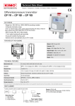
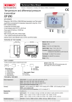
CONNECTIONS
Inside the front housing
Fixed back housing
Removable front face
LCC-S
connection
Solenoid valve
(only CP111)
Left DIP
switch Right DIP
switch
Power supply terminal
block
Output terminal
block
Autozero
Cable gland
Pressure connections
ELECTRICAL CONNECTIONS – as per NFC15-100 standard
This connection must be made by a qualified technician. To make the connection, the transmitter must not be energized.
To make a 3-wire connection, before powering up the
transmitter, please connect the output ground to the
input ground. See drawing below.
For CP111/112/113 – AO models and CP111/112/113 – AN
models with 0-10 V or 4-20 mA output – active, 4 wires :
VP GND IP
1
4
+
3
2
+
5
6
+
7
VP GND IP
1
2
6
- +
4 5
+
3
+
7
GND IP
4
wires
+
- +
4 5
3 wires
N
6
L
7
-
V
Regulator display or
PLC/BMS
passive type
or
+
Power supply
24 Vdc
-
+
A
+
- Power supply
V
24 Vdc
Regulator display or
PLC/BMS passive type
or
N L
6 7
or
Regulator display or
PLC/BMS passive type
-
+
A
Regulator display or PLC/BMS
N
4 wires
-
+
L
Power supply
24 Vac
class II
passive type
3 wires
or
L
N Power supply
24 Vac
class II