1
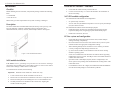
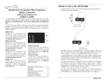
N-FX-xx-02(x)
USER’S GUIDE
N-FX-xx-02 (standard)
N-FX-xx-02(L) (low profile)
100Base-FX, Fast Ethernet Fiber NICs
Transition Networks’ N-FX series of fast
Ethernet NICs (Network Interface Cards)
provide a 100Base-FX fiber port to deliver
low-cost fiber optic connectivity to the desktop
in fiber-rich LAN environments. With both
standard and low profile form factors, driver
support for most operating systems, and PCI
2.2 plug-and-play capability, these fast Ethernet NICs can be installed in virtually
Part Number
Port One - Duplex Fiber-Optic 100Base-FX
N-FX-ST-02
N-FX-ST-02(L)
ST, 1300 nm multimode, 2 km (1.2 miles)*
N-FX-SC-02
N-FX-SC-02(L)
N-FX-LC-02
N-FX-LC-02(L)
SC, 1300 nm multimode, 2 km (1.2 miles)*
N-FX-MT-02
any
PC on the network.
N-FX-MT-02(L)
N-FX-SC5-02
N-FX-SC5-02(L)
N-FX-SC20-02
N-FX-SC20-02(L)
N-FX-SB201-02
N-FX-SB201-02(L)
N-FX-SB202-02
N-FX-SB202-02(L)
MT-RJ, 1300 nm multimode, 2 km (1.2 miles)*
LC, 1300 nm multimode, 2 km (1.2 miles)*
SC, 1310 nm single mode, 5 km (3.1miles)*
SC, 1310 nm single mode, 20 km (12.4 miles)*
SC, 1310 TX/1550nm RX single mode, single fiber 20 km
(12.4 miles)*
SC, 1550 TX/1310 nm RX single mode, single fiber 20 km
(12.4 miles)*
Optional accessories sold separately
Part Number
Description
BTR-NFX
Boot ROM chip supports BBS (Bios Boot specification) and
non-BSS compliant PCs.
*Typical maximum cable distance. Actual
distance is dependent upon the physical
characteristics of the network installation.
Installation . . . . . . . . . . . . . . . . . . .2
Cable Specifications . . . . . . . . . . .4
Technical Specifications . . . . . . . .5
Troubleshooting . . . . . . . . . . . . . . .6
Contact Us . . . . . . . . . . . . . . . . . . .7
N-FX Series Fast Ethernet NICs
Install the N-FX module -- continued
Installation
Checklist
5.
Ensure that the module is firmly seated in the slot.
Before installing the N-FX module, verify that the package contains the following
items:
6.
Use the screws from step “3” to secure the module to the workstation or
file server housing.
• N-FX module
N-FX PCI module configuration
• LAN driver CD
For motherboards with automatic PCI configuration:
Please notify your sales representative if any item is missing or damaged.
•
No specific setup is needed.
•
Description
The N-FX module has a bootable ROM socket (ROM chip sold separately). The
two LED indicators, LINK/ACT and FDX located on the bracket, show
network/board link, activities, collision, and full-duplex statuses. See Figure 1.
You can enter the system BIOS setup menu to view or specify the interrupt
(INT) line of the PCI slots.
For motherboards with bus master and interrupt jumpers:
•
Enable bus master operation in a selected PCI slot and select an INT
request line (IRQ) level, using the appropriate motherboard jumper.
•
Enable I/O on the N-FX, PCI slot.
PCI bus system and configuration
Figure 1: LEDs and Boot ROM Socket
N-FX module installation
CAUTION: Wear a grounding strap and observe electrostatic discharge
precautions when installing the N-FX module. Failure to observe this caution
could result in damage or failure of the N-FX module.
•
Ensure that the PCI machine supports master slots, and INT multiple
sharing and timing compatibility.
•
DO NOT install N-FX in PCI slave slots. Please refer to your PC system
manual and select the appropriate configuration settings.
•
When installing multiple N-FX modules in a server station, you should
correctly configure the IRQ settings of the PCI slot.
•
Up to four N-FX modules can be installed in a PCI file server running
NetWare operating system.
•
N-FX server modules share the same INT line with the driver supporting
multiple INT services at a time. The IRQ of each N-FX module should not
conflict with other boards.
•
Operation in full or half-duplex (default) mode is configured by LAN
driver options. The operating mode should match the working status of the
remote link device.
•
Use EMM386 version 4.49 or higher, and install both DOS and EMM386
from the same DOS package to avoid software problems.
To install the N-FX module, do the following:
Important: Install the N-FX module in a “master slot” only.
2
1.
Locate a master slot on the PC workstation or file server.
2.
Remove the cover from the PC workstation or file server—keep all screws.
3.
Remove and keep the screws holding the cover over the installation slot.
4.
Carefully slide the N-FX module into the “master slot,” aligning the
module with the slot guides.
Tech Support: 1-800-260-1312 International: 00-1-952-941-7600, 24 hours
[email protected] -- Click the “Transition Now” link for a live Web Chat.
3
N-FX Series Fast Ethernet NICs
Cable Specifications
Technical Specifications
For models N-FX-xx-02 and N-FX-xx-02(L)
Fiber cable
Bit error rate:
Single mode fiber (recommended):
Multimode fiber (recommended):
Multimode fiber (optional):
<10-9
9 µm
62.5/125 µm
100/140, 85/140, 50/125 µm
Standards:
Expansion bus standard:
Data rate
LED:
N-FX-ST-02(x), N-FX-SC-02(x), N-FX-LC-02(x), N-FX-MT-02(x)
Fiber optic transmitter power:
Fiber optic receiver sensitivity:
Link budget:
1300 nm multimode
min: -19.0 dBm max: -14.0 dBm
min: -31.0 dBm max: -17.0 dBm
12.0 dB
N-FX-SC5-02(x)
Fiber optic transmitter power:
Fiber optic receiver sensitivity:
Link budget:
1310 nm single mode
min: -19.0 dBm max: -14.0 dBm
min: -31.0 dBm max: -7.5 dBm
12.0 dB
N-FX-SC20-02(x)
Fiber optic transmitter power:
Fiber optic receiver sensitivity:
Link budget:
1310 nm single mode
min: -15.0 dBm max: -8.0 dBm
min: -31.0 dBm
max: 0.0 dBm
16.0 dB
N-FX-SB201-02(x)
1310 TX/1550 RX nm single mode
single stand
min: -14.0 dBm max: -8.0 dBm
min: -32.0 dBm
max: 0.0 dBm
18.0 dB
Fiber optic transmitter power:
Fiber optic receiver sensitivity:
Link budget:
N-FX-SB202-02(x)
Fiber optic transmitter power:
Fiber optic receiver sensitivity:
Link budget:
1550 TX/1310 RX nm single mode
single stand
min: -14.0 dBm max: -8.0 dBm
min: -32.0 dBm
max: 0.0 dBm
18.0 dB
The fiber optic transmitters on the device meet Class I Laser safety requirements
per IEC-825/CDRH standard and comply with 21CRF1040.10 and
21CRF1040.11.
Drivers:
Boot server support:
PCB dimensions:
Weight:
Power consumption:
MTBF
Opearting temp:
Storage temp:
Humidity:
Altitude:
Warranty:
IEEE 802.3
PCI 2.1, 2.2
100Mbps fiber media
LINK/ACT (on the bracket)
ON = communication link; FLASHING = activity
on link
FDX (full duplex link); ON = full duplex link
• Windows 95, 98, ME, 2000, 2003. XP, NT4.0
• NDIS 2, 3, 4, 5
• NetWare Server 3.12, 4.x, 5x, 6.x
• Netware DOS Client ODI
• MAC OS
• Linux x86, AMD64
• FreeBSD 3.2, 4.x, 5.x
• SOC Unixware 7.1, OpenUnix 8
• SCO Open Server 5.0.x
• Solaris 8, 9, 10
PXE, RPL, Netware NCP/IPX, DHCP, BootP
2.2”W x 4.8”D x 0.9”H
(55.9 mm x 121.9 mm x 23 mm)
3 oz. (91g) approximate
1.0A @ +5VDC
184,743 hours (Bellcore7 V5.0)
0°C to 50°C (32°F to 122°F)
-25°C to 85°C (-13°C to 185°F)
5% to 90%, non-condensing
0 to 10,000 feet
Lifetime
WARNING: Visible and invisible laser radiation when open: DO NOT stare into
the beam or view directly with optical instruments. Failure to observe this warning
could result in damage to your vision or blindness.
CAUTION: Use of controls, adjustments, or the performance of procedures other
than those specified herein may result in hazardous radiation exposure.
The information in this manual is subject to change without further notice.
4
Tech Support: 1-800-260-1312 International: 00-1-952-941-7600, 24 hours
[email protected] -- Click the “Transition Now” link for live Web chat.
5
N-FX Series Fast Ethernet NICs
Troubleshooting
Contact Us
Technical support
Diagnostics LEDs and Boot ROM
Technical support is available at [email protected]
LEDS
The LINK/ACT LED lights when a fiber cable or twisted pair cable connection
is good. It blinks to indicate activity.
The collision and full-duplex LED report board operating status.
Boot ROM
To add the remote boot feature to a workstation, insert the Boot ROM into the
ROM socket. See Figure 1 on page 2.
After power UP, the LINK/ACT LED should light; if not, check the following:
• US and Canada:
1-800-260-1312 (24 hours)
• International:
00-1-952-941-7600 (24 hours)
Transition now
Chat live via the Web with Transition Networks Technical Support. Log onto
www.transition.com and click the Transition Now link.
Web-based seminar
Transition networks provides seminars via live, web-based training. Log onto
www.transition.com and click the Learning Center link.
Email
1
Confirm that the N-FX module is properly inserted into the master slot.
2
Confirm that the PC is properly connected to a power source and with the
power source turned ON.
3
Check the fiber cable for proper connection.
Transition Networks
4
Contact Tech Support: 1-800-260-1312, Int’l: 00-1-952-941-7600 if those
steps fail to produce the desired result.
6475 City West Parkway
Note: To connect this device to a router, bridge, or switch, please refer to the
corresponding technical manual for the device.
Ask a question anytime by sending an email to our technical support staff:
[email protected]
Address
Minneapolis, MN 55344, U.S.A.
Telephone:
952-941-7600,
Toll free:
800-526-9267
Fax:
952-941-2322
Declaration of Conformity
Name of Mfg:
Transition Networks, 6475 City West Parkway,
Minneapolis, MN 55344 U.S.A.
Model:
N-FX-xx-02 and N-FX-xx-02(L) Network Interface Cards
Part Number:
N-FX-ST-02(x), N-FX-SC-02(x), N-FX-LC-02(x)
N-FX-MT-02(x), N-FX-SC5-02(x), N-FX-SC20-02(x),
N-FX-SB201-02(x), N-FX-SB202-02(x)
Regulation:
EMC Directive 89/336/EEC
Purpose:
To declare that the N-FX-xx-02 and N-FX-xx-02(L), to which
this declaration refers, is in conformity with the following
standards:
CISPR 22:1997+A1:2000; EN 55022:1998+A1:2000 Class A; FCC Part 15 Subpart B;
21CFR subpart J
I, the undersigned, hereby declare that the equipment specified above conforms to the above Directive(s)
and Standard(s).
Stephen Anderson, Vice-President of Engineering
6
June 30, 2005
Date
Tech Support: 1-800-260-1312 International: 00-1-952-941-7600, 24 hours
[email protected] -- Click the “Transition Now” link for live Web chat.
7
Compliance Information
CISPR22/EN55022 Class A, CE Mark, CISPR22/EN55022 Class A + EN55024, CE Mark
FCC regulations
This equipment has been tested and found to comply with the limits for a Class A digital device,
pursuant to part 15 of the FCC rules. These limits are designed to provide reasonable protection
against harmful interference when the equipment is operated in a commercial environment. This
equipment generates, uses, and can radiate radio frequency energy and, if not installed and used in
accordance with the instruction manual, may cause harmful interference to radio communications.
Operation of this equipment in a residential area is likely to cause harmful interference, in which
case the user will be required to correct the interference at the user's own expense.
Canadian regulations
This digital apparatus does not exceed the Class A limits for radio noise for digital apparatus set out
on the radio interference regulations of the Canadian Department of Communications.
Le présent appareil numérique n'émet pas de bruits radioélectriques dépassant les limites applicables
aux appareils numériques de la Class A prescrites dans le Règlement sur le brouillage
radioélectrique édicté par le ministère des Communications du Canada.
European regulations
Caution: This is a Class A product. In a domestic environment this product may cause radio
interference in which case the user may be required to take adequate measures.
Achtung! Dieses ist ein Gerät der Funkstörgrenzwertklasse A. In Wohnbereichen können bei
Betrieb dieses Gerätes Rundfunkstörungen auftreten. In diesem Fäll ist der Benutzer für
Gegenmaßnahmen verantwortlich.
Attention! Ceci est un produit de Classe A. Dans un environment domestique, ce produit risque de
créer des interférences radioélectriques, il appartiendra alors à l'utilsateur de prende les measures
spécifiques appropriées.
In accordance with European Union Directive 2002/96/EC of the European Parliament
and of the Council of 27 January 2003, Transition Networks will accept post usage
returns of this product for proper disposal. The contact information for this activity can be
found in the 'Contact Us' portion of this document.
CAUTION: RJ connectors are NOT INTENDED FOR CONNECTION TO THE
PUBLIC TELEPHONE NETWORK. Failure to observe this caution could result in
damage to the public telephone network.
Der Anschluss dieses Gerätes an ein öffentlickes Telekommunikationsnetz in den EGMitgliedstaaten verstösst gegen die jeweligen einzelstaatlichen Gesetze zur Anwendung der
Richtlinie 91/263/EWG zur Angleichung der Rechtsvorschriften der Mitgliedstaaten über
Telekommunikationsendeinrichtungen einschliesslich der gegenseitigen Anerkennung ihrer
Konformität.
Trademark notice
All registered trademarks and trademarks are the property of their respective owners.
Copyright restrictions
© 2004-2005 Transition Networks. All rights reserved. No part of this work may be reproduced or
used in any form or by any means—graphic, electronic or mechanical—without written permission
from Transition Networks
Printed in the U.S.A.
Manual Part Number and Rev.
33338.B