1
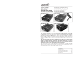
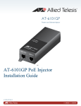
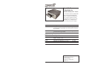
User’s Guide
CPSMC0200-22x
Dual-Slot PointSystem™ Chassis
The Transition Networks CPSMC020022x series dual-slot PointSystem™
chassis is designed for installation of
two selectable Transition Networks
PointSystem™ media converter slidein-modules. The redundant power
option provides the means to power the chassis from two independent power supplies.
Part Number
Description
CPSMC0200-221
Dual-Slot Point System chassis with two power supplies (one
grounded and one ungrounded). The chassis provides Last Gasp
trap generation.
CPSMC0200-226
Dual-Slot Point System chassis with two power supplies (one
grounded and one ungrounded).
Optional Accessories (sold separately)
Part Number
SPS-1872-SA
Description
Optional External Power Supply; 18-60VDC Stand-Alone
Output: 12.6VDC, 1.0 A
WMBP
WMBV
WMBD
Optional Wall Mount Bracket; Length: 5.0 in.
Optional Vertical Mount Bracket: 5.0 in.
Optional DIN Rail Mount Bracket: 5.0 in.
(127 mm)
(127 mm)
(127 mm)
Installation . . . . . . . . . . . . . . . . . .2
Technical Specifications . . . . . . . .4
Troubleshooting . . . . . . . . . . . . . .5
Compliance Information . . . . . . . .6
Contact Us . . . . . . . . . . . . . . . . . .7
CPSMC0200-22x
Installation
Installation -- Continued
Installing a slide-in-module
Power the chassis
CAUTION: DO NOT install Two (2) Point System media converter slide-in-modules
with a total power requirement exceeding 12 W (with an average of 6 W per slot).
Failure to observe this caution could result in data losses and media converter failure.
CAUTION:
CAUTION: Wear a grounding device and observe electrostatic discharge precautions
when installing the media converter slide-in-module into the chassis. Failure to
observe this caution could result in damage or failure of the media converter.
Note: If only installing one slide-in-module, ensure network standards compliance by
obtaining a custom faceplate (P/N CPSFP-200) from Transition Networks for
installation into the second, unused slot.
To install a slide-in-module into the dual-slot chassis:
1.
Refer to the user’s guide that comes with the slide-in-module to ensure that any
switches or jumpers on the slide-in-module circuit board are set correctly for the
site installation.
2.
Carefully align the slide-in-module with the chassis installation guides and slide
the module into the installation slot.
3.
Ensure that the slide-in-module is firmly seated inside the chassis.
4.
Push in and rotate the attached panel faster screw clockwise to secure the slide-inmodule to the chassis front.
5.
Repeat steps 1-4 for the second slide-in-module.
When using two power supplies to power the chassis, one must be a power supply with
an ungrounded secondary. Using two power supplies (with each secondary grounded
to protective earth ground) could cause unreliable operation of the chassis and its
converters, due to installation specific Protective Ground fault conditions.
Note: The power supply shipped with the chassis has its secondary connected to
protective earth ground. The optional power supply does not have its
secondary connected to protective earth. Do Not use two power supplies (with
grounded secondaries) to power the chassis.
To supply power to the dual-slot chassis using the power supply:
1.
Connect the barrel connector of the power supply (grounded secondary) to one of
the dual-slot chassis’ power ports (located on the back of the chassis). See figure
below. If using the (grounded secondary) power supply only, go to step 3.
2.
Connect the barrel connector of the second power supply (ungrounded secondary)
to the dual-slot chassis’ remaining power port.
3.
Connect the power supply plug(s) into AC power.
4.
Verify that the dual-slot chassis is powered by observing the illuminated LED(s)
on the chassis front panel. See the figure below.
Note: If the power supply/supplies are 11VDC or above, the associated LED/LEDs
will be lit (PS1 LED/PS2 LED). If either power supply’s output is under the
11VDC minimum requirement that LED will not turn ON, indicating a
problem.
DC power source
Chassis Back Panel
Chassis Front Panel
P/ S 1
LE D
P/ S 2
LE D
P/ S 2
IN
Panel Fastener Screw
P/S 1
IN
To power the dual-slot chassis using the SPS1872-SA DC external power supply,
consult the SPS1872-SA user manual at Transition Networks.com.
Last Gasp Option (CPSMC0200-221 models only)
The CPSMC0200-221 models feature the Last Gasp option, which enables the device
to send an SNMP trap in the event of a power failure, alerting the management console
that the device has failed.
2
24-hour Technical Support: 1-800-260-1312 -- International: 00-1-952-941-7600
[email protected] -- Click the “Transition Now” link for a live Web chat.
3
CPSMC0200-22x
Installation -- Continued
Technical Specifications
Grounding the Media Converter
For use with Transition Networks Model CPSMC0200-22x or equivalent.
The dual-slot chassis comes equipped with grounding lugs located on the back panel.
They require a grounding conductor wire terminated with a two-hole, compressiontype, grounding connector. The grounding wire -- which must be a copper conductor - is not included with the chassis and must be provided by the customer/installer.
Note: The CPSMC0200-22x dual-slot chassis is Class B compliant ONLY if Class
B-compliant media converters are installed. Installation of a Class Acompliant media converter reduces the chassis to Class A compliance.
The electrical conducting path from the dual-slot chassis must:
The maximum power delivery capacity for each chassis slot is 12 Watts with an
aggregate chassis maximum of 6 watts per slot. Example: A 12-Watt media converter
would require the power of both slots. In this example, the second slot must remain
unused.
•
Flow via the grounding lugs to the common bonding network (CBN) for telecom
installations, or to an alternative approved grounding system (if required) for nontelecom installations.
•
Be of sufficiently low impedance to conduct fault currents likely to be imposed on
the media converter, and
•
Enable proper operation of any over-current protection devices.
The conductor must be fastened to the grounding lugs with the enclosed anti-rotation
star-washers and lug-nut fasteners. The applied torque required to the connector lugnut fasteners is specified by the connector’s manufacturer.
To properly ground the dual-slot chassis:
Compliance
EN55022; Class A&B; CE Mark
Dimensions
5.7 x 5.5 x 2.2 in (145 x 139.7 x 56 mm)
Weight
1.8 lb. (0.817kg.) approximately
*MTBF:
48,501 hours (MIL217F2 V5.0) (MIL-HDBK-217F)
128,553 hours (Bellcore7 V5.0)
Maximum power delivery capacity:
CPSMC0200-22x:
12 Watts
Power Supplies
Shipped: 12VDC, 1.25A, 100-240VAC, 50/60Hz
Optional: 12VDC, 2.5A, 100-240VAC, 50/60Hz
Environment
Tmra**:
Storage Temp:
Humidity:
Altitude:
Warranty
Lifetime
Lug Nut
St ar Was her
0° to 60°C (32 to 140° F )
-20° to 85°C
10 to 90%, non-condensing
0 to 10,000 feet
12 AWG Copper Wire
(not included)
Grounding S crew
6-32 x 1/8"
The information in this user’s guide is subject to change. For the most up-to-date
information on the CPSMC0100-22x dual-slot chassis, view the user’s guide on-line
at: www.transition.com.
¾"
1.
Obtain one (1) grounding conductor (12 AWG copper wire gauge or larger) with a
two-hole, compression-type, grounding connector.
WARNING: Visible and invisible laser radiation when open. Do not stare into the
beam or view the beam directly with optical instruments. Failure to observe this
warning could result in an eye injury or blindness.
2.
Attach the grounding conductor to the converter by placing the two-hole
connector onto the grounding lugs and fasten with the enclosed lock-washers /
lug-nuts at the proper torque (per the manufacturer’s specification).
WARNING: Use of controls, adjustments or the performance of procedures other than
those specified herein may result in hazardous radiation exposure.
3.
Attach the opposite end of the
grounding conductor to the
common bonding network
(CBN) for telecom, or to earth
ground (if required) for nontelecom installations.
4
Grounding Lugs
Connect to E arth Ground
24-hour Technical Support: 1-800-260-1312 -- International: 00-1-952-941-7600
*MTBF is estimated using the predictability method. This method is based on MIL217F at 25°C ambient temperature, typical enclosure heat rise of 10°C, and nominal
operating conditions and parameters. Installation and configuration specific MTBF
estimates are available upon request. Contact Technical Support.
**Manufacturer’s rated ambient temperature for the dual-slot chassis. Refer to the
user’s guide of the installed media converter for its operating temperature range.
[email protected] -- Click the “Transition Now” link for a live Web chat.
5
CPSMC0200-22x
Troubleshooting
1.
Is a media converter installed in the dual-slot chassis?
NO
•
Install a slide-in-module media converter into the dual-slot chassis. See
page 2 for installation instructions.
Proceed to step 2.
•
YES
•
2.
Proceed to step 2.
Is the Power LED on the installed media converter illuminated?
NO
•
Is the power supply the proper type of voltage and cycle frequency for the
AC outlet? (See “Power Supply DC Output” on page 5.)
Is the power supply properly installed in the chassis and in the grounded
AC outlet?
Contact Technical Support: US/Canada: 1-800-260-1312, International:
00-1-952-941-7600.
•
•
Contact Us
Technical Support
Technical support is available 24 hours a day.
United States:
800-260-1312
International:
952-941-7600
Transition Now
Chat live via the Web with Transition Networks Technical Support.
Log onto www.transition.com and click the Transition Now link.
Web-Based Seminars
Transition Networks provides seminars via live web-based training.
Log onto www.transition.com and click the Learning Center link.
E-Mail
Ask a question anytime by sending an e-mail to our technical support staff.
[email protected]
YES
•
3.
Proceed to step 3.
Are two gigabit media converters installed in the dual-slot chassis?
YES
•
The CPSMC0200-22x dual-slot chassis can accommodate only one
gigabit media converter. Remove one of the two gigabit media
converters.
Contact Technical Support: US/Canada: 1-800-260-1312, International:
00-1-952-941-7600.
•
Address
Transition Networks
6475 City West Parkway
Minneapolis, MN 55344, U.S.A.
telephone:
952-941-7600
toll free:
800-526-9267
fax:
952-941-2322
Declaration of Conformity
NO
•
Contact Technical Support: US/Canada: 1-800-260-1312, International:
00-1-952-941-7600.
Name of Mfg:
Transition Networks
6475 City West Parkway, Minneapolis MN 55344 U.S.A.
Model:
CPSMC0200-22x Serues Dual-Slot PointSystem™ Chassis
Part Numbers:
CPSMC0200-221, CPSMC0200-226
Regulation:
EMC Directive 89/336/EEC
Purpose:
To declare that the CPSMC0200-2x0 to which this declaration
refers is in conformity with the following standards: EN 55022:1998 Class A & B; FCC
Part 15 Subpart B
I, the undersigned, hereby declare that the equipment specified above conforms to the above Directive(s)
and Standard(s).
July 18, 2006
Stephen Anderson, Vice-President of Engineering
6
24-hour Technical Support: 1-800-260-1312 -- International: 00-1-952-941-7600
Date
[email protected] -- Click the “Transition Now” link for a live Web chat.
7
Compliance Information
CISPR/EN55022 Class A & B
CE Mark
FCC Regulations
This equipment has been tested and found to comply with the limits for a Class A & B digital
device, pursuant to part 15 of the FCC rules. These limits are designed to provide reasonable
protection against harmful interference when the equipment is operated in a commercial
environment. This equipment generates, uses, and can radiate radio frequency energy and, if not
installed and used in accordance with the instruction manual, may cause harmful interference to
radio communications. Operation of this equipment in a residential area is likely to cause harmful
interference. In which case, the user will be required to correct the interference at the user’s own
expense.
Canadian Regulations
This digital apparatus does not exceed the Class A & B limits for radio noise for digital apparatus
set out on the radio interference regulations of the Canadian Department of Communications.
Le présent appareil numérique n'émet pas de bruits radioélectriques dépassant les limites applicables
aux appareils numériques de la Class A & B prescrites dans le Règlement sur le brouillage
radioélectrique édicté par le ministère des Communications du Canada.
In accordance with European Union Directive 2002/96/EC of the European Parliament
and of the Council of 27 January 2003, Transition Networks will accept post usage
returns of this product for proper disposal. The contact information for this activity can
be found in the 'Contact Us' portion of this document.
CAUTION: RJ connectors are NOT INTENDED FOR CONNECTION TO THE
PUBLIC TELEPHONE NETWORK. Failure to observe this caution could result in
damage to the public telephone network.
Der Anschluss dieses Gerätes an ein öffentlickes Telekommunikationsnetz in den EGMitgliedstaaten verstösst gegen die jeweligen einzelstaatlichen Gesetze zur Anwendung der
Richtlinie 91/263/EWG zur Angleichung der Rechtsvorschriften der Mitgliedstaaten über
Telekommunikationsendeinrichtungen einschliesslich der gegenseitigen Anerkennung ihrer
Konformität.
Trademark Notice
All trademarks and registered trademarks are the property of their respective owners.
Copyright Restrictions
© 2001-2004 Transition Networks.
All rights reserved. No part of this work may be reproduced or used in any form or by any means –
graphic, electronic, or mechanical – without written permission from Transition Networks.
8
Printed in the U.S.A.
33362.B