1
To our customers,
Old Company Name in Catalogs and Other Documents
On April 1st, 2010, NEC Electronics Corporation merged with Renesas Technology
Corporation, and Renesas Electronics Corporation took over all the business of both
companies. Therefore, although the old company name remains in this document, it is a valid
Renesas Electronics document. We appreciate your understanding.
Renesas Electronics website: http://www.renesas.com
April 1st, 2010
Renesas Electronics Corporation
Issued by: Renesas Electronics Corporation (http://www.renesas.com)
Send any inquiries to http://www.renesas.com/inquiry.
Notice
1.
2.
3.
4.
5.
6.
7.
All information included in this document is current as of the date this document is issued. Such information, however, is
subject to change without any prior notice. Before purchasing or using any Renesas Electronics products listed herein, please
confirm the latest product information with a Renesas Electronics sales office. Also, please pay regular and careful attention to
additional and different information to be disclosed by Renesas Electronics such as that disclosed through our website.
Renesas Electronics does not assume any liability for infringement of patents, copyrights, or other intellectual property rights
of third parties by or arising from the use of Renesas Electronics products or technical information described in this document.
No license, express, implied or otherwise, is granted hereby under any patents, copyrights or other intellectual property rights
of Renesas Electronics or others.
You should not alter, modify, copy, or otherwise misappropriate any Renesas Electronics product, whether in whole or in part.
Descriptions of circuits, software and other related information in this document are provided only to illustrate the operation of
semiconductor products and application examples. You are fully responsible for the incorporation of these circuits, software,
and information in the design of your equipment. Renesas Electronics assumes no responsibility for any losses incurred by
you or third parties arising from the use of these circuits, software, or information.
When exporting the products or technology described in this document, you should comply with the applicable export control
laws and regulations and follow the procedures required by such laws and regulations. You should not use Renesas
Electronics products or the technology described in this document for any purpose relating to military applications or use by
the military, including but not limited to the development of weapons of mass destruction. Renesas Electronics products and
technology may not be used for or incorporated into any products or systems whose manufacture, use, or sale is prohibited
under any applicable domestic or foreign laws or regulations.
Renesas Electronics has used reasonable care in preparing the information included in this document, but Renesas Electronics
does not warrant that such information is error free. Renesas Electronics assumes no liability whatsoever for any damages
incurred by you resulting from errors in or omissions from the information included herein.
Renesas Electronics products are classified according to the following three quality grades: “Standard”, “High Quality”, and
“Specific”. The recommended applications for each Renesas Electronics product depends on the product’s quality grade, as
indicated below. You must check the quality grade of each Renesas Electronics product before using it in a particular
application. You may not use any Renesas Electronics product for any application categorized as “Specific” without the prior
written consent of Renesas Electronics. Further, you may not use any Renesas Electronics product for any application for
which it is not intended without the prior written consent of Renesas Electronics. Renesas Electronics shall not be in any way
liable for any damages or losses incurred by you or third parties arising from the use of any Renesas Electronics product for an
application categorized as “Specific” or for which the product is not intended where you have failed to obtain the prior written
consent of Renesas Electronics. The quality grade of each Renesas Electronics product is “Standard” unless otherwise
expressly specified in a Renesas Electronics data sheets or data books, etc.
“Standard”:
8.
9.
10.
11.
12.
Computers; office equipment; communications equipment; test and measurement equipment; audio and visual
equipment; home electronic appliances; machine tools; personal electronic equipment; and industrial robots.
“High Quality”: Transportation equipment (automobiles, trains, ships, etc.); traffic control systems; anti-disaster systems; anticrime systems; safety equipment; and medical equipment not specifically designed for life support.
“Specific”:
Aircraft; aerospace equipment; submersible repeaters; nuclear reactor control systems; medical equipment or
systems for life support (e.g. artificial life support devices or systems), surgical implantations, or healthcare
intervention (e.g. excision, etc.), and any other applications or purposes that pose a direct threat to human life.
You should use the Renesas Electronics products described in this document within the range specified by Renesas Electronics,
especially with respect to the maximum rating, operating supply voltage range, movement power voltage range, heat radiation
characteristics, installation and other product characteristics. Renesas Electronics shall have no liability for malfunctions or
damages arising out of the use of Renesas Electronics products beyond such specified ranges.
Although Renesas Electronics endeavors to improve the quality and reliability of its products, semiconductor products have
specific characteristics such as the occurrence of failure at a certain rate and malfunctions under certain use conditions. Further,
Renesas Electronics products are not subject to radiation resistance design. Please be sure to implement safety measures to
guard them against the possibility of physical injury, and injury or damage caused by fire in the event of the failure of a
Renesas Electronics product, such as safety design for hardware and software including but not limited to redundancy, fire
control and malfunction prevention, appropriate treatment for aging degradation or any other appropriate measures. Because
the evaluation of microcomputer software alone is very difficult, please evaluate the safety of the final products or system
manufactured by you.
Please contact a Renesas Electronics sales office for details as to environmental matters such as the environmental
compatibility of each Renesas Electronics product. Please use Renesas Electronics products in compliance with all applicable
laws and regulations that regulate the inclusion or use of controlled substances, including without limitation, the EU RoHS
Directive. Renesas Electronics assumes no liability for damages or losses occurring as a result of your noncompliance with
applicable laws and regulations.
This document may not be reproduced or duplicated, in any form, in whole or in part, without prior written consent of Renesas
Electronics.
Please contact a Renesas Electronics sales office if you have any questions regarding the information contained in this
document or Renesas Electronics products, or if you have any other inquiries.
(Note 1) “Renesas Electronics” as used in this document means Renesas Electronics Corporation and also includes its majorityowned subsidiaries.
(Note 2) “Renesas Electronics product(s)” means any product developed or manufactured by or for Renesas Electronics.
16
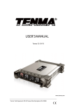
CE2000
H8S Series Compact Emulator
Microcomputer Development Environment System
2003.10
- Blank Page -
User’s Manual
Published by : Renesas System Solutions Asia Pte. Ltd.
Date
: October 3rd, 2003, Version 2.0
Copyright(C) Renesas System Solutions Asia Pte. Ltd. All rights reserved.
Trademarks
a) General
All brand or product names used in this manual are trademarks or registered trademarks of their respective
companies or organizations.
b) Specific
Microsoft, MS and MS-DOS are registered trademarks.
Windows and Windows NT are trademarks of Microsoft Corporation.
Pentium is a registered trademark of Intel.
IMPORTANT INFORMATION
READ this user’s manual before using this emulator product.
KEEP the user’s manual handy for future reference.
Do not attempt to use the product until you fully understand its mechanism.
ALExxxx & CExxxx Emulator:
Throughout this document, the term “ALExxxx emulator” & “CExxxx emulator” shall be defined as the
ALExxxx or CExxxx emulator, user system interface cable, PC interface board, and optional SIMM
memory module produced only by Renesas System Solutions Asia Pte. Ltd. excludes all subsidiary
products.
The user system or a host computer is not included in this definition.
Purpose of the Emulator Product:
This emulator product is a software and hardware development tool for systems employing the H8S
series microcomputer. This emulator product must only be used for the above purpose.
Improvement Policy:
Renesas System Solutions Asia Pte. Ltd. (hereafter collectively referred to as Renesas) pursues a policy of
continuing improvement in design, performance, and safety of the emulator product. Renesas reserves
the right to change, wholly or partially, the specifications, design, user’s manual, and other
documentation at any time without notice.
Target User of the Product:
This product should only be used by those who have carefully read and thoroughly understood the
information as well as restrictions contained in the user’s manual. Do not attempt to use the product
until you fully understand its mechanism. It is highly recommended that first-time users. Be instructed
by users that are well versed in the operation of emulator product.
LIMITED WARRANTY
Renesas warrants its products to be manufactured in accordance with published
specifications and free from defects in material and/or workmanship. The
foregoing warranty does not cover damage caused by fair wear and tear, abnormal
store condition, incorrect use, accidental misuse, abuse, neglect, corruption,
misapplication, addition or modification or by the use with other hardware or
software, as the case may be, with which the product is incompatible. No warranty
of fitness for a particular purpose is offered. The user assumes the entire risk of
using the product. Any liability of Renesas is limited exclusively to the replacement
of defective materials or workmanship.
DISCLAIMER
RENESAS MAKES NO WARRANTIES, EITHER EXPRESS OR IMPLED,
ORAL OR WRITTEN, EXCEPT AS PROVIDED HEREIN, INCLUDING
WITHOUT
LIMITATION
THEREOF,
WARRANTIES
AS
TO
MARKETABILITY,
MECRCHANTABILITY,
FITNESS
FOR
ANY
PARTICULAR PURPOSE OR USE, OR AGAINST INFRINGEMENT OF
ANY PATENT. IN NO EVENT SHALL RENESAS BE LIABLE FOR ANY
DIRECT, INCIDENTAL OR CONSEQUENTIAL DAMAGES OF ANY
NATURE, OR LOSSES OR EXPENSES RESULTING FROM ANY
DEFECTIVE EMULATOR PRODUCT, THE USE OF ANY EMULATOR
PRODUCT OR ITS DOCUMENTATION, EVEN IF ADVISED OF THE
POSSIBILITY OF SUCH DAMAGES. EXCEPT AS EXPRESSLY STATED
OTHERWISE IN THIS WARRANTY, THIS EMULATOR PRODUCT IS
SOLD “AS IS”. AND YOU MUST ASSUME ALL RISK FOR THE USE AND
RESULTS OBTAINED FROM THE EMULATOR PRODUCT.
State Law:
Some states do not allow the exclusion or limitation of implied warranty or liability for incidental or
consequential damages, so the above limitation or exclusion may not apply to you. This warranty gives
you specific legal rights, and you may have other rights which may vary from state to state.
The Warranty is Void in the Following Cases:
Renesas shall have no liability or legal responsibility for any problems caused by misuse, abuse,
misapplication, neglect, improper handling, installation, repair or modifications of the emulator product
without Renesas’s prior written consent or any problems caused by the user system.
Restrictions:
1. Earthing (applies only to manual for Renesas hardware products)
This hardware is designed for use with equipment that is fully earthed.
Ensure that all equipments used are appropriately earthed.
Failure to do so could lead to danger for the operator or damaged to equipments.
2. Electrostatic Discharge Precautions (applies only to manuals for Renesas hardware products)
This hardware contains devices that are sensitive to electrostatic discharge.
Ensure appropriate precautions are observed during handling and accessing connections.
Failure to do so could result in damage to the equipment.
All Right Reserved:
This user’s manual and emulator product are copyrighted and all rights are reserved by Renesas. No
part of this user’s manual, all or part, any be reproduced or duplicated in any form, in hardcopy or
machine-readable form, by any means available without Renesas‘s prior written consent.
Other Important Things to Keep in Mind:
1. Circuitry and other examples described herein are meant merely to indicate the
characteristics and performance of Renesas Technology‘s semiconductor products.
Renesas assumes no responsibility for any intellectual property claims or other problems
that may result from applications based on the examples described herein.
2. No license is granted by implication or otherwise under any patents or other rights of any
third party or Renesas.
3. MEDICAL APPLICATIONS: Renesas Technology’s products are not authorized for use in
MEDICAL APPLICATIONS without the written consent of the appropriate officer of
Renesas Technology (Asia Sales company). Such use includes, but is not limited to, use in
life support systems. Buyers of Renesas Technology’s products are requested to notify the
relevant Renesas Technology (Asia Sales offices) when planning to use the products in
MEDICAL APPLICATIONS.
Figures:
Some figures in this user’s manual may show items different from your actual system.
Limited Anticipation of Danger:
Renesas cannot anticipate every possible circumstance that might involve a potential hazard. The
warnings in this user’s manual and on the emulator product are therefore not all inclusive. Therefore,
you must use the emulator product safely at your own risk.
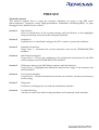
PREFACE
About this manual
This manual explains how to setup the Compact Emulator for usage of the H8S series
microcomputers. Operation using High-performance Embedded Workshop(HEW) as pure
debugger is also detailed in the context.
Section 1
Introduction
Gives an introduction to the system package and specification. It also highlights
the precautionary measures when using the emulator.
Section 2
Installation
Explains how to install and configure the PC in order to operate the emulator.
Section 3
Emulation Functions
Usage Note 1 – Describes the various functions used in the CE2000-H8S/2238
emulator.
Section 4
H8S Function Support
Usage Note 2 – Covers the emulation of the peripherals and features for the H8S
microcomputer in the CE2000-H8S/2238 emulator.
Section 5
Differences between the H8S Microcomputer and the Emulator
Usage Note 3 – Highlights the differences between the usage of the emulator and
the actual MCU.
Section 6
User System Interface
Usage Note 4 – Details information about the user interface circuitry and memory
access timing
Section 7
Diagnostic
Performs a self-diagnostic test with the standalone emulator.
Section 8
Trouble-Shooting
Advises on some basic fault locating methods and commonly made mistakes.
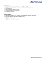
Assumptions
This manual assumes that the user has a working knowledge of
•
•
•
•
•
High-performance Embedded Workshop (Compiler, Assembler and Linker)
H8S Architecture
General Hardware Interface Circuitry
General Personal Computer Operation
MS-Window programs
Related Manuals:
• H8S, H8/300 Series C/C++ Compiler Package Manual (Installed with HEW)
• High-performance Embedded Workshop 2 help
• H8S Series Hardware Manual
• SODIMM User’s Manual
• CE2000 User Cable User’s Manual
Table of Contents
SECTION 1.
INTRODUCTION............................................................................................................. 1
1.1
1.2
1.2.1
1.2.2
1.2.3
1.3
1.4
1.5
1.6
OVERVIEW .......................................................................................................................... 1
PACKAGE CONTENTS .......................................................................................................... 2
Hardware Components ........................................................................................................ 2
Software Components ........................................................................................................ 2
Optional Components ........................................................................................................ 2
SYSTEM REQUIREMENT....................................................................................................... 3
SUPPORTED MCU SERIES BY CE2000-H8S/2238 EMULATOR ........................................... 3
SUMMARY OF CE2000-H8S/2238 EMULATOR FUNCTIONS ................................................ 4
PRECAUTIONARY MEASURES .............................................................................................. 7
SECTION 2.
SETUP................................................................................................................................ 9
2.1
2.2
2.3
2.4
2.5
2.6
2.7
2.7.1
2.8
2.8.1
2.9
2.9.1
2.9.2
2.9.3
2.9.4
2.9.5
2.10
2.11
2.11.1
2.11.2
2.12
EXPRESS SETUP STEPS ........................................................................................................ 9
INSTALLING HEW SOFTWARE........................................................................................... 10
INSTALLING THE USB DRIVER.......................................................................................... 12
CE PROGRAMMER (OS AND LOGIC UPGRADE)................................................................. 15
INSTALLATION DETAILS .................................................................................................... 17
POWER UP THE EMULATOR ............................................................................................... 18
CHECKING THE SYSTEM (STANDALONE MODE)................................................................. 18
LED indication................................................................................................................. 18
ACTIVATION OF THE EMULATION SYSTEM ........................................................................ 19
Creating new workspace.................................................................................................. 19
CONFIGURE THE PLATFORM .............................................................................................. 20
Device and Package Selection ......................................................................................... 21
Operating Mode Selection ............................................................................................... 21
Clock Selection................................................................................................................. 21
User Signal Masking Control (RESET, NMI & STBY).................................................... 21
Downloading of Emulation Function (Programmable Function Generator).................. 21
MEMORY MAPPING ........................................................................................................... 22
CONNECTION TO TARGET SYSTEM .................................................................................... 23
Target Power Supply........................................................................................................ 23
Types of User Interface Cable ......................................................................................... 23
OPTIONAL SODIMM MEMORY SELECTION ..................................................................... 25
SECTION 3.
EMULATION FUNCTIONS ......................................................................................... 28
3.1
3.1.1
3.1.2
3.2
3.3
3.4
3.5
3.6
3.7
3.7.1
3.7.2
OVERVIEW ........................................................................................................................ 28
Emulation ......................................................................................................................... 28
High-performance Embedded Workshop(HEW) ............................................................. 28
PROGRAMMABLE FUNCTION GENERATOR (PFG).............................................................. 30
PIN VIEW .......................................................................................................................... 30
GO (RESET GO, GO AT PC, GOTO CURSOR) ..................................................................... 30
RESET CPU....................................................................................................................... 30
SINGLE-STEP ..................................................................................................................... 30
BREAK FUNCTIONS ........................................................................................................... 31
Event Breakpoint.............................................................................................................. 32
PFG Function – PFG Breakpoint.................................................................................... 32
3.8
3.9
3.10
3.11
3.12
3.13
3.14
3.15
RUN TIME MEASUREMENT ................................................................................................ 32
PFG FUNCTION - TRACE ................................................................................................... 32
MEMORY FUNCTIONS........................................................................................................ 33
PARALLEL-ON-THE-FLY (POTF) ..................................................................................... 33
MEMORY MAPPING ........................................................................................................... 33
CPU AND I/O REGISTERS ACCESS .................................................................................... 34
SESSION ............................................................................................................................ 35
C-SOURCE LEVEL DEBUGGING.......................................................................................... 35
SECTION 4.
H8S FUNCTION SUPPORTED.................................................................................... 36
4.1
4.2
4.2.1
4.2.2
4.2.3
4.2.4
4.3
4.3.1
4.3.2
4.3.3
4.4
4.5
4.6
4.7
4.8
4.9
4.10
4.11
4.12
4.13
4.14
MCU OPERATING MODE SETTING .................................................................................... 36
MEMORY AREA................................................................................................................. 36
INTERNAL ROM AREA ..................................................................................................... 36
INTERNAL RAM AREA ..................................................................................................... 36
INTERNAL I/O AREA ......................................................................................................... 36
EXTERNAL AREA .............................................................................................................. 37
LOW POWER MODE ........................................................................................................... 37
Hardware Standby Mode ................................................................................................. 37
Sleep and Software Standby Modes ................................................................................. 37
Medium Speed and Module Stop Modes .......................................................................... 37
INTERRUPTS ...................................................................................................................... 38
CONTROL INPUT SIGNALS (RES, NMI, STBY) ................................................................ 38
WATCH DOG TIMER (WDT) ............................................................................................. 38
16-BIT TIMER PULSE UNIT (TPU) AND 8-BIT TIMER ......................................................... 38
SERIAL COMMUNICATIONS INTERFACE (SCI) ................................................................... 38
PROGRAMMABLE PULSE GENERATOR (PPG) .................................................................... 38
DMA CONTROLLER (DMAC) .......................................................................................... 38
DATA TRANSFER CONTROLLER (DTC) ............................................................................. 39
BUS STATE CONTROLLER ................................................................................................. 39
I/O PORTS ......................................................................................................................... 39
A/D CONVERTER .............................................................................................................. 39
SECTION 5.
DIFFERENCES BETWEEN H8S MICROCOMPUTER AND EMULATOR ........ 40
5.1
5.2
POWER UP AND RESET ....................................................................................................... 40
USER INTERFACE .............................................................................................................. 41
SECTION 6.
USER SYSTEM INTERFACE ...................................................................................... 42
SECTION 7.
TUTORIAL..................................................................................................................... 46
7.1
7.2
7.3
7.4
7.4.1
7.5
7.5.1
7.5.2
7.6
7.6.1
7.6.2
INTRODUCTION ................................................................................................................ 46
OVERVIEW ........................................................................................................................ 46
HOW THE TUTORIAL PROGRAM WORKS ........................................................................ 47
RUNNING HEW............................................................................................................... 49
Opening Tutorial workspace............................................................................................ 49
SETTING UP THE HEW(PURE DEBUGGER) FOR CE2000-H8S/2238 .............................. 50
Configuring the Platform ................................................................................................ 50
Mapping the Memory ...................................................................................................... 51
DOWNLOADING THE TUTORIAL PROGRAM .................................................................... 53
Loading the Download Module........................................................................................ 53
Displaying the Program Listing...................................................................................... 53
7.7
7.7.1
7.7.2
7.7.3
7.7.4
7.8
7.8.1
7.8.2
7.9
7.9.1
7.10
7.10.1
7.11
7.12
7.12.1
7.13
7.14
USING BREAKPOINTS ....................................................................................................... 54
Setting a Program Count (PC) Breakpoint ..................................................................... 54
Executing the Program .................................................................................................... 55
Reviewing the Breakpoints .............................................................................................. 56
Examining MCU Registers ............................................................................................. 57
EXAMINING MEMORY AND VARIABLES .......................................................................... 58
Viewing Memory ............................................................................................................. 58
Watching Variables.......................................................................................................... 59
STEPPING THROUGH A PROGRAM ................................................................................... 61
Stepping ........................................................................................................................... 61
USING THE PFG BREAKPOINT ......................................................................................... 62
Defining a PFG Breakpoint ............................................................................................. 62
WATCHING LOCAL VARIABLES....................................................................................... 65
USING THE TRACE BUFFER .............................................................................................. 66
Displaying the Trace Buffer............................................................................................. 66
PIN VIEW .......................................................................................................................... 67
SAVE THE SESSION ........................................................................................................... 67
SECTION 8. DIAGNOSTIC..................................................................................................................... 68
8.1
STANDALONE SELF TEST .................................................................................................. 68
SECTION 9. TROUBLE-SHOOTING .................................................................................................... 69
APPENDIX A : USER CONNECTOR PIN ASSIGNMENT .............................................................. A-1
APPENDIX B : USER CONNECTOR SPECIFICATION ................................................................. B-1
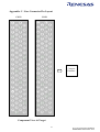
APPENDIX C : USER CONNECTOR PIN LAYOUT ........................................................................ C-1
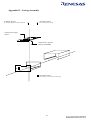
APPENDIX D : CASING ASSEMBLY ................................................................................................. D-1
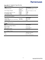
APPENDIX E : TECHNICAL SPECIFICATION ............................................................................... E-1
APPENDIX F : FREQUENTLY ASKED QUESTIONS ......................................................................F-1
RENESAS TECHNOLOGY (ASIA SALES OFFICES)
List of Figures
Figure 1-1
Figure 1-2
Figure 2-1
Figure 2-2
Figure 2-3
Figure 2-4
Figure 2-5
Figure 2-6
Figure 2-7
Figure 2-8
Figure 2-9
Figure 2-10
Figure 2-11
Figure 2-12
Figure 2-13
Figure 2-14
Figure 2-15
Figure 2-16
Figure 2-17
Figure 2-18
Figure 2-19
Figure 2-20
Figure 2-21
Figure 2-22
Figure 2-23
Figure 2-24
Figure 2-25
Figure 3-1
Figure 3-2
Figure 6-1
Figure 6-2
Figure 7-1
Figure 7-2
Figure 7-3
Figure 7-4
Figure 7-5
Figure 7-6
Figure 7-7
Figure 7-8
Figure 7-9
Figure 7-10
Figure 7-11
Figure 7-12
Figure 7-13
Figure 7-14
Figure 7-15
Figure 7-16
CE2000-H8S/2238 Emulator ............................................................................................. 1
CE2000-H8S/2238 Emulator Package............................................................................... 2
Basic Setup of CE2000-H8S/2238 Emulator..................................................................... 9
Compact Emulator ............................................................................................................. 9
Installing HEW package with Tool chain ........................................................................ 10
Installing HEW(Pure Debugger)...................................................................................... 11
Found New Device........................................................................................................... 12
Locate Driver Files........................................................................................................... 12
Selecting the USB Driver Location ................................................................................. 13
Win2K Driver Location ................................................................................................... 13
Win 9x Driver Location ................................................................................................... 14
Selected Driver File Window........................................................................................... 14
Compact Emulator USB Driver Installed ........................................................................ 15
CE Programmer Window................................................................................................. 16
CE OS and Logic Programming ...................................................................................... 16
End of Programming........................................................................................................ 17
HEW Start up Menu......................................................................................................... 17
Power–supply Plug .......................................................................................................... 18
Execute HEW from Start Menu ....................................................................................... 19
Creating new workspace .................................................................................................. 20
Configure Platform dialog ............................................................................................... 20
Memory Mapping dialog ................................................................................................. 22
Editing the Memory Mapping.......................................................................................... 23
User Interface Cable – Direct Connection ....................................................................... 24
User Interface Cable – Actual Footprint .......................................................................... 24
Addition of Optional Memory Address Range ................................................................ 25
Memory Mapping Window.............................................................................................. 26
HEW desktop window ..................................................................................................... 29
Modification of Mapping Memory .................................................................................. 34
Basic Bus Cycle Timing in Expanded mode ................................................................... 43
Interfacing Circuitry......................................................................................................... 44
Execute HEW from Start Menu ....................................................................................... 49
Open Tutorial workspace ................................................................................................. 49
Configure Platform dialog ............................................................................................... 50
Memory Mapping Dialog................................................................................................. 51
Memory page of Status window ...................................................................................... 51
Edit Memory Mapping Dialog......................................................................................... 52
Debug Settings Dialog ..................................................................................................... 53
resetprg.c file after RESET CPU ..................................................................................... 54
Setting a Breakpoint......................................................................................................... 54
Program Break ................................................................................................................. 55
Platform page of Status Window ..................................................................................... 55
Eventpoints Window.................................................................................................... 56
Popup menus in Eventpoints Window...................................................................... 56
CPU Registers Window................................................................................................ 57
Changing Register Value ................................................................................................. 57
Open Memory Window ............................................................................................... 58
Figure 7-17
Figure 7-18
Figure 7-19
Figure 7-20
Figure 7-21
Figure 7-22
Figure 7-23
Figure 7-24
Figure 7-25
Figure 7-26
Figure 7-27
Figure 7-28
Figure 7-29
Figure 7-30
Figure 7-31
Figure 7-32
Memory Window .......................................................................................................... 58
Instant Watch dialog..................................................................................................... 59
Watch Window.............................................................................................................. 59
Add Watch Dialog ........................................................................................................ 60
Watch Window.............................................................................................................. 60
Displaying Individual Elements in an Array............................................................ 61
Step In ............................................................................................................................. 61
Step Over ........................................................................................................................ 62
Breakpoint Setting Dialog............................................................................................ 63
PFG Programming ........................................................................................................ 63
Eventpoints Window........................................................................................................ 64
PFG Break....................................................................................................................... 64
Locals Window.............................................................................................................. 65
Displaying Individual Elements in an Array............................................................ 65
Trace Window ............................................................................................................... 66
Pin View Window ......................................................................................................... 67
List of Tables
Table 1-1
Table 3-1
Table 4-1
Table 5-1
CE2000-H8S/2238 Emulator Functions ............................................................................ 4
Types of Breaks Encountered During Emulation. ........................................................... 31
MCU Operating Modes.................................................................................................... 36
Differences between H8S and Emulator.......................................................................... 40
Section 1. Introduction
1.1
Overview
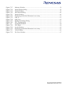
The CE2000-H8S/2238 Compact Emulator is one of the Renesas’s Development Tool series. It is produced
as a cost-effective, easy-to-use support tools.
The CE2000-H8S/2238 emulator has an easy to setup USB link and a common user-friendly Windowsbased interface High-performance Embedded Workshop(HEW). Its flexibility is evident in its Programmable
Function Generator (PFG) which allows user to select and download different emulation features. It has a
built-in Self Test module that will inform user of its working condition through the LED indicator.
Moreover, it has integrated a PinView module, that allow user to have an instant graphical view of the
microcomputer pins’ status.
The CE2000-H8S/2238 emulator can be used as a standalone unit for software development and
debugging. It can also be connected to a target system via a user interface cable for troubleshooting
user’s hardware. It is an indispensable tool that caters to the needs of an embedded designer.
Figure 1-1
CE2000-H8S/2238 Emulator
1
1.2
Package Contents
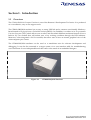
The CE2000-H8S/2238 emulator is supplied in a package containing the following components:
CE2000
PC Interface Cable - USB
CD – HEW,
User Manual,
FAQ
CE2000
H8S SERIES
Emulator
CE Standard User Cable
User Cable Header
Power Supply
Figure 1-2
CE2000-H8S/2238 Emulator Package
1.2.1 Hardware Components
The hardware components included in the package are listed below.
• 1 x CE2000-H8S/2238 emulator
• 1 x PC interface cable – USB cable
• 1 x 300mm KEL user interface cable to connect to target system (Part No.: 8822E-080-171-30-AC)
• 1 x 400mm KEL user interface cable to connect to target system (Part No.: 8822E-080-171-40-AC)
• 2 x KEL connector plugs for the target system (Part No.: 8830E-080-170S)
• 1 x 5V-2.6A power supply adaptor (Ratings: 110-240V/50-60Hz)
1.2.2 Software Components
The software components included in the package are listed below.
• 1 x CD containing HEW(Pure Debugger) Installation, user’s manual and FAQ. The HEW(Pure
Debugger) does not include Renesas’s Toolchain of Compiler.
Before proceeding, user has to check that all the items listed in the packing list. Please contact the
relevant Renesas Sales Office if any item is missing.
1.2.3 Optional Components
The following items can be purchased to further enhance the emulation capability:
• Actual footprint user cable
• 2Mbytes of SODIMM optional memory
2
1.3
System Requirement
The following items are not supplied but they are required to be used with the CE2000-H8S/2238
emulator.
• A minimum PentiumTM or equivalent based processor personal computer with USB version 1.1.
• Microsoft Windows 98(2nd Edition)/Me/2000/Xp
• Memory capacity: at least 128 Mbytes; 256 Mbytes or more recommended.
• Hard disk drive: 100 MB or more (capacity necessary for full installation)
1.4
•
•
•
•
•
•
Supported MCU Series by CE2000-H8S/2238 Emulator
H8S/2214 series
H8S/2215 series
H8S/2238 series
H8S/2237 series
H8S/2227 series
H8S/2239 series
- H8S/2214
- H8S/2215
- H8S/2236(R)(W), 2238(R)(W)
- H8S/2233, 2235, 2237
- H8S/2223, 2224, 2225, 2227
- H8S/2239
3
1.5
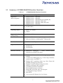
Summary of CE2000-H8S/2238 Emulator Functions
Table 1-1
Items
Supported
Microcomputers
Operating Frequency
Operating Modes
CE2000-H8S/2238 Emulator Functions
Specifications
- H8S/2214
- H8S/2215
- H8S/2236(R )(W), 2238(R )(W)
- H8S/2233, 2235, 2237
- H8S/2223, 2224, 2225, 2227
- H8S/2239
•
•
•
•
•
•
•
•
H8S/2214 series
H8S/2215 series
H8S/2238 series
H8S/2237 series
H8S/2227 series
H8S/2239 series
2 MHz (Min)
16 MHz (Max)
•
•
Mode 5, 6, 7 and 8.
Target
Supported Operating •
Voltage Range
Host Machine
•
•
2.5 Volts - 5 Volts.
Minimum PentiumTM or equivalent processor PC.
Microsoft Windows 2000/Xp/98(2nd Edition)/Me.
Host Interface
•
USB Ver 1.1 (12Mbps).
Supported File Formats
•
•
•
Motorola S-type.
ELF/Dwarf.
ELF/Dwarf2.
Interface Software
•
HEW(Pure Debugger) : 32-bit
interface providing on-line help.
Emulation Functions
•
Perform real-time emulation of a target program at 216MHz.
C-source level debugging (e.g. C-level step execution,
instant watch, view labels…).
Display MCU operating status (e.g. Run, Sleep and
Standby) during User run mode.
Display accessed address during execution.
Modify and display MCU registers.
Assemble instruction mnemonics.
Dis-assemble memory contents.
Radix (Bin, Octal, Dec, Hex, ASCII) input.
Loading and saving of session.
Reset MCU.
Go at current PC/ Reset Go/ Go to Cursor
•
•
•
•
•
•
•
•
•
•
4
Windows-based
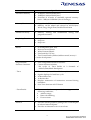
Items
Emulation Memory
•
•
•
Specifications
512Kbytes internal ROM (max)
128Kbytes internal RAM (max)
Provision of 4 banks of selectable optional memory
block − 2Mbytes SODIMM. (Not in Package)
Memory Functions
•
•
Copy, Search, Fill, Load and Save memory functions.
Memory can be edited and viewed in ASCII/ Byte/
Word/ Long/ Single Float/ Double Float format
Parallel On the Fly
•
Memory viewing and modification during user
program execution.
Single Step Functions
•
•
•
Step In.
Step Out.
Step Over.
Breaks
• PC breakpoints (max. 256).
• Reserved Access Break.
• Write-Protected Break.
• User break by ESC key.
• Two Events breaks (address/address mask /access)**.
** under development
Programmable
Function Generator
•
•
User configurable emulator functions
Current function includes:
256 cycles of Trace Buffer & 2 channels of
Address/Data/Mask Breakpoints.
- Trace
•
•
•
•
•
Trace memory size: 64-bit x 256 bus cycle
Signals displayed of each bus cycle:
24-bit address bus.
16-bit data bus.
Displays mnemonics of instructions executed during
emulation.
Save Trace data into ASCII format
•
- Event Breaks
•
Two event breaks are provided to trigger on the
following conditions;
• Address range
• Data with Masking
• Event counter
PinView
•
Provides instant graphical package view of all the pins
of selected microcomputer.
Provides an alternative view in text form.
•
5
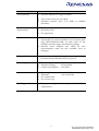
Items
Clock selection
•
Specifications
Software selection of 2 types of clocks:
•
•
User system clock (via user cable)
Emulator internal clock 2−16 MHz at 100KHz
resolution
Execution time
measurement
•
•
•
Measure the start (run) till end (break) of an execution.
Resolution: 50ns
No upper limit
User Cable interface
•
Two fine-pitch user cable assemblies (KEL-8822E-080171-040-AC) are used to interface to two 1.27mm pitch
plug (KEL-8830E-080-170S) on both sides of the
emulator and user target. (Provided in package)
Selected actual footprint user cables for each
microcomputer series are also available. (Not in
package)
•
Voltage Follower
•
Automatic tracking of the target system supply voltage
to ensure that the emulator draws no power.
Power Supply
•
•
•
Power Adaptor Input: 100-240 Vac, 50-60 Hz
Emulator Voltage
: 5V Regulated
Current consumption : 2.6A (max)
Environmental
•
•
•
•
Operating Temperature : 10ºC to 35ºC
Humidity
: 30% to 85% RH
No condensation
No corrosive gas
Field Upgrade
•
Re-programming of emulator logic and flash OS via
USB interface.
6
1.6
Precautionary Measures
The emulator must be handled with care. Otherwise, it may not work as intended.
Before Power On
• Check all components by referring to the packing list
• Never place heavy objects on the casing
Observe the following conditions in which the emulator is to be used:
• Keep out of direct sunlight or heat
• Use in an enviroment with constant room temperature and humidity
• Protect the emulator from dust
• Avoid subjecting the emulator to excessive vibration
• Protect the emulator from excessive impact and stresses
• Check the emulators’ specifications such as power output, voltage, and frequency before connecting
the power supply,
• When moving the emulator, take care to package with good protective box or otherwise damage it.
Pay special attention to exposed parts such as power switch and I/O connectors
• Never allow exposed power supply to come into contact with the emulator casing which is
grounded.
7
- Blank Page -
8
Section 2. Setup
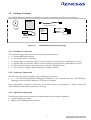
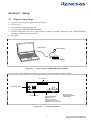
2.1
•
•
•
•
•
•
Express Setup Steps
Unpack and verify parts against the packing list.
Power up PC.
Install HEW by running setup file.
Power up the CE2000-H8S/2238 emulator.
Connect USB cable from PC to the emulator within 10 seconds. Otherwise, the CE2000-H8S/2238
emulator will go into Self Test mode.
Run HEW.
Power Supply
USB Interface
Compact Emulator
Figure 2-1
Basic Setup of CE2000-H8S/2238 Emulator
The following topics detail the essential steps before proper emulation can be started.
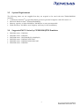
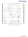
User Connector
Power Supply Input
-
+ PC I/F
PC USB Connector
Figure 2-2
PWR RUN
POWER Status LED
-RED: Power On
-ORANGE: Self Test
-ORANGE: PC Detection
-BLINK: Self Test Cycle ended
Compact Emulator
9
RUN Status LED
- RED: Self Test Failed
- GREEN: Run
2.2
Installing HEW software
HEW(Pure Debugger) for CE2000-H8S/2238 can be used alone as pure debugger which users can only
do debugging on the download module.
If a user has HEW compiler package with Hitachi’s Toolchain, he can use HEW(Pure Debugger) for
CE2000-H8S/2238 with integration with the Toolchain. This allows users to do debugging and compiling
by using only 1 application.
To install HEW(Pure Debugger) for CE2000-H8S/2238 only, the installation is simple by just
running the CE2000.exe.
In order to use HEW(Pure Debugger) for CE2000-H8S/2238 and H8S,H8/300 Series C/C++
Compiler, a user need to install the hew package with tool chain first and then install HEW(Pure
Debugger) for CE2000-H8S/2238 at the same location/directory.
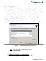
Step:
1. Install HEW package with tool chain.
Figure 2-3
Installing HEW package with Tool chain
Note: The location chosen for installation in this example is
C:\Program Files\HEW
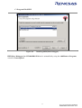
2. Install HEW(Pure Debugger) for CE2000-H8S/2238
Notes : Users have to install in the same location as in Step 1, thus
10
C:\Program Files\HEW
Figure 2-4
Installing HEW(Pure Debugger)
HEW(Pure Debugger) for CE2000-H8S/2238 can be uninstalled by using the Add/Remove Programs
wizard of Control panel.
11
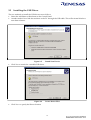
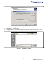
2.3
Installing the USB Driver
The two methods to install the USB drivers are as follows:
• Select the Add/Remove Hardware in the Control Panel.
• Another method is to link the emulator to the PC through the USB cable. This will activate Windows
auto-detect feature.
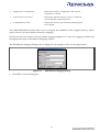
Figure 2-5
•
Click Next to search for a suitable USB driver
Figure 2-6
•
Found New Device
Locate Driver Files
Click Next to specify the Driver location
12
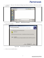
Figure 2-7
•
•
Selecting the USB Driver Location
Click on Browse… and select either
C:\ProgramFiles\hew\Tools\Renesas\DebugComp\Platform\Emulator\CE2238\Driver\Win2K
directory or
Figure 2-8
Win2K Driver Location
13
•
C:\Program
directory
Files\hew\Tools\Renesas\DebugComp\Platform\Emulator\CE2238\Driver\Win9x
Figure 2-9
•
Select the file available
Figure 2-10
•
Win 9x Driver Location
Selected Driver File Window
Click on Next to install the driver
14
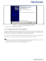
Figure 2-11
•
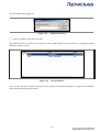
2.4
Compact Emulator USB Driver Installed
Click on Finish to complete the installation
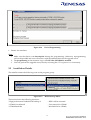
CE Programmer (OS and Logic Upgrade)
During the installation of the HEW, the installer checks the OS and Logic version of the emulator (if it is
connected). If it is outdated, the CE Programmer can be activated to upgrade the OS and Logic through
the USB interface (Ensure that the optional memory SODIMM is disconnected).
User can also activate the CE Programmer at any time to upgrade the system. The CE Programmer is
located in the “CE Programmer” sub-directory of the directory where HEW is installed.
Step:
• If HEW is connected to emulator, Exit HEW. Restart the emulator with USB connection to PC (This is
to ensure that the emulator is in the correct state before the upgrading).
• Click on the CE Programmer.exe to activate the programmer.
15
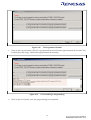
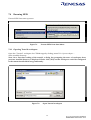
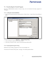
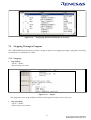
Figure 2-12
•
Click on the Program button (The OS is programmed first and it takes approximately 25 seconds. This
is followed by the Logic, which takes approximately 40 seconds).
Figure 2-13
•
CE Programmer Window
CE OS and Logic Programming
Click on the Close button, once the programming has completed.
16
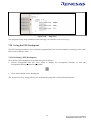
Figure 2-14
•
End of Programming
Restart the emulator.
Note:
1. Make sure that there is no interruption during the programming. Otherwise, reprogramming
will not be possible and user will need to send the emulator back for the upgrade work.
2. The programming of the emulator Logic will fail if the SODIMM is attached.
3. User can perform the upgrade at any time by executing the CE Programmer.exe if necessary.
2.5
Installation Details
The installer creates the following icons in the program group:
Figure 2-15
HEW Start up Menu
These menu have the following functions:
“High-performance Embedded Workshop 3”
“CE2000 User Manual”
“CE2000 Read Me”
: HEW will be activated.
: User manual for CE2000
: Read Me file for CE2000
17
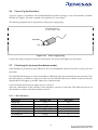
2.6
Power Up the Emulator
A power supply is included in the CE2000-H8S/2238 emulator package. It can accommodate 110-240V
50-60Hz AC supply. The unit is capable of a regulated 5V, 2.6A output.
The following diagram shows the polarity of the power-supply plug:
CENTRE POSITIVE
2.1 mm Phone - Jack
GROUND
+5V
Figure 2-16
Power–supply Plug
Connect the plug to the power input of the emulator. The Power LED lights up (red colour).
2.7
Checking the System (Standalone mode)
If the emulator is powered up and USB link to PC is not established within 10 seconds, it will go into self
test mode.
The POWER LED changes its colour from RED to ORANGE when it has entered the self test mode. This
test takes about 1∼2 minutes. At the end of the test, the POWER LED starts to blink. If the test fails, the
adjacent RUN LED lights up in RED. Otherwise, it remains unlit.
For more details about this test, please refer to section 8.
After the confirmation of the condition of the emulator, user has to insert the USB cable and power up
the emulator in order to link the emulator to the PC.
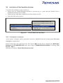
2.7.1 LED indication
Indication
Power Up
Self Test in Process
Self Test Fail
Self Test Pass
Running User Program
PC Detection
X : Don’t Care
POWER LED
Red
Orange
Blinking Orange
Blinking Orange
X
Orange
18
RUN LED
Nil
X
Red
Nil
Green
X
2.8
Activation of the Emulation System
To activate the emulation system, user has to:
• Ensure that the CE2000-H8S/2238 emulator is powered up i.e., check that the POWER LED is
illuminated and the colour is RED.
• Ensure that the USB cable is linked between the emulator and PC.
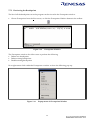
• Select the HEW start up menu.
Figure 2-17
Execute HEW from Start Menu
2.8.1 Creating new workspace
A new project workspace can be generated for device of H8S/2238 Series by clicking menu File->New
workspace as figure below.
Proceed with other steps and chose the CPU Series 2000 and the device supported by HEW(Pure
Debugger) for CE2000-H8S/2238. And, select Target “CE2000-H8S/2238 Emulator” in dialog “New
Project – Step 7”.
Note:Select Toolchain “Hitachi H8S,H8/300 Standard”.
19
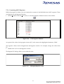
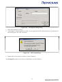
Figure 2-18
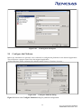
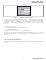
2.9
Creating new workspace
Configure the Platform
Before any emulation can proceed, user is advised to configure the platform for the desired application.
This will ensure a proper control over the targeted application.
All the following can be configured by selecting menu Options->Emulator->Systems….
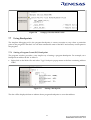
Figure 2-19
Configure Platform dialog
Figure 2-19 shows the Configure Platform dialog for platform configuration.
20
2.9.1 Device and Package Selection
User has to select the desired device and package. The selection will determine the mapping window
setting. The package selection will also determine the type of graphical display in the pinview window.
2.9.2 Operating Mode Selection
There are five mode selections:
• Mode 4
• Mode 5
• Mode 6 [Default]
• Mode 7
• Target Mode
: determined by USER Target system via user cable
NOTE: For ROMless mode operation, user has to make sure that external memory is connected before
any emulation can occur. If user’s target system is not ready, user may map the area to the optional
SODIMM memory for temporary usage.
2.9.3 Clock Selection
User can choose from two different sources: Internal or External Target Clock.
For internal clock, user can key in any frequency from 1MHz to 25MHz, in the step of 100KHz (in
Options->Emulator->Systems …). The emulator will generate the requested clock for the running
processor.
For external target clock, user can either input an oscillating clock into the EXTAL pin, or place a crystal
at the actual footprint user cable (EXTAL and XTAL pins).
2.9.4 User Signal Masking Control (RESET, NMI & STBY)
These signals can be masked by the emulator when user executes the programs. At startup, the RESET
and NMI signals are not masked, whereas STBY signal is masked (in Options->Emulator->Systems …).
Illegal access break can also be enabled in this dialog.
NOTE: If STBY signal is asserted during user run mode, the emulator will enter standby mode, and the
emulator control registers are initialised.
2.9.5 Downloading of Emulation Function (Programmable Function Generator)
User has to download the selected function to the Programmable Function Generator before it can be
used. This has to be done once the emulator is switched off.
Please refer to section 3 for more details.
21
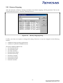
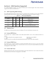
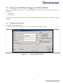
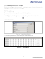
2.10 Memory Mapping
After the selection of Device, Package and Mode, the default mapping will be generated. This can be
viewed under the Options->Emulator->Memory Resource….
Figure 2-20
Memory Mapping dialog
Usually, user does not require to change this setting. However, it may be changed for the following
reasons:
• Addition of target system with memory
• Addition of optional SODIMM memory
The nine available attributes are:
• On Chip Read Write
• On Chip Read Only
• On Chip Guarded
• Emulator Read Write
• Emulator Read Only
• Emulator Guarded
• External Read Write
• External Read Only
• External Guarded
22
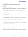
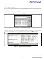
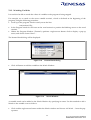
To change the setting, user has to:
• Click on the Add button in the Memory Mapping dialog.
• Key in the desired address at From and To.
• Select the attribute.
Figure 2-21
Editing the Memory Mapping
For the details of the memory mapping, please refer to section 3.
2.11 Connection to Target System
2.11.1 Target Power Supply
The CE2000-H8S/2238 emulator has an automatic voltage follower. Once target is connected (target
connector’s signal: CABLE_IN_N = Lo, refer to the Appendix A), the CE2000-H8S/2238 emulator will
operate at the user supply (2.5V−5V). Otherwise, it will operate at 5V. When target is connected, HEW
will indicate “User Cable : connected” in the status/ platform window.
NOTE:
• Do not connect the user system interface cable to the emulator without user system connection (i.e.
without target user supply).
• Turn on the user system before powering up the emulator.
2.11.2 Types of User Interface Cable
There are two ways to connect the target system to the CE2000 i.e.,
• via an actual footprint user cable (purchase separately), or
• direct connection using the KEL connectors (supplied in the package)
For the actual footprint user cable, user is advised to refer to the Microcomputer Hardware Manual for
the footprint information.
For the direct connection method, the connector information such as pin definitions, layout, dimensions
and part number are detailed in the Appendices A, B and C.
23
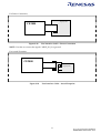
For Direct Connection,
Target System
CE2000
Figure 2-22
User Interface Cable – Direct Connection
NOTE: User has to connect the signal CABLE_IN_N to ground.
For Actual Footprint.
CE2000
Target System
Figure 2-23
User Interface Cable – Actual Footprint
24
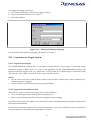
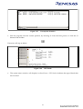
2.12 Optional SODIMM Memory Selection
Optional SODIMM memory is used when user wants to access external memory area when the target
system is not available.
If SODIMM is purchased, user has to open the casing and fix the SODIMM in the correct socket (Please
refer to the SODIMM user manual).
In order to use the SODIMM, user has to enable the memory at the desired address:
• In the Memory mapping dialog, click on Add.
• Key in the desired address at From at To.
• Select the attribute i.e., Emulator read-write, Emulator read only or Emulator Guarded.
NOTE: 2Mbytes (Four banks of 512 Kbytes) of Optional Memory (purchase separately) can be used in
the CE2000-H8S/2238 emulator. User can map the memory (minimum of 32 Bytes to a maximum of
2MBytes) to any space except internal space (e.g. internal ROM, RAM, peripherals, …). If the target
memory is present in the same area as the optional memory, the optional memory will have a higher
priority to be accessed.
e.g.
If user maps the address from H’20000 to H’80002 as Emulator-Read-Write, HEW will allocate 2
banks of memory for the user, to access from area H’20000 to H’8001F.
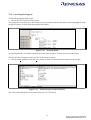
Figure 2-24
Addition of Optional Memory Address Range
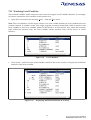
25
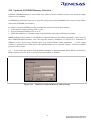
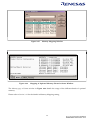
Figure 2-25
Figure 2-26
Memory Mapping Window
Mapping of Optional Memory Shown in Status Window
The Memory page of Status window in Figure 2-26 details the usage of the different banks of optional
memory.
Please refer to Section 3.13 for the details in Memory Mapping setting.
26
- Blank Page -
27
Section 3. Emulation Functions
3.1
Overview
3.1.1 Emulation
The CE2000-H8S/2238 emulator operates in two modes: Break and User modes.
To execute the user program, user can either Single-Step, Run at current program counter or Reset Go. This
will cause it to operate in the User mode. To terminate the User Run state, a break condition has to be
asserted to bring the emulator to the Break mode. This can either be a preset condition(eg. PC Break,
Event Break) or a force break condition (Hit ESC key).
During Break mode, user can manipulate their target system & memory by accessing the I/O, Memory
… windows.
During Run mode, information such as accessed address, CPU states (e.g. instruction fetch cycle, sleep
mode…) and run time can be observed. User can also view and edit the memory contents in the internal
ROM/RAM or optional SODIMM area. This process is named as Parallel On the Fly (POTF).
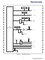
3.1.2 High-performance Embedded Workshop(HEW)
The following figure is a snap shot of the HEW desktop window.
28
Menu
bar
Help
button
Toolbar
Workspace
window
Status
window
Output
window
Figure 3-1
HEW desktop window
The key features of HEW are described in the following sections:
Menus
: Gives user access to the HEW debugging commands for controlling
CE2000 Emulator.
Toolbar
: Provides convenient buttons as shortcuts for the most frequently
used menu commands.
Workspace
Window
: Displays the list of source files.
Output window
: Displays the status of debugger, building process, etc…
Help Button
: Activates context sensitive help on any feature of the HEW user
interface.
29
3.2
Programmable Function Generator (PFG)
This allows user to download the desired emulation function during debugging (in Options->Emulator>System…). At the power-up state, there is no function in the PFG and user has to download the
preferred function before emulation. User can only change the function when the emulator is in break
mode. To access the function after downloading, user has to open up the break or trace window. The
programmed function will remain in the emulator as long as it is not powered down.
As at the current date, the available function is the “Integrated 256 Cycles of Bus Trace and Two Event
Breaks”. More functions will be generated later. Please approach the relevant Renesas Sales Office for
further information.
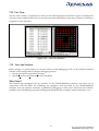
3.3
Pin View
Pin View module shows the pin-state of device in graphical and text forms.
3.4
Go (Reset Go, Go at PC, Goto Cursor)
Real-time execution (in Debug/Go) by the H8S chip based on the user setting. There is no “cycle steal“
during the execution mode.
3.5
Reset CPU
When ”RESET CPU” command is activated, the following actions will take place,
PC
=
Power on Reset vector value
ER7
=
H’FFEFBC
ER0-6
=
H’0
CCR
=
H’80
EXR
=
H’07
The microcomputer is reset.
3.6
Single-Step
There are four types of Single Step:
• Step-In,
• Step-Over, Step-out,
• Step…
Single Step executes the instruction at the current program counter. If an interrupt is asserted, the
interrupt service routine will not be serviced unless a “Go” commands is issued.
Step-In will execute a single instruction only. For C source file, a single step will execute a “single C
source code”. Whereas for an assembly file, a single step will execute a single assembly instruction code.
Step-Over executes multiple Step-In to complete a function execution until it has reached the next
instruction.
30
Step-out performs program stepping out of a function.
Step… will execute multiple Step-in as specified by the user.
3.7
Break Functions
Breaks are events used to interrupt the normal program execution when a specific condition is matched.
There are six types of break in CE2000. These break functions are classified into two classes, mainly
hardware Event and software PC break.
For Hardware Event break, the preset break condition will cause the break event to occur after an
instruction is executed. For Software PC break, the break condition causes the break event to occur
before the break condition.
Table 3-1
Types of Breaks Encountered During Emulation.
Types of Break
1
Event Break**
(Hardware Break)
2
PFG Break
(Hardware Break)
Description
A break occurs when the CPU matches with a condition
specified in the Breakpoint Setting dialog, or when the
pre-fetch cycle of the CPU agrees with the specified
states.
A break occurs when the CPU matches with a condition
specified in the Breakpoint Setting dialog, or when the
pre-fetch cycle of the CPU agrees with the specified
states.
A break occurs at the program address specified in
Breakpoint Setting dialog. The instruction at this address
is replaced with a system instruction before the execution
of code. If a PC breakpoint is detected, the emulation
stops at the specified address before executing the
subsequent instruction.
3
PC Break
(Software Break)
4
User Break
Pressing the ESC key of the host PC generates a break.
5
Reserved Area Break
A reserved area break occurs when user code reads from
or writes to prohibited area of the MCU memory map
6
Write Protect Break
When ROM in the MCU is specified, a write protect
break occurs when attempting to write to the ROM area.
** under development
31
3.7.1 Event Breakpoint
For the CE2000-H8S/2238 emulator, two event breakpoints are supplied permanently. The conditions to
determine the breaks are
• Address
• Access (Read/Write)
The break condition occurs in a “AND” condition. If the factors defined are not fulfilled, the particular
break condition will be ignored. Each factor can be masked or ignored.
Since the event breakpoint is still under development, user can use the PFG Breakpoints instead.
3.7.2 PFG Function – PFG Breakpoint
Two PFG breakpoints can be downloaded into the PFG. The PFG Event Breaks have the following
conditions:
• Address
• Data
• Access (Read/Write)
3.8
Run Time Measurement
The run time counter is set to measure the instances when the user program is executed. The resolution
of the timer is 50ns. There is no time limit for this counter.
The runtime can be observed in the Status window during the run mode.
3.9
PFG Function - Trace
There is no permanent trace provided. However, user can download the Trace Function into the PFG to
keep track of the program. The Trace provided is a 256-cycle trace. The Trace function will display the
last 256 cycles of information upon encountering a break condition.
In each trace cycle, the available displayed data are
• 24-bit Address
• 16-bit Data
• Read / Write
• MCU status
• The Executed Code (C or assembly)
32
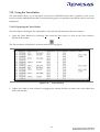
3.10 Memory Functions
General functions such as fill, copy, search, save and load memory are supported, by means of clicking
the mouse button. Modification of memory can be made via byte, word, or long word access.
NOTE: User has to set the bus state controller correctly before the external memory can be accessed.
These functions can be applied on all the three memory type of the emulator, namely:
• On-Chip Memory (internal ROM/RAM)
• Optional SODIMM Memory (2Mbytes SRAM)
• User Target Memory
3.11 Parallel-On-The-Fly (POTF)
POTF feature can be observed in the Monitor window in HEW.
3.12 Memory Mapping
This functions as a traffic controller to direct the MCU to access the intended area of memory. In general,
there are three types of memory area, namely:
• On Chip Memory
• Optional Emulator Memory
• External Target Memory
Two more constraints are set to prevent user’s program from running wild. i.e.
• Write–protect
• Access-inhibit or Guarded
These protections can be allocated to the memory area in minimum unit of 32 bytes resolution.
These constitute nine possible attributes setting:
• On Chip Read Write
• On Chip Read Only
• On Chip Guarded
• Emulator Read Write
• Emulator Read Only
• Emulator Guarded
• External Read Write
• External Read Only
• External Guarded
To change the setting, user has to:
• Click on the Add button in Memory Mapping dialog.
• Key in the desired address at “From and To”. &
• Select the attribute.
33
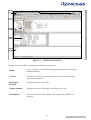
Figure 3-2
Modification of Mapping Memory
At startup, when user select the Device, Package and Mode in the Configure Platform dialog, default
mapping for the application will be generated. This can be viewed under Memory Mapping dialog. In
default, if the device has an external address space, it will be set to be external guarded. Upon connecting
the emulator to a target system or accessing the optional SODIMM, user has to change this default
setting i.e.,
To access external target memory
• Set External Guarded to External Read Write or External Read Only
To access optional SODIMM memory
• Set External Guarded to Emulator Read Write or Emulator Read Only
For the On Chip attributes, user can only change the attributes from Read-Write and Write to Guarded,
but not at any other possibilities. In the case for the Emulator and External attributes, user can set it to any
combination.
3.13 CPU and I/O Registers Access
User can access these registers directly through the Register and I/O windows respectively during break
mode only.
34
3.14 Session
User can retrieve the last emulation enviroment by saving and restoring session. HEW will load the
same session, which comprises of the following:
• Mode settings
• Window positioning
• File loaded
• Clock settings
• Registers value settings
• PFG function loading
3.15 C-source Level Debugging
If user compiles and links the code with the Debug option enabled, the Renesas object format (.abs) file
with the debugging information is generated. This enables user to debug the code in C-source level i.e. ,
• Display code in C source level,
• Step code in C source level,
• View label,
• Goto label (address),
• View local
• Add watches
35
Section 4. H8S Function Supported
The CE2000-H8S/2238 emulator can support the H8S series of microcomputer. The various functions
support for the H8S are detailed below.
4.1
MCU Operating Mode Setting
The CE2000-H8S/2238 emulator supports the four operating modes of the H8S. User can select the MCU
operating mode via the Configure Platform dialog. The following table shows the MCU settings.
Table 4-1
MCU Operating Modes
Operating mode
MD2
MD1
MD0
Mode 4
1
0
0
Mode 5
1
0
1
Mode 6
1
1
0
Mode 7
1
1
1
4.2
Advanced expanded mode w/o internal
ROM (16 bits)
Advanced expanded mode w/o internal
ROM (8 bits)
Advanced expanded mode with internal
ROM
Advanced single chip mode
Memory Area
The H8S has a maximum memory area of 16 Mbytes. The four classification of memory are:
4.2.1 Internal ROM Area
The emulator has a substitute RAM for the H8S internal ROM. Access to this substitute RAM is as
follows:
• Access arising from user program execution
: Read only, write disabled
• HEW
: R/W enabled
Therefore, the user can modify the internal ROM area memory and load the object program.
4.2.2 Internal RAM Area
The emulator has a substitute RAM for the H8S internal RAM. When user tries to access the internal
RAM, this substitute RAM is always accessed instead. User can access the internal RAM area from the
user program or with an HEW.
4.2.3 Internal I/O Area
When the internal I/O area is accessed, the emulator accesses the internal I/O. User can read and write to
the internal I/O area from the user program or with HEW.
36
4.2.4 External Area
The external target area will be accessed as long as the area does not belong to:
• Internal ROM
• Internal RAM
• Internal I/O
• Mapped Emulator Optional Memory
User has to set the area to be read/write or write protected, in order to access the area. Otherwise, the
area will be treated as Access inhibited or Guarded.
The number of accessing states and type of access (e.g. DRAM access) will be determined by the H8S
registers (eg. BSC, WCR1...).
4.3
Low Power Mode
For reduced power consumption, the H8S has medium speed, sleep, module stop, hardware standby,
and software standby mode
4.3.1 Hardware Standby Mode
The hardware standby mode is switched by the STBY signal input. This signal will initialise the
emulator registers. In default, the STBY signal is masked in the Configure Platform dialog.
The status of the STBY signal from the user’s target system can be monitored by HEW.
4.3.2 Sleep and Software Standby Modes
The sleep and software standby modes are switched using the SLEEP instruction. These modes can be
cleared with either the normal clearing function or with the break condition fulfilled (including ‘ESC’
key input). The program will then be put to a stop.
Trace information is not acquired in sleep and software standby modes.
NOTE: When restarting after a break, the code after the SLEEP instruction will be executed.
4.3.3 Medium Speed and Module Stop Modes
These modes are switched by the setting of the I/O registers in the MCU and not controlled by the
emulator.
37
4.4
Interrupts
During emulation, the user can interrupt the H8S. If an interrupt occurs while the emulator is in the
break mode, the interrupt is not processed. However, if an edge-sensitive interrupt occurs while the
emulator is in the break mode, the emulator latches the interrupt and executes the interrupt processing
routine when the GO command is instructed again.
Interrupt request is masked during single step.
4.5
Control Input Signals (RES, NMI, STBY)
The H8S input signals (RES, NMI and STBY) are controlled by the emulator. These signals can be
masked by the HEW. In default, the STBY signal is masked. The RES signal is valid only when emulator
enters run mode.
4.6
Watch Dog Timer (WDT)
The WDT operates during run mode emulation, and does not operate when the emulator is in the break
mode. The timer is disabled at a break and enabled when emulation resumes.
4.7
16-bit Timer Pulse Unit (TPU) and 8-bit Timer
The TPU and the 8-bit timer operate during the break mode as well as the user mode i.e., the timer pins
are valid even when the user program has stopped. The user can rewrite the timer registers with the I/O
window or Memory window.
4.8
Serial Communications Interface (SCI)
The serial communications interface signals are connected to the user system directly from the H8S MCU
in the emulator. Therefore, the interface is valid both in the break and run mode. For example, when
writing data to the TDR (transmit data register) in the I/O or Memory Window, after the serial
communications interface output has been initialized, data is output to the TXD line.
4.9
Programmable Pulse Generator (PPG)
The PPG operates during break and run modes.
4.10 DMA Controller (DMAC)
The DMAC operates during emulation execution and in the break mode. When a transfer request occurs,
the emulator carries out DMA transfer.
38
4.11 Data Transfer Controller (DTC)
The DTC operates during emulation execution and in the break mode. When a transfer request occurs,
the emulator carries out DTC transfer. The DTC RAM data is not accessable during run mode i.e., no
POTF is possible for DTC RAM.
NOTE: The DTC is connected to the area from adress H’FF-EBC0 to H’FF-EFBF in the internal RAM
through a 32 bit bus. Therefore for transfer between the high order 16 bits of the DTC and the internal
RAM, trace information cannot be acquired and no break can be generated.
4.12 Bus State Controller
The H8S bus state controller has a programmable wait mode and a WAIT pin input mode. The
programmable wait mode is valid when the emulation memory or user (target or external) memory is
accessed, but input to the WAIT pin is only valid when the user memory is accessed. Input to the user
WAIT pin is always valid during refresh cycles.
4.13 I/O Ports
The H8S I/O ports can be used as peripheral module I/O pins or as an address/data bus, depending on
the operation mode or internal register settings. The I/O port pins are valid during execution & break
state. User can access or modify the I/O port pins (multiplexed with peripheral module I/O pins) with
the I/O and MEMORY window.
4.14 A/D Converter
The analogue I/O pins are connected to the user system directly from the H8S MCU. Thus the reading
are valid during the execution and break state. Connect the AVCC pin (the VCC pin for the A/D) and the
VREF (reference voltage pin) to the A/D and D/A conversion power supply and the reference power
supply on the user’s system.
NOTE: AVCC and VREF pins must be connected to VCC pins when the A/D and D/A converters are not
used. The conversion precision on the emulator is lower than that of the actual MCU. This is mainly due
to the extra resistance and capacitance introduced in the cabling and printed circuit boards.
39
Section 5. Differences between H8S Microcomputer and
Emulator
5.1
Power up and reset
When the emulator initialises the system or resets the Microcomputer as a result of a command such as
switching the clock, or when the reset command is used, note that the general-purpose registers and part
of the control registers are initialized.
Table 5-1
Status
Emulator
Initialisation
(power on)
Register
PC
Emulator
Power on reset vector value
H8S
Power on reset vector value
ER0 to ER6
H’00000000
Undefined
ER7 (SP)
H’FFEFBC
The I mask is set to 1 and the
other bits are undefined
(B’1-------)
Trace bit is set to 0 and the
interrupt bits are set to 1
(B’0----111)
Undefined
The I mask is set to 1 and the
other bits are undefined
(B’1------)
Trace bit is set to 0 and the
interrupt bits are set to 1
(B’0----111)
PC
Power on reset vector value
Power on reset vector value
ER0 to ER6
Undefined
Undefined
ER7 (SP)
Undefined
The I mask is set to 1 and the
other bits are undefined
(B’1-------)
Trace bit is set to 0 and the
interrupt bits are set to 1
(B’0----111)
Undefined
The I mask is set to 1 and the
other bits are undefined
(B’1------)
Trace bit is set to 0 and the
interrupt bits are set to 1
(B’0----111)
CCR
EXR
Emulator
Initialisation
(reset
command)
Differences between H8S and Emulator
CCR
EXR
40
5.2
User Interface
User may have to adjust the target system as follows:
• The emulator’s user system interface is provided with pull-up resistors and/or a buffer, causing the
signals to be delayed slightly.
• The pull-up resistors will change high-impedance signals to high level signals.
• The Analog to Digital conversion’s resolution will have a slight degradation.
• Load capacitance of the emulator as compared to the actual chip will be larger.
• Crystal oscillator can only used if the actual footprint user cable is used (there is an oscillating
circuitry built on-board). If user uses the direct method of connecting to the target system, the actual
clock signal has to be connected to the EXTAL pin (NOTE: there is no XTAL pin).
• If user uses the direct connection method, the signal (CABLE_IN_N) has to be connected to ground.
Please refer to section 6 for the details of user interface circuitry
41
Section 6. User System Interface
The user target system is connected to the emulator via the interface cable. Interface circuitry is inserted
in between to remove noise and protect the emulator. When connecting the user target system to the
emulator, user has to consider the adjustment of the user system hardware. Compensation for FAN-IN,
FAN-OUT and propagation delays are necessary. In general, the one-way propogation delay of the
cabling is about 4ns. However, the user clock signal is delayed for approximately 25 ns.
All signals are connected to the MCU with no buffering with the exception of
• NMI
• RESET
• STBY
• MD[2..0]
• EXTAL
The emulator does not detect the following signals
• FWE
• OSC1
• OSC2
• CVCC
• XTAL
All port signals are pulled up by a 47K ohm resistor with the exception of all analogue pins (Ports 4 and
9).
All signals satisfy the MCU AC timing specification.
The illustration of the user interface circuitry will be as follows.
42
Figure 6-1
Basic Bus Cycle Timing in Expanded mode
43
User Vcc
PinView
47 ΚΩ
All Port Pins
PinView
Analogue Pins
User Vcc
PinView
47 ΚΩ
RESET
NMI
STBY
MD [0..2]
Emulator
Control
User Vcc
H8S
Microcomputer
PinView
47 ΚΩ
EXTAL
Emulator
Control
User Vcc
User Vcc
Emulator Supply
47 ΚΩ
CABLE_IN_N
VCC
AVCC
AVREF
AVSS
Figure 6-2
Interfacing Circuitry
44
- Blank Page -
45
Section 7. Tutorial
The following describes a sample debugging session, designed to introduce the main features of the
CE2000-H8S/2238 emulator used in conjunction with the High-performance Embedded
Workshop(HEW) software.
The tutorial is designed to run in the CE2000-H8S/2238 emulator’s resident memory so that it can be
used without connecting the CE2000-H8S/2238 emulator to any external user system.
7.1
Introduction
The tutorial is written in C source code.
Before reading this chapter:
• Setup the CE2000-H8S/2238 emulator and verify that it is working correctly with the HEW software.
The CE2000-H8S/2238 emulator need not be connected to any user system when using this tutorial.
• User has to be familiar with the architecture and instruction set of the H8S/2238 Series MCU. For
more information please refer to the H8S/2238 Series Programming Manual and H8S/2238 Series
Hardware Manual.
7.2
Overview
This program is an infinite loop that sort elements based on NAME in the alphabetical order, and AGE
and ID in the numerial ascending order.
The tutorial is provided on the installation disk as the file 2238.c. A compiled version of the tutorial is
provided in Motorola S-Record in the file 2238.mot.
46
7.3
How the Tutorial Program Works
The first part of the program includes a series of header files:
#include "machine.h"
#include "string.h"
The program then gives prototypes for the constants, structures, and function initial values:
#define NAME (short)0
#define AGE (short)1
#define ID
(short)2
#define LENGTH 8
struct namelist {
char name[LENGTH];
short age;
long idcode;
};
struct namelist section1[] = {
"Naoko", 17, 1234,
"Midori", 22, 8888,
"Rie", 19, 7777,
"Eri", 20, 9999,
"Kyoko", 26, 3333,
"",
0, 0
};
int count;
void sort();
Now the main program.
main( )
{
count = 0;
for ( ; ; ){
sort(section1, NAME);
count++;
sort(section1, AGE);
count++;
sort(section1, ID);
count++;
}
}
47
The remainder of the program defines the functions called from main:
void sort(list, key)
struct namelist list[];
short key;
{
short i,j,k;
long min;
char *name;
struct namelist worklist;
switch(key){
case NAME :
for (i = 0 ; *list[i].name != 0 ; i++){
name = list[i].name;
k = i;
for (j = i+1 ; *list[j].name != 0 ; j++){
if (strcmp(list[j].name , name) < 0){
name = list[j].name;
k = j;
}
}
worklist = list[i];
list[i] = list[k];
list[k] = worklist;
}
break;
case AGE :
for (i = 0 ; list[i].age != 0 ; i++){
min = list[i].age;
k = i;
for (j = i+1 ; list[j].age != 0 ; j++){
if (list[j].age < min){
min = list[j].age;
k = j;
}
}
worklist = list[i];
list[i] = list[k];
list[k] = worklist;
}
break;
case ID :
for (i = 0 ; list[i].idcode != 0 ; i++){
min = list[i].idcode;
k = i;
for (j = i+1 ; list[j].idcode != 0 ; j++){
if (list[j].idcode < min){
min = list[j].idcode;
k = j;
}
}
worklist = list[i];
list[i] = list[k];
list[k] = worklist;
}
break;
}
}
48
7.4
Running HEW
Execute HEW from start up menu.
Figure 7-1
Execute HEW from Start Menu
7.4.1 Opening Tutorial workspace
Open the “Tutorial” workspace for CE2000 target by clicking menu File->Open workspace…
in the installed directory.
Note: On a first time loading of the tutorial, a dialog box prompting the move of workspace from
previous installed directory is displayed. Please click [YES] and the workspace would be configured
to the current installed directory permanently.
Figure 7-2
Open Tutorial workspace
49
7.5
Setting up the HEW(Pure Debugger) for CE2000-H8S/2238
Before downloading a program to the CE2000-H8S/2238 emulator, the following items need to be
configured:
• device type
• memory map
The following sections describe how to setup the CE2000-H8S/2238 emulator for running the tutorial
program.
7.5.1 Configuring the Platform
To setup the target configuration:
• Choose menu Options->Emulator->System… to open Configure Platform dialog.
Figure 7-3
Configure Platform dialog
50
7.5.2 Mapping the Memory
The next step is to map the emulation memory of CE2000-H8S/2238 emulator for the application you are
developing.
• To display the current memory mapping, choose Options->Emulator->Memory Resource… menus.
The Memory Mapping dialog… shown in the following figure:.
Figure 7-4
Memory Mapping Dialog
Click on the Close button to end the Memory Mapping configuration and open Status window under the
View menu. Select the Memory tab in Status window to show the Memory Mapping configured:
Figure 7-5
Memory page of Status window
51
•
Target Device Configuration
: Display the memory configuration of the specific
target device selected.
•
System memory resources
: Display the optional memory resource available to
user during their emulation process
•
Loaded Memory Areas
: Display the memory space that the loaded program
has occupied
The CE2000-H8S/2238 emulator allows you to configure the attribution of the mapped memory. Please
refer to Section 3 for more details of memory mapping.
For this tutorial, user will be using the default mapping displayed. To view the mapping, double-click
the appropriate range in the Memory Mapping window.
The Edit Memory Mapping dialogue box is displayed. An example is shown in the figure below.
Figure 7-6
•
Edit Memory Mapping Dialog
Click OK to close the dialog-box.
52
7.6
Downloading the Tutorial Program
Once the CE2000-H8S/2238 emulator has been setup, user can download the object program for
debugging.
7.6.1 Loading the Download Module
•
Specify the download module by selecting Options->Debug Settings…to open Debug Settings dialog as
below.
Figure 7-7
•
•
Debug Settings Dialog
Click Add button to specify the download module.
Click Debug->Download modules menu to download the specified module.
7.6.2 Displaying the Program Listing
HEW allows user to debug a program at C-Source and Assembly level.
Choose Reset CPU from the Debug menu, “resetprg.c” file will be opened as below:
53
Figure 7-8
7.7
resetprg.c file after RESET CPU
Using Breakpoints
The simplest debugging aid is the program breakpoint, it causes execution to stop when a particular
point in the program is reached. You can then examine the state of the MCU and memory at that point in
the program.
7.7.1 Setting a Program Count (PC) Breakpoint
The program window provides a very simple way of setting a program breakpoint. For example, set a
breakpoint at address H’80C as follows:
• Right-click in the 2238.c file and select Toggle Breakpoint popup menu at the line containing address
H’80C.
Figure 7-9
Setting a Breakpoint
The dot will be displayed there to indicate that a program breakpoint is set at that address.
54
7.7.2 Executing the Program
To run the program from reset:
• Choose Reset Go from the Debug menu
The program is executed up to the breakpoint you inserted, and the statement will be highlighted in the
program window to show that the program has halted.
Figure 7-10
Program Break
The message Break = PC Break is displayed in the status window to show the cause of the break.
This can be viewed under Last Break Cause in the Status window.
• Choose Status Window from the View menu, or click the Status Window button in the toolbar:
Figure 7-11
Platform page of Status Window
The cause of last break line shows that the break was a PC Break.
55
7.7.3 Reviewing the Breakpoints
The list of all the breakpoints set in the program can be viewed in the Eventpoints window.
•
Choose Eventpoints from the View menu, or click the Eventpoints Window button in the toolbar:
Figure 7-12
Eventpoints Window
The Eventpoints window also allows user to perform the following:
• Define new breakpoints
• Delete existing breakpoints
• Disable existing breakpoints
Do a right-mouse click within the Eventpoints -window to show the following pop-up:
Figure 7-13
Popup menus in Eventpoints Window
56
7.7.4 Examining MCU Registers
While the program is halted, you can examine the contents of the H8S/2238 Series MCU registers. These
are displayed in the Registers Window.
• Choose Registers from the View menu, or click the Registers Window button in the toolbar:
Figure 7-14
CPU Registers Window
As expected, the value of the program counter (PC) is the same as the highlighted statement, H'80C.
The registers’ values can be changed from the Registers window. For example, change the value of the
PC:
• Double-click on PC in the Registers window
The Register-PC dialogu allows you to edit the value.
Figure 7-15
Changing Register Value
57
7.8
Examining Memory and Variables
The behavior of a program can be monitored by examining the contents of an area of memory, or by
displaying the values of variables used in the program.
7.8.1 Viewing Memory
The contents of a block of memory can be viewed in the Memory Window.
For example, to view memory:
• Choose Memory… from the View menu, or click the Memory Window button in the toolbar.
•
Enter values as below:
Figure 7-16
•
Open Memory Window
Click OK to open the Memory window showing the specified memory area.
Figure 7-17
Memory Window
58
7.8.2 Watching Variables
It is useful to be able to watch the values of variables as the program is being stepped.
For example, set a watch on the struct variable section1, which is declared at the beginning of the
program, using the following procedure:
• Scroll up in the program window until you see the line:
sort(section1, ID);
• In the Program windows click once at the word section1 to position the blinking cursor on the word
section1.
• Within the Program Window (Tutorial.c) perform a right mouse button click to display a pop-up
menu, and choose Instant Watch….
The Instant Watch dialog will be displayed:
Figure 7-18
•
Instant Watch dialog
Click Add button to add the variable to the Watch Window.
Figure 7-19
Watch Window
A variable watch can be added to the Watch Window by specifying its name. Use this method to add a
Watch on the variable count as follows:
•
Click with the right mouse button within the Watch window and choose Add Watch… from the popup menu.
59
The Add Watch dialog appears.
Figure 7-20
•
Add Watch Dialog
Type the variable count and click OK.
The Watch Window will show the content of the variable label count (note that you might be getting
different result of count).
Figure 7-21
Watch Window
You can click on the + symbol to the left of any symbol in the Watch window to expand it and display
the individual elements in the array.
60
Figure 7-22
7.9
Displaying Individual Elements in an Array
Stepping Through a Program
The CE2000-H8S/2238 emulator provides a range of options for stepping through a program, executing
an instruction or statement at a time.
7.9.1 Stepping
•
Step In(F11)
- Set PC = H’80C.
- Execute Step In 2 times.
Figure 7-23
Step In
The program is now stop at address H’83A and step into function void sort(list, key).
•
Step Over(F10)
- Set PC = H’80C.
- Execute Step Over 2 times.
61
Figure 7-24
Step Over
The program is now stop at address H’816 and step over function void sort(list, key).
7.10 Using the PFG Breakpoint
The PFG Breakpoint allows user to halt the program based on several conditions matching at the same
time (such as address, data, …).
7.10.1 Defining a PFG Breakpoint
Now define a PFG Breakpoint to monitor this part as follows:
• Choose Eventpoints from the View menu to display the Eventpoints Window, or click the
Eventpoints Window button in the toolbar.
•
Click Add to define a new breakpoint.
The Breakpoint Setting dialog allows you to define the properties of individual breakpoint.
62
Figure 7-25
•
•
Breakpoint Setting Dialog
Select radio button PFG Break
A message box will be displayed to allow user to program this PFG function before it can be used as
shown in Figure 7-26. Click Yes button.
Figure 7-26
•
PFG Programming
Enter H’82A in the Address Lo edit box. Click OK button.
The Eventpoints window shows the new Breakpoint you have defined.
63
Figure 7-27
•
Eventpoints Window
Run the program from the current position, by choosing Go from the Debug menu, or click the Go
button in the toolbar.
Execution will stop as below:
Figure 7-28
•
PFG Break
The system status window will display Last Break Cause = PFG Break to indicate the type of break that
has occurred.
64
7.11 Watching Local Variables
The localised variables within a function can be viewed using the Local Variables Window. For example,
in order to examine the local variables in the function sort.
• Open the Local window by choosing Local… from the View menu.
Note: The Local Window will be empty if there is no local variable declared or local variables have not
yet been entered. In another words, user target program execution should halt within a function with
local variables to show any variables within Locals Window. In this tutorial, once when the execution
halts within the function sort(), the local variables within function sort() will be shown in Locals
Window:
Figure 7-29
•
Locals Window
Click on the + symbol in front of the variable worklist in the Locals window to display the individual
elements of the array worklist.
Figure 7-30
Displaying Individual Elements in an Array
65
7.12 Using the Trace Buffer
The trace buffer allows us to look back over previous H8S/2238 Series MCU operation cycles to see
exactly what the H8S/2238 Series MCU has been doing prior to a specified event (break) such as an Event
breakpoint.
7.12.1 Displaying the Trace Buffer
The trace buffer will display the captured bus cycle and decode the data in the trace window.
•
Open the Trace Window by choosing Trace from the View menu, or click on the Trace Window
button in the toolbar.
The Trace window is displayed, as shown in the following figure.
Figure 7-31
•
Trace Window
Adjust the width of each column by dragging the column dividers on either side of the labels just
below the title bar.
66
7.13 Pin View
The Pin View window is displayed as shown in the following figure which has 2 types of display(Text
Tree view and Graphical Chip view). It provides pin-state information of the device when it is running a
program or in the idle state.
Figure 7-32
Pin View Window
7.14 Save the Session
Before exiting, it is good practice to save the session so that debugging work can be resumed instantly
with the same configuration at the next debugging session.
• Choose Save Session from the File menu.
• Choose Exit from the File menu to exit from HEW.
What Next?
This tutorial has introduced the key features of the CE2000-H8S/2238 emulator, and their use in
conjunction with the HEW. By combining the emulation tools provided in the CE2000-H8S/2238
emulator, user can perform extremely sophisticated debugging to track down hardware and software
problems very efficiently by precisely isolating and identifying the conditions under which they occur.
67
Section 8. Diagnostic
The CE2000-H8S/2238 emulator is designed to have all possible protective measures, but it is still
subjected to damage by user system or other unforeseen means. The CE2000-H8S/2238 emulator has a
built-in test modes: Standalone Test, in which all the internal functions and pins are tested thoroughly.
8.1
Standalone Self Test
The test is implemented to allow user to have a quick check of the hardware, before linking it to the PC.
This will help user to isolate the cause of the PC communication problem. The testing steps are:
• Power on the CE2000-H8S/2238 emulator (the POWER LED lights up in RED).
• Ensure the USB cable is not connected between the PC and CE2000-H8S/2238 emulator.
• Wait for 10 seconds.
• The emulator will enter Self Test mode (POWER LED changes from RED to ORANGE colour). After
the tests are completed (about 2 minutes), the POWER LED will start to blink, whereas the adjacent
RUN LED will light up in RED if the self test fails. However, if the self test passes, the RUN LED will
not light up.
NOTE: During the self test, the RUN LED will be turned on to GREEN occassionally. This merely
indicates that the emulator is in RUN mode.
68
Section 9. Trouble-Shooting
The following are a few suggestions on how to perform a basic troubleshooting, if the emulator does not
respond to the user’s commands.
Symptoms
Cannot link to
PC
Checks
Power Supply
PC Bios setup
Window Device
Manager
Standalone Self
Test
USB cable and
connector contacts
Target System
HEW Setup
Cannot
run
code on target
Clock setting
Mode setting
Reset setting
STBY setting
NMI
Power Supply
Cable detection
Target connection
Signal level
Expected Observation & Action
POWER LED lights up in Red.
USB must be enabled
USB do not have any contention. Compact Emulator
must be detected instead of a USB device.
POWER LED lights up in Orange denoting entering self
test mode
Adjacent RUN LED do not light up after the test,
Blinking POWER LED
Clean the contact.
Change the USB cable.
Is user supply provided to the target?
Has HEW been setup in the PC?
Is clock set to “target”?
Is there any clock signal input to the emulator?
Is mode set to “target”?
Is reset masked in the HEW configuration platform
window?
Is STBY masked in the HEW configuration platform
window?
Is NMI masked in the HEW configuration platform
window?
Is Target supplying power to the emulator?
Has HEW detected the Cable?
Is CABLE_IN_N tied to ground in the target system?
Is the target connection tight and secure?
Is the emulator pull-up resistors driving the target
system?
69
- Blank Page -
70
Appendix A : User Connector Pin Assignment
User Connector 1 - Pin Assignment
Column
A
B
A
B
A
B
A
B
A
B
A
B
A
B
A
B
A
B
A
B
A
B
A
B
A
B
A
B
A
B
A
B
A
B
A
B
A
B
A
B
Pin
40
40
39
39
38
38
37
37
36
36
35
35
34
34
33
33
32
32
31
31
30
30
29
29
28
28
27
27
26
26
25
25
24
24
23
23
22
22
21
21
Description
AVSS
AVCC
AVCC
AVSS
VREF
AVSS
VSS
WDTOVF
* CABLE_IN_N
NMI
STBY_N
RES_N
MD0
MD1
MD2
VSS
T_EXTAL_CLK/User CLK
VSS
VCC
VCC
RESERVED
RESERVED
RESERVED
RESERVED
VSS
PG0/IRQ6_N
PG1/CS3_N/IRQ7_N
PG2/CS2_N
PG3/CS1_N
PG4/CS0_N
VSS
PF0/BREQ_N/IRQ2_N
PF1/BACK_N/BUZZ
PF2/WAIT_N
PF3/LWR_N/ADTRG_N/IRQ3_N
PF4/HWR_N
PF5/RD_N
PF6/AS_N
PF7/@
VSS
Column
A
B
A
B
A
B
A
B
A
B
A
B
A
B
A
B
A
B
A
B
A
B
A
B
A
B
A
B
A
B
A
B
A
B
A
B
A
B
A
B
Pin
20
20
19
19
18
18
17
17
16
16
15
15
14
14
13
13
12
12
11
11
10
10
9
9
8
8
7
7
6
6
5
5
4
4
3
3
2
2
1
1
NOTE :
* When target is connected, user has to “ground” the pin CABLE_IN_N.
EXTAL Pin can only accept Oscillating Clock.
User Pins Not available are: FWE, XTAL, CVCC, OSC1 and OSC2..
A-1
Description
PE0/D0
PE1/D1
PE2/D2
PE3/D3
PE4/D4
PE5/D5
PE6/D6
PE7/D7
VSS
PD0/D8
PD1/D9
PD2/D10
PD3/D11
PD4/D12
PD5/D13
PD6/D14
PD7/D15
VSS
PC0/A0
PC1/A1
PC2/A2
PC3/A3
PC4/A4
PC5/A5
PC6/A6
PC7/A7
VSS
PB0/A8/TIOCA3
PB1/A9/TIOCB3
PB2/A10/TIOCC3
PB3/A11/TIOCD3
PB4/A12/TIOCA4
PB5/A13/TIOCB4
PB6/A14/TIOCA5
PB7/A15/TIOCB5
VSS
PA4
PA5
PA6
PA7
User Connector 2 - Pin Assignment
Column
A
B
A
B
A
B
A
B
A
B
A
B
A
B
A
B
A
B
A
B
A
B
A
B
A
B
A
B
A
B
A
B
A
B
A
B
A
B
A
B
Pin
40
40
39
39
38
38
37
37
36
36
35
35
34
34
33
33
32
32
31
31
30
30
29
29
28
28
27
27
26
26
25
25
24
24
23
23
22
22
21
21
Description
VSS
P10/TIOCA0/A20
P11/TIOCB0/A21
P12/TIOCC0/TCLKA/A22
P13/TIOCD0/TCLKB/A23
P14/TIOCA1/IRQ0_N
P15/TIOCB1/TCLKC
P16/TIOCA2/IRQ1_N
P17/TIOCB2/TCLKD
VSS
P20
P21
P22
P23
P24
P25
P26
P27
VSS
P30/TxD0
P31/RxD0
P32/SCK0/SDA1/IRQ4_N
P33/TxD1/SCL1
P34/RxD1/SDA0
P35/SCK1/SCL0/IRQ5_N
P36
P37
VSS
P40/AN0
P41/AN1
P42/AN2
P43/AN3
P44/AN4
P45/AN5
P46/AN6
P47/AN7
VSS
P50
P51
P52
Column
A
B
A
B
A
B
A
B
A
B
A
B
A
B
A
B
A
B
A
B
A
B
A
B
A
B
A
B
A
B
A
B
A
B
A
B
A
B
A
B
Pin
20
20
19
19
18
18
17
17
16
16
15
15
14
14
13
13
12
12
11
11
10
10
9
9
8
8
7
7
6
6
5
5
4
4
3
3
2
2
1
1
Description
RESERVED
P60
P61
P62
P63
P64
P65
P66
P67
VSS
P70/TMRI01/TMCI01/CS4_N
P71/TMRI23/TMCI23/CS5_N
P72/TMO0/CS6_N
P73/TMO1/CS7_N
P74/TMO2/MRES_N
P75/TMO3/SCK3
P76/RxD3
P77/TxD3
VSS
P80
P81
P82
P83
P84
P85
P86
VSS
P90
P91
P92
P93
P94
P95
P96/DA0
P97/DA1
VSS
PA0/A16
PA1/A17/TxD2
PA2/A18/RxD2
PA3/A19/SCK2
NOTE :
* When target is connected, user has to “ground” the pin CABLE_IN_N.
EXTAL Pin can only accept Oscillating Clock.
User Pins Not available are: FWE, XTAL, CVCC, OSC1 and OSC2..
A-2
Appendix B : User Connector Specification
Part Number of User Connectors:
KEL 1.27mm(50mil) PITCH Plug
KEL Cable Assembly
= 8830E-080-170S
= 8822E-080-171-040-AC
NOTE: The pin assignement of the user connector in Appendix A refers to the definiation of the pins at
the target side, but not the Compact emulator side. User is advised to refer to the cable assembly
illustration to avoid confusion.
[ A1 (Target) = a40 (Compact Emulator)….
A40 (Target) = a1 (Compact Emulator) ]
EMULATOR
TARGET
B-1
Part Number: 8830E-080-170S
Unit :mm (inch)
B-2
Appendix C : User Connector Pin Layout
CON2
CON1
Compact
Emulator
Component View At Target
C-1
Appendix D : Casing Assembly
6x Ø2mm Screws
4x Ø3mm Screws
For fastening daughter board to main board
For fastening PCB to casing
Connection to target
system
Connection to optional
memory, SODIMM
4x Ø3mm Screws
For fastening cover to the base of the casing
D-1
Appendix E : Technical Specification
Physical Characteristics
Item
CE2000 main unit
Power Supply Adaptor
Power Supply Adaptor Cable
PC Interface Cable
User Interface Cable
Specification
Dimensions
Weight
Dimensions
Weight
Length
Length
Length
145 x 120 x 60 mm (l x w x h)
1Kg
85 x 45 x 35 mm (l x w x h)
0.2Kg
1.89M
1.0m
0.3m
Operating
Operating
Specification
10oC to 35oC
30% to 85%
None
Environmental Conditions
Item
Temperature
Relative Humidity (non-condensing)
Corrosive Gas
Electrical Characteristics
CE2000
Item
Maximum Operating Condition
Supply voltage
Supply current
Target Supply voltage
Specification
-0.3 to 7.0V
2.6A maximum
-0.3 to 7.0V
Power Supply Adaptor
Item
Input
Specification
110/230V 47-63 Hz
4.75-5.25 Volt
2.6A/ + 5% overload
Output
E-1
Appendix F : Frequently Asked Questions
1.
WHY DIDN’T THE CLOCK INPUT TOGGLE IN THE PINVIEW WINDOW?
2.
CAN CE WORK WITH OTHER USB DEVICES?
3.
WHAT IS POTF? WHAT CAN IT DO?
4.
HOW TO DISABLE THE POTF FUNCTION?
5.
HOW TO MINIMIZE THE INTRUSION OF THE POTF?
6.
HOW MUCH CURRENT WILL THE EMULATOR DRAW FROM THE
TARGET SYSTEM?
7.
WHY IS THE PROGRAM HALTED AT AN ADDRESS THAT IS NOT
SPECIFIED IN THE PRESET COMBINATION BREAKPOINT?
8.
WHAT IS THE CABLE_IN_N SIGNAL USED FOR?
9.
HOW ABOUT MODE, CLOCK , RES, NMI & STBY SIGNALS? HOW DOES
THE EMULATOR CONTROL THESE SIGNALS?
10.
WHY IS STBY PIN MASKED IN DEFAULT?
11.
WHY IS C-LEVEL STEPPING NOT POSSIBLE?
12.
WHY MUST THE PROGRAMMABLE FUNCTION GENERATOR (PFG) BE
PROGRAMMED AT POWER UP? WHAT IS THE PFG USED FOR?
13.
WHY IS THE STATE CHANGES OF PORT NOT REFLECTED IN THE
PINVIEW WINDOW?
14.
WHY CAN’T THE TWO MBYTES OF OPTIONAL MEMORY BE UTILIZED
FULLY?
15.
WHY CAN’T THE OTP WORK AS ACCORDINGLY?
16.
WHY IS THE SELECTION OF “TARGET CLOCK “ NOT AVAILABLE IN THE
SYSTEM SETUP WINDOW?
1.
Why didn’t the clock input toggle in the PinView window?
The pinview window read the Pins status from the emulator at a constant interval. Thus, there is a
possibility that it always snaps the same level from the chip.
2.
Can CE work with other USB devices?
CE can work with other USB devices. If another hub is used, CE must be the last device to be plugged-in.
3.
What is POTF? What can it do?
POTF stands for Parallel On The Fly. It can read or write memory while the user program is running. In
this way, user can have the instant view of the outcome of the executing program. In order to access
these memory, the emulator will “stop” the running program for a short interval, approximately 150 ns,
for a word access.
4.
How to disable the POTF function?
As long as the user do not modify the memory contents or perform a refresh memory window
command, POTF function will not be activated to intrude the real time operation of the user program.
F-1
5.
How to minimize the intrusion of the POTF?
POTF will be activated based on the HEW commands, such as memory edit or refresh. If several
memory windows are opened, HEW will read back all the windows content. Thus, user is advised to
open the memory window at minimal size, in order to avoid unnecessary intrusion.
6.
How much current will the emulator draw from the target system?
The emulator will not consume the target system supply. It will generate an user VCC for internal usage,
which has an identical level as the target system power supply.
7.
Why is the program halted at an address that is not specified in the preset combination
breakpoint?
The emulator will break out of the user code execution once it has detected the preset condition.
However the emulator will not stop execution immediately as it has to complete its current tasks, thus
the code will not break at its preset address.
Another point to note is the prefetch condition, if the preset condition matches the prefetch instruction,
the emulator will also enter the break mode.
The worst case scenario is: if a break condition is set at the beginning of subroutine B, which codes are
stacking behind subroutine A. A break condition will happen when subroutine A is called. This is due to
the prefetching of subroutine B code when subroutine A is returning to the main routine.
8.
What is the CABLE_IN_N signal used for?
This signal is used by the emulator to identify target connection. When CABLE_IN_N is lo, the emulator
will know that target is connected, and the power supply will be switched to follow the target power
supply.
9.
How about Mode, Clock , RES, NMI & STBY signals? How does the emulator control these
signals?
Generally, the emulator will control all the above signals. The only uncontrollable item will be the target
power supply. The emulator will follow the target supply once the cable is detected. User has to set the
above signals in the Configure Platform dialog. User can set the Mode & Clock signal to follow the target
system or any options that is available in the selection. The RES & NMI pins are set to follow the target
in default. User can choose to mask these signals in the configure window. STBY is masked in default.
10.
Why is STBY pin masked in default?
STBY pin will initialise some of the emulator registers. Thus, user is advised not to use the signal unless
necessary.
11.
Why is C-Level Stepping not possible?
If the disassembly window is opened, the step-in instruction will command a single step execution of the
assembly code. User has to close the disassembly windows. This will inform the system to perform CLevel stepping of the loaded C-code.
12.
Why must the Programmable Function Generator (PFG) be programmed at power up? What is
the PFG used for?
The PFG is implemented using a RAM-based FPGA. Thus it must be programmed at power-up. The
PFG is implemented for its flexibilities. A single chip FPGA is used to implement the PFG which can be
programmed to any functions that can help user to debug their target system. Please feedback your
needs to the design group so that more effective functions can be developed.
F-2
13.
Why is the state changes of port not reflected in the Pinview window?
The pinview module gives an snapshot of the microcomputer pins at constant interval. It is not an
ocsilloscope that can snap signal as fast as 2ns. It is a tool used to help user to have a feel of the status of
the microcomputer pins. It will be very helpful when it is at static state. User can track any discontinuity
in the emulator to target connection.
14.
Why can’t the two Mbytes of optional memory be utilized fully?
The two Mbytes of optional memory consists of 4 x 512Kbytes of memory. Each memory is selected
based on the upper address. Thus, if user intends to use the whole memory at a starting address that is
not multiple of 512Kbytes, user will not be able to utilize the full memory capacity (e.g. if the external
address begin at H’20000). However, if external address begin at H’0, as in the ROMless mode, user will
be able to map the whole 2Mbytes space (H’0 to H’1F FFFF).
15.
Why can’t the OTP work as accordingly?
User has to note the differences as stated in the user manual, such as the initialization of registers (SP…),
the delay of signals (about 4ns of cabling delay…), the unused pins (OSC1, OSC2, CVCC…), the
regenerated power supply for emulator, the smoothed main clock signal, …
16.
Why is the selection of “target clock “ not available in the system setup window?
HEW will disallow the target selection if the target is not available (The Signal CABLE_IN_N is Hi).
F-3
Renesas Technology (Asia Sales Offices)
URL: http://www.renesas.com
G-1
CE2000