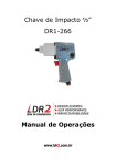
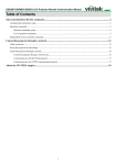
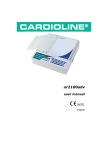
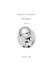
1
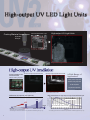
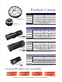
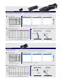
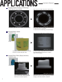
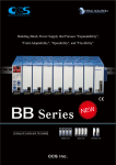
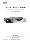
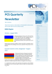
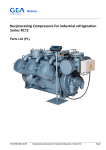
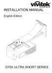
UV2 Series of High-output UV LED Light Units CCS Inc. High-output UV LED Light Units Coating Material Inspections High-output UV Light Units Normal Fluorescent Light Application Example Only the coating material on the board is captured. Image Comparison with Previous Models Previous UV Light Unit (LDR2-90UV365) High-output UV Light Unit(LDR2-100UV2-365-W) Adhesive Coating Inspection A Wide Range of Applications Grease presence inspections Adhesive coating inspections ITO film inspections Flux presence inspections And Many More Workpiece: Circuit Boards The High-output UV Light Unit has sufficient output for fluorescent observation. Insufficient output from the previous model makes fluorescent observation difficult. Differences in Output by UV Light Unit LWD Characteristics for High-output UV Light Units and Black Lights x150 x25 Output x1 UV Series UV2 Series LNSP-UV Series High * Comparison for Bar Lights/Irradiators. * The values given here are for reference only. Results for individual Lights may vary. 1 Relative output (%) Fluorescent Observation 100 90 80 70 60 50 40 30 20 10 0 LDR2-100UV2-365-W Normal black light (reference data) 10 20 30 40 50 60 70 80 90 100 110 120 130 140 150 LWD (mm) * The values given here are for reference only. Results for individual Light Units may vary. Products Lineup Ring Lights Model LDR2-60UV2-365-W Direct number 1006800 365 nm Peak wavelength (typ.) Input voltage (max.) OD: 100 mm 24 VDC Power consumption (max.) LDR2-100UV2-365-W Dimensions (mm) 7.6 W 23 W OD: 60, ID: 30, H: 30 OD: 100, ID: 30, H: 15 170 250 Weight (max. g) Applicable Control Units OD: 60 mm LDR2-100UV2-365-W 1006799 PD3 Series, PD2 Series, PSB Series, and BB Series, CC-ST-1024 (LDR2-60UV2-365 only) * These Light Units cannot be used with CCS Strobe Control Units with Overdrives. * For details on the applicable Control Units, refer to the general catalog or the CCS website. LDR2-60UV2-365-W Bar Lights Model Direct number LDL-71X12UV2-365 LDL-138X12UV2-365 LDL-205X12UV2-365 1006801 1006803 1006805 Peak wavelength (typ.) 365 nm Input voltage (max.) LDL Series Emitting surface 71×12mm 138×12mm 205×12mm 24 VDC Power consumption (max.) 7.6 W 16 W 23 W Emitting surface dimensions (mm) 71x12 138x12 205x12 300 500 700 Weight (max. g) Applicable Control Units PD3 Series, PD2 Series, PSB Series, and BB Series, CC-ST-1024 (LDL-71X12UV2-365 only) * These Light Units cannot be used with CCS Strobe Light Control Units with Overdrives. * For details on the applicable Control Units, refer to the general catalog or the CCS website. Condensing Models Model Direct number LN-61UV2-365 LN-128UV2-365 LN-195UV2-365 1006802 1006804 1006806 Peak wavelength (typ.) 365 nm Input voltage (max.) Light-condensing Models Emitting surface 61×16mm 128×16mm 195×16mm 7.6 W 16 W 23 W Emitting surface dimensions (mm) 61x16 128x16 195x16 450 750 1050 Weight (max. g) LN Series 24 VDC Power consumption (max.) Applicable Control Units PD3 Series, PD2 Series, PSB Series, and BB Series, CC-ST-1024 (LN-61UV2-365 only) * These Light Units cannot be used with CCS Strobe Light Control Units with Overdrives. * For details on the applicable Control Units, refer to the general catalog or the CCS website. Spotlights Model 1006798 Peak wavelength (typ.) 365 nm Input current (max.) 0.7 A Power consumption (max.) 3.2 W Dimensions (mm) OD: 28 (lens), ID: 24 (mounting hole), H: 54 Weight (max. g) HLV2-24UV2-365 Emitting surface HLV2-24UV2-365 Direct number Applicable Control Units 18 mm 50 PJ Series, CC-PJ-0707, and PD3 Series (HLV2 Series-compatible models) * These Spotlights cannot be used with CCS Strobe Light Control Units with Overdrives. * For details on the applicable Control Units, refer to the general catalog or the CCS website. Custom Products are Available Dimensions Shapes Higher Output Connectors Wavelengths (385 nm) Condensing Location Strobe Mounting Holes And Much More Contact your CCS representative for more details. 2 Technical Information for High-output UV LED Light Units Ring Lights LDR2-60UV2-365-W Model Used: LDR2-60UV2-365-W * The values given here are for reference only. Results for individual Lights may vary. LWD=30 mm LWD=50 mm (mm) (mm) 100 90 -100 -100 -100 -80 -80 -80 80 -60 -60 -60 70 -40 -40 -40 60 -20 -20 -20 50 0 0 0 40 20 20 20 30 40 40 40 20 60 60 60 10 0 10 20 30 40 50 60 70 80 90 100 110 120 130 140 150 -125 -100 -75 -50 -25 LWD (mm) 0 25 50 80 100 75 100 125 -125 -100 -75 -50 -25 (mm) * Simulation values. (These values are for reference only.) 100 90 80 70 60 50 40 30 20 10 0 0 25 50 80 100 75 100 125 -125 -100 -75 -50 -25 (mm) 0 LWD 0 10 20 30 40 50 60 Time (minutes) 70 80 LED Light Unit LWD 90 100 LDL-71X12UV2-365 LWD Characteristic 0 (mm) LDL-138X12UV2-365 -100 LDL-205X12UV2-365 * The values given here are for reference nce only. Results for individual Lights may vary. Uniformity LWD=50 mm LWD=100 mm LWD=150 mm (mm) (mm) (mm) 100 90 -100 -100 -100 -80 -80 -80 80 -60 -60 -60 70 -40 -40 -40 60 -20 -20 -20 50 0 0 0 40 20 20 20 30 40 40 40 20 60 60 60 10 0 10 20 30 40 50 60 70 80 90 100 110 120 130 140 150 -125 -100 -75 -50 -25 LWD (mm) 0 25 50 80 100 75 100 125 -125 -100 -75 -50 -25 (mm) * Simulation values. (These values are for reference only.) 0 25 50 80 100 75 100 125 -125 -100 -75 -50 -25 (mm) 0 25 50 80 100 75 100 125 Visualization of LWD Characteristic and Uniformity Measurement LED Light Unit Uniformity LED Light Unit LWD LWD 10 20 30 40 50 0 (mm) LWD Characteristic 0 100 * Simulation values. (These values are for reference only.) Output Changes Over Time 100 90 80 70 60 50 40 30 20 10 0 0 Uniformity LED Light Unit Model Used: LDL-205X12UV2-365 Relative irradiation strength (%) 80 100 75 100 125 Visualization of LWD Characteristic and Uniformity Measurement LWD Characteristic Bar Lights Relative output (%) 50 (mm) * Actual measurement values. (These values are for reference only.) 60 70 80 Time (minutes) 90 100 45° 110 120 * Actual measurement values. (These values are for reference only.) 3 25 100 * Simulation values. (These values are for reference only.) Output Changes Over Time Relative output (%) LWD=40 mm (mm) Output level (%) Uniformity Output level (%) Relative irradiation strength (%) LWD Characteristic LDR2-100UV2-365-W 100 0 (mm) -100 LN-61UV2-365 Model Used: LN-195UV2-365 Uniformity LWD=50 mm LWD=100 mm LWD=150 mm (mm) (mm) (mm) 100 90 -100 -100 -100 -80 -80 -80 80 -60 -60 -60 70 -40 -40 -40 60 -20 -20 -20 50 0 0 0 40 20 20 20 30 40 40 40 20 60 60 60 10 0 10 20 30 40 50 60 70 80 90 100 110 120 130 140 150 -125 -100 -75 -50 -25 LWD (mm) 0 25 50 80 100 75 100 125 -125 -100 -75 -50 -25 (mm) * Simulation values. (These values are for reference only.) 25 50 0 80 100 75 100 125 Visualization of LWD Characteristic and Uniformity Measurement LWD Characteristic Uniformity LED Light Unit LED Light Unit LWD LWD 0 10 20 30 40 50 60 70 80 Time (minutes) 90 100 45° 110 120 100 0 (mm) -100 HLV2-24UV2-365 HLV2-24UV2-365 * The values given here are for refere reference only. Results for individual Lights may vary. LWD Characteristic Uniformity LWD=10 mm LWD=30 mm LWD=50 mm (mm) (mm) (mm) 100 90 -50 -50 -50 -40 -40 -40 80 -30 -30 -30 70 -20 -20 -20 60 -10 -10 -10 50 0 0 0 40 10 10 10 30 20 20 20 20 30 30 30 10 40 50 40 50 40 50 40 50 0 10 20 30 40 50 60 70 80 90 100 110 120 130 140 150 -50 -40 -30 -20 -10 LWD (mm) 0 10 20 30 (mm) * Simulation values. (These values are for reference only.) -50 -40 -30 -20 -10 0 10 20 30 -50 -40 -30 -20 -10 (mm) 0 10 20 30 40 50 40 50 100 0 (mm) * Simulation values. (These values are for reference only.) Output Changes Over Time 100 90 80 70 60 50 40 30 20 10 0 0 * Simulation values. (These values are for reference only.) Spotlights Relative irradiation strength (%) 50 (mm) * Actual measurement values. (These values are for reference only.) Relative output (%) 25 100 Output level (%) 100 90 80 70 60 50 40 30 20 10 0 0 80 100 75 100 125 -125 -100 -75 -50 -25 (mm) Output Changes Over Time Relative output (%) LN-195UV2-365 * The values given here are for reference only. Results for individual Lights may vary. LWD Characteristic Relative irradiation strength (%) LN-128UV2-365 Output level (%) Condensing Bar Lights Visualization of LWD Characteristic and Uniformity Measurement LWD Characteristic Uniformity LED Light Unit LED Light Unit LWD LWD 0 10 20 30 40 50 60 Time (minutes) 70 80 * Actual measurement values. (These values are for reference only.) 45° 90 50 0 (mm) -50 4 Application Examples Imaging Grease Coating on Bearings White Light Unit (LDR2-90SW2) High-output UV Light Unit (LDR2-100UV2-365) The White Light Unit cannot capture only the grease. With a High-output UV Light Unit, fluorescent light is dispersed only by the grease. An optional Filter enables high-contrast imaging. (Filter used: L42 Series) Imaging Bottle Labels High-output UV Light Unit (LN-128UV2-365) Workpiece Image Enlargement Bottle (Filter used: L42 Series) The bottle and label are the same color, making it difficult to visually distinguish them. Fluorescent light is dispersed only by the label. The bottle absorbs UV lightwaves, enabling high-contrast imaging. Imaging Resin Parts (Spray Nozzles) Workpiece Image High-output UV Light Unit (LDR2-100UV2-365) Under a Fluorescent Light Spray Can (Filter used: L42 Series) It is not possible to capture only the spray nozzle under a fluorescent light. Part of the can is also captured. 5 With a High-output UV Light Unit, fluorescent light is dispersed only by the spray nozzle. High-contrast imaging of the resin surface is achieved. Dimension Diagrams (Unit: mm) Ring Lights LDR2-100UV2-365 300 (3.5 dia.) 300 30 45° 45° Four, M3 holes, Depth: 4 (for installation) 15 Four, M3 holes, Depth: 4 (for installation) 70 d ia. 100 dia. Ø3 Ø30 0 60 dia. 50 d ia. (3.5 dia.) LDR2-60UV2-365 Bar Lights All Models C 12 (emitting surface) B (emitting surface) 15 6 (45.6) Same a surface A 42 6 28 (3.5 dia.) 9 Surface A Ten, M3 holes, Depth: 6 (for installation) 300 20 24 11 9 Model E 30 D Light-condensing Models All Models D E LDL-71X12UV2-365 B (emitting surface) C (overall length) 71 91 P30x2=60 10 LDL-138X12UV2-365 138 158 P30x4=120 10 LDL-205X12UV2-365 205 225 P30x6=180 20 C B (emitting surface) 11 14 16 (emitting surface) Four, M3 holes, Depth: 6 (for installation) (47.6) 44 Same a surface A 6 (3.5 dia.) 9 47.5 Surface A Fourteen, M3 holes, Depth: 6 (for installation) 300 24 12 20 10 Model E 30 D Four, M3 holes, Depth: 6 (for installation) D E LN-61UV2-365 B (emitting surface) C (overall length) 61 91 P30x2=60 10 LN-128UV2-365 128 158 P30x4=120 10 LN-195UV2-365 195 225 P30x6=180 20 Spotlights HLV2-24UV2-365 54 (34) 24 dia. 18 Two, M3 holes (for installation) 28 dia. 13.2 300 (4.5 dia.) 18 dia. (emitting surface) 6 Common Specifications Input voltage 24 VDC (max.) Operating environment Temperature: 0 to 40°C, Humidity: 20% to 85% RH (with no condensation) Storage environment Temperature: −20 to 60°C, Humidity: 20% to 85% RH (with no condensation) Spectral distribution Orders are accepted for custom Light Units with a peak wavelength of 385 nm. Relative energy (%) Relative energy (%) Standard: 365 nm 100 90 80 70 60 50 40 30 20 10 0 345 355 365 375 385 395 405 415 Conforms to safety standard EN 62471. RoHS compliant Natural air cooling CE Marking Environmental regulations Cooling method 425 435 100 90 80 70 60 50 40 30 20 10 0 345 355 365 375 Wavelength (nm) 385 395 405 415 425 435 Wavelength (nm) * The values given here are for reference only. Results for individual Light Units may vary. Optional UV Products Cuts wavelength of 420 nm and lower and passes longer wavelengths. Ultraviolet Transmission Filters Ultraviolet Cutting Filters L42 U340 Series Series Spectral Distribution 365-nm UV LED 100 Transmittance (%) Passes UV lightwaves and absorbs visible light. Filter Characteristics vs UV LED Spectral Distribution 80 L-42 Filter 60 40 U-340 Filter 20 0 300 400 500 600 700 800 Wavelength (nm) Application Example (Shrink Film) Model Model Size Size U340-25 M25.5 P0.5 L42-25 M25.5 P0.5 U340-27 M27.0 P0.5 L42-27 M27.0 P0.5 U340-30 M30.5 P0.5 L42-30 M30.5 P0.5 U340-40 M40.5 P0.5 L42-40 M40.5 P0.5 U340-46 M46.0 P0.75 L42-46 M46.0 P0.75 Use a Filter that is suitable to the excitation wavelength. Consult your CCS representative. Blocks ambient light out of blue wavelength range. Blocks ambient light out of red wavelength range. Blue-light Filters V44 Sharp Cut Filters R60 Series Series Without Filter With Ultraviolet Cutting Filter Other Filters Yellow-light Filters* And Many More R64 Series * A special order is required. For details, please consult your CCS representative. Precautions for UV Products Caution Never look directly at or touch an ultraviolet light source. When the Light Unit is ON, always wear protective UV glasses and be sure not to let any ultraviolet light enter your eyes. Do not look at the radiating surface of the Light Unit directly while it is turned on. Also, do not turn it towards others. Example: Protective UV glasses Wear long sleeves and gloves and do not expose your skin to the ultraviolet light during operation. Make sure that everyone in the vicinity of the Light Unit is aware of the dangers of ultraviolet light LEDs. CCS, LIGHTING SOLUTION, LDR, LDL, HLV, LNSP, and HLUV are registered trademarks or trademarks of CCS Inc. Caution Carefully read the User Manual before using the product to ensure correct operation. For product improvement, specifications and designs are subject to change without notice. Use the workpiece imaging examples provided in this pamphlet as reference material for the selection of Light Units. The sample workpieces used in this pamphlet have been processed specifically for sample imaging. They are not intended to represent product quality and performance. CCS Inc. Headquarters CCS America, Inc CCS Europe NV/SA Shimodachiuri-agaru, karasuma-dori, kamigyo-ku, Kyoto 602-8011 JAPAN TEL : +81-75-415-8284 / FAX : +81-75-415-8278 URL : http://www.ccs-grp.com/ E-mail : [email protected] 5 Burlington Woods Suite 204 Burlington, MA 01803 USA TEL : +1-781-272-6900 / FAX : +1-781-272-6902 URL : http://www.ccsamerica.com/ Email : [email protected] Bergensesteenweg 423, Bus 13 1600 Sint-Pieters-Leeuw, Belgium TEL : +32-(0)2-333-0080 / FAX : +32-(0)2-333-0081 Email : [email protected] CCS Asia PTE LTD CCS Inc. Shanghai Office CCS Inc. Shenzhen office 63 Hillview Avenue #07-10, Lam Soon Industrial Building, Singapore 669569 TEL : +65-6769-1669 / FAX : +65-6769-3422 URL : http://www.ccs-asia.com.sg/ Email : [email protected] Room 308B-309, CIMIC Tower No.1090 Century Avenue, Pu Dong New Area, Shanghai 200120, P.R. China TEL : +86-21-5835-8728 / FAX : +86-21-5835-8928 Email : [email protected] 17B,China Economic Trade Building, 7Rd Zizhu, Zhuzilin, Futian District, Shenzhen 518040 P.R.China TEL : +86-755-8279-0477 / FAX : +86-755-8279-0478 Email : [email protected] Copyright © 2013 CCS Inc. All Rights Reserved. Content current as of August 2013 02002-00-1308-UV2