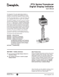
1
Building Block Power Supply that Pursues "Expandability",
"Field Adaptability", "Operability", and "Flexibility"
Lineup of 3 units and 10 models
Master unit
CC S I n c .
Slave unit
Interface unit
Adopting the building block system realizes
Building block system: A method of configuring a system in the same manner as piling up blocks through the selection and combination of units.
L i n eu p in t r o d u ct i on
Slave unit
M a s te r uni t
Interface unit
Unit designed for
expanding lights.
This can be added
and connected
depending on the
number of lights
you use.
Constant lighting
and strobe lighting
types are available.
Yo u c a n c h o o s e
from either 12V or
24V output types
depending on the
type of lighting to
be connected.
Unit provided with
setting and control
functions.
This controls all
connected units.
Constant lighting
and strobe lighting
types are available.
Yo u c a n c h o o s e
from either 12V or
24V output types
depending on the
type of lighting to
be connected.
Model name
Unit for external
control provided
with a parallel
communication
function.
CMOS input and
photocoupler
input types are
available.
Model name
Constant
lighting
12V
24V
BB-V12 P30-M
BB-V24P30-M
Strobe
lighting
12V
BB-V12 S30-M
24V
BB-V24S30-M
Constant
lighting
12V
BB-V12P30-S
24V
BB-V24P30-S
Strobe
lighting
12V
BB-V12S30-S
24V
BB-V24S30-S
Model name
CMOS
BB-CPC-S
Photo
coupler
BB-CPP-S
Description of model names
Master unit / Slave unit
Interface unit
BB-V
301
1 Output type
1)
2
2 Lighting type
3
2)
3 Unit type
1 2
12V output
P
Constant lighting M
2 4
24V output
S
Strobe lighting
S
-S
BB-CP
4
4 Parallel communication input type
Master
C
CMOS input
Slave
P
Photocoupler input
3)
*1) Our LED light is available in 12V input and 24V input types. Please select either of these types depending on the type of light you intend to use.
*2) The constant lighting type enables the setting of intensity in 256 steps (light control) through PWM (Pulse Width Modulation) control. The strobe lighting type is specified for overdrive, and can be set to lighting
times ranging from 0.001 to 1ms.
*3) The CMOS input type performs external control input and output using CMOSs in the same manner as our PD2 series digital power supplies. The photocoupler input type performs external control input and output
using photocouplers.
Expandability
1
Lineup of 3 units and 10 models
Realizes a wide variety of system configurations through the selection and combination of units
・Lineup of 3 master, slave, and interface units, and 10 models.
2 Easy addition and expansion of functions
・Comprehensive lighting control systems with multiple functions can be configured by adding units.
3 Units with different specifications can be integrated by a master unit
・You can choose either constant lighting or strobe lighting types for master and slave units.
(A maximum of 18 units can be connected: 1 master unit, 15 slave units, and 2 interface units)
1
4
Flexibly corresponds to changes of inspection environments through the addition of slave units
5
Controls more than one lighting unit through interface units
・The addition of lights due to changes of inspection environments can be flexibly handled through the addition of slave units.
・Interface units (parallel communication function) can be selected from either CMOS input or photo-coupler input types.
(A maximum of eight slave units can be controlled through communication.)
optimum light control environments.
Field adaptability
1
Adaptable to field environments
DIN rail mounting suitable for installation environments
・Can be installed on DIN rails in a single operation without the need for screws or
tools.
2 DC24V input specification suitable for power source environments
・Control operations can be integrated with DC24V inputs in common with machine
vision equipment.
3 Simple wiring and easy maintenance
・Can be connected to interface units (parallel communication function) through a
single cable. Also connected to other units via the coupling connector of the main
body, which eliminates extra wiring.
4
5
Space-saving compact design
・Compact bodies has realized weight reductions. In addition, a compact design
contributes to space-saving installation.
Unified design and size
・Unification of design and body size with other units improves operability and maintenance
performance.
O p e r a b i l ity
1
Easy operation enables smooth working on site.
Centralized control by a master unit
・A wide variety of setting and control functions are integrated into the master unit. Connected units can be
identitied by ID numbers.
2 One-touch operation
・Units can be operated using panel buttons. Reliable setting using one-touch operation has improved
operability.
3 Improved reproducibility and visibility
・Digital displays provide clear readings at a glance. Operation conditions can be checked and setting
values can be controlled easily.
4
5
Set-data Protection
・A locking function is employed in order to prevent set values from being change. Data is reliably protected
allowing for the maintenance only by authorized operators.
Error display function
・When any errors occur, details are displayed on the display panel, allowing for the early implementation
of countermeasures.
Flexibility
1
Operation function can be selected to suit specific environments.
Flexible selection of operation functions
・The lighting mode can be selected and the lighting frequency and signal logic can be changed for the
constant lighting type.
・Pulse width and delay time can be set and signal logic can be changed for the strobe lighting type.
2
Expandability
A wide variety of system configurations
Lineup of 3 units and 10 models
Slave unit
Mast er uni t
Type 1
Interface unit
Type 1
12V output and
constant lighting
Type 1
12V output and
constant lighting
Type 2
CMOS input
Type 2
24V output and
constant lighting
Type 2
24V output and
constant lighting
Lineup of 3 units and 10 models.
Type 3
Photocoupler input
Type 3
12V output and
strobe lighting
12V output and
strobe lighting
Type 4
Type 4
24V output and
strobe lighting
24V output and
strobe lighting
Select one from four types.
Select required quantities.
Select when using external control.
Combination
example
Type 1
Type 1
Type 4
Type 1
12V output and constant lighting
24V output and strobe lighting
12V output and constant lighting
CMOS input
Combining units for a comprehensive multi-function lighting control system
System configuration image
Type 1
12V output and
constant lighting
Type 4
24V output and
strobe lighting
Functions can be added
and expanded by coupling
a slave unit.
Type 1
CMOS input
A single master unit
can be used.
External communication
is carried out via a single
interface unit.
One master unit
Two interface units
A maximum of 18 units can be coupled.
Units with different specifications can
also be coupled.
This allows for the configuration of
large-scale lighting control systems.
3
Fifteen slave units
Examples of system configurations
Constant lighting and strobe lighting types are combined for the inspection of many items.
Example 1
Three items
are inspected
at the same
time.
24V output
Constant
lighting type
12V output
Constant
lighting type
12V output
Strobe
lighting type
Cap printing inspection
12V output
Constant
lighting type
Example 2
Simultaneous
inspection
of three lines.
12V output
Strobe
lighting type
12V output
Strobe
lighting type
Liquid level inspection
Two-dimensional code
reading inspection
Dimension inspection
Foreign substance mixing inspection
Printing inspection
Different combinations of units enable the flexible handling of a wide variety of inspection items.
Example 3
Composite
inspections by
changeover
24V output
Constant
lighting type
24V output
Strobe
lighting type
24V output
Constant
lighting type
Up to 15 units are controlled
i n t e g r a l l y.
A single master unit enables the integrated
24V output
Strobe
lighting type
control of up to 15 slave units.
12V output
Constant
lighting type
One master unit
Appearance inspection
Printing inspection
15 slave units
Controls more than one lighting unit by external controller through the interface unit.
Example 4
Externally
controls
simultaneous
inspections.
24V output
Constant
lighting type
24V output
Constant
lighting type
interface unit
Up to 8 units are controlled by one
interface-unit.
One interface unit controls up to eight units
Letter inspection
Lighting in red
Connected to external
equipment such as PLCs.
through communication.
One master unit
One interface unit
Letter inspection
Lighting in blue
7 slave units
4
Field adaptability
DIN rail mounting suitable for installation environments
Easy mounting
No screw
No tools!!
Optional stand is available.
Adaptable to field environments.
Compatible with installation environments
other than DIN rails.
One push
When mounting the unit
Stand
When removing
Engage the
upper tab.
Side of DIN rail
Engage with
the hole, and
push down.
Slot-head screwdriver
or other tool
Installation into control box.
※Image of installation into a control box
Master unit
Interface unit
DC24V input specification
External control can be
connected using a single cable.
Power is supplied through
a coupled connector.
Slave unit
Power can be supplied
by connecting wiring.
Unit can be connected in a single operation.
Connecting parts
Top
Just insert into the coupling connector.
Coupling
connector
Terminal unit
Plug the Terminal Unit
into the unit currently at
the end of the series.
(Attached to the master unit)
Terminal unit
Bottom
Connecting parts
※ Fix the top and bottom with the
attached connecting parts.
※Caution
Make sure that the power is turned off before connecting or separating the unit.Connecting or separating the unit with the power ON may damage the system.
5
Compact design (*compared with our conventional products)
Approx.
40
350g
148
Weight reductions attained through
the employment of compact bodies.
2 - 3 012 / 3 0 2
PD
4
Approx.
1,000g
62
110
BB power supply series
・Master unit
Appoximately 400g
・Slave unit
Appoximately 400g
・Interface unit
Appoximately 300g
Digital power supply series
・Strobe power supply
PTU2-3012 / 3024
Appoximately 1,200g
The weights of units have been drastically
reduced in comparison with conventional
units.
Units can be carried and installed easily.
Slimlining has been realized
through compact designs.
As the width of the units is 40mm, even
when multiple units are connected they
can be operated and controlled in small
spaces.
Unified design and size
The design and size of the unit
bodies have been unified.
The unified design and size has been
employed to realize building block concept
for easy installation.The unified design and
size of unit bodies allows for adaptation
to installation environments.
Operability and visibility have
been i mproved.
The employment of panel buttons and
digital display panels has improved
operability , increased reproducibility
and visibility.
6
Operability
Central operation by master unit
A wide range of settings and control functions
Digital display panel
LED lamp
LED lamp indicates a function that can
be selected.
(Selected function flashes on the display)
Front
Ease of use enables smooth working on site.
Ch : For selecting channels
Brt : For setting light control data
(constant lighting type only)
Pls : For setting the pulse width
Dly : For setting the delay time
(strobe type only)
Opt : For setting optional functions
Terminal unit
The Terminal Unit is inserted at the rear
end of the unit.
※Caution
Do not remove the Terminal Unit while the power is turned
on. Doing so may damage the system.
Panel buttons
Output connector
The unit can be operated by the panel
buttons. Reliable one-touch settings
improvs operability.
Employs a connector with a new configuration.
Used for connections with lighting units via the
dedicated cable included. Two types are
available for 12V and 24V lighting.
…Select button
SEL
Select the function desired to be set.
Output connector
Pin configuration
B1
…Numerical value setting buttons
(up/down buttons)
B2
B3
Pin number
…Range button
RANG
Shifts the digits of numerical values.
…Enter/lock button
ENT/
LOCK
Confirms a function or numerical value.
When this button is pressed and held down,
it is locked, and when it is held down again,
lock is released.
A1
A2
A3
Description
A1
L ED I D
A2
Nothing to be
connected
A3
Nothing to be
connected
B1
Output+24V
B2
Output+12V
B3
COM
Items included
Terminal configuration
•Intermediate cable for 12V lighting for
12V output units.
•Intermediate cable for 24V lighting for
24V output units.
Equipped with a DC24V input terminal,
a trigger signal input terminal, and an
FG terminal.
Terminal block
TRIG+
24V+
4
1
24Vー
5
2
ー
TRIGー
6
3
Bottom
FG
ID setting switch
All the units can be registered by ID numbers.
Pin configuration
Pin number
Description
1
24V+
2
24Vー
3
FG
4
TRIG+
5
TRIG ー
6
Nothing to be
connected
Recommended crimp terminal : NICHIFU M3 crimp
terminals with insulating sheath Ring or “Y” TMEV
1.25-3
Mounting screw hole for mounting to stand.
Used for mounting the unit instead of
DIN rails.
Also used for mounting to the optional
stand.
Mounting screw hole for connecting parts.
Use the attached connecting parts when
fixing units.
※ See the User Manual for details related to each item.
7
Operation conditions can be checked and
set values can be controlled easily.
Also equipped with an error display function
that notifies the user by error code when any
errors occur.
ON
1
2
3
4
Switch positions for setting ID numbers
No. 0
No. 4
No. 8
No. 12
No. 1
No. 5
No. 9
No. 13
No. 2
No. 6
No. 10
No. 14
No. 3
No. 7
No. 11
No. 15
※Caution
Make sure that the power is turned off before setting
ID numbers.
Setting numbers with the power ON may damage the
system.
Points when setting ID numbers
ID numbers at the time of shipment are set
at 0 for all units.
When adding a unit, set the master unit at
ID No.0, and set the other units at ID No.1,
2,3 etc. in the order of coupling, in order to
allow for easy operation and control.
Flexibility
Customization is possible using the optional functions of units.
Constant lighting type
Operation function can be selected to suit specific environment.
・ Lighting modes can be selected from three modes, i.e., constant lighting,
ON/OFF mode (*1), and trigger mode (*2).
・ Lighting frequencies can be selected from 62.5, 125, 250, and 500kHz.
・ The logic of the signal to be used can be selected.
(Turns on at active high/active low.)
*1) Light on and off controlled by ON/OFF signal
*2) Pulse lighting controlled by trigger signal.
Strobe lighting type
・Pulse width can be set in the range from 0.001 to 1ms.
・Delay time can be set in the range from 1 to 1,000μs.
・The logic of the signal to be used can be selected.
(Turns on at active high/active low.)
From your current power supply to the BB power supply
Application example
1
2
3
4
5
6
・Uses one digital power supply.
・Uses one 12/24V LED light when using
constant lighting.
・One channel with a capacity of 30W
・Uses one strobe light power supply.
・Uses one 12/24V LED light when using
strobe lighting.
・Two channels with a total capacity of 30W (PTU2 Series only)
・Uses two digital power supplies.
・Uses two 12/24V LED lights when using
constant lighting.
・One channel with a capacity of 30W
・Uses two strobe light power supplies.
・Uses two 12/24V LED lights when strobe
lighting.
・2 channels with a total capacity of 30W (PTU2 Series only)
・Uses LED light through external control.
・Used in parallel communication systems.
・CMOS type input signal.
・Uses LED light through external control.
・Used in parallel communication systems.
・Photocoupler type input signal.
Your current power supply type
Digital power supply
• P D 2 - 3 012
•PD2-3024
Strobe light power supply
• P T U 2 - 3 012
•PTU2-3024
Digital power supply
• P D 2 - 3 012
•PD2-3024
Strobe light power supply
• P T U 2 - 3 012
•PTU2-3024
Digital power supply/Strobe light power supply
•PD2-3012/PD2-3024
•PTU2-3012/PTU2-3024
Digital power supply/Strobe light power supply
•PD2-3012/PTU2-3012
•PD2-3024/PTU2-3024
Corresponding BB series
BB power supply and
other functions
・1 channel
・ON/OFF control
・Pulse lighting
・Setting of frequency
・Selection of signal logic
・1 channel
・Setting of lighting delay
time
・Lighting test mode
・Selection of signal logic
• Ma s t e r u n it
+
• S la v e u n it
B B - V12 P 3 0 - S /
B B - V24 P 3 0 - S
・1 channel
・12/24V output
・30W capacity
・Constant lighting
・ON/OFF control
・Pulse lighting
・Frequency setting
・Selection of signal logic
• Ma s t e r u n it
+
• S la v e u n it
B B - V12 S 3 0 - S /
B B - V24 S 3 0 - S
・1 channel
・12/24V output
・30W capacity
・Strobe lighting
・Setting of lighting delay
time
・Lighting test mode
・Selection of signal logic
・Parallel
・Selection of signal logic
• Ma s t e r u n it
・12/24V output
B B - V12 P 3 0 - M / ・30W capacity
B B - V24 P 3 0 - M ・Constant lighting
• Ma s t e r u n it
・12/24V output
B B - V12 S 3 0 - M / ・30W capacity
B B - V24 S 3 0 - M ・Strobe lighting
• Ma s t e r u n it
communication
+
・CMOS input
• In t e r f a c e u n it ・Communication
BB -CPC-S
control of up to
eight units.
・Parallel
• Ma s t e r u n it
communication
+
• In t e r f a c e u n it ・Photocoupler input
BB -CPP-S
・Selection of signal logic
・Communication
control of up to
eight units.
8
Specifications
Products conforming to RoHS Directive.
Master unit / Slave unit
Product name
Model name
Master unit
BB-V12P30-M
BB-V24P30-M
BB-V12S30-M
BB-V24S30-M
Slave unit
BB-V12P30-S
BB-V24P30-S
BB-V12S30-S
BB-V24S30-S
Lighting system
Constant lighting
Strobe lighting
Drive method
Constant voltage
Light control method
PWM control
Pulse width
Channels
Applicable light (rating)
1 channel
12V/30W
24V/30W
Input voltage (rated)
Input voltage (range)
Power consumption (typ.)
12V/30W
24V/30W
DC21.6 ∼ 26.4V
DC21.6 ∼ 26.4V
DC24V
DC21.6 ∼ 26.4V
DC21.6 ∼ 25.3V
42W
42W
Mean power consumption:16W Mean power consumption:16W
(during connection to 30W load) (during connection to 30W load) (during connection to 30W load) (during connection to 30W load)
Peak power consumption:72W
(during connection to 30W
load and strobe)
Output voltage (rated)
DC12V
DC24V
Output current (rated)
2.5A
1.25A
DC18V
DC48V
8.0A
4.3A
Power code length
5m max.
Terminal block control cable length
5m max.
Light cable length
5m max.
Mounting method
On DIN rails, on bottom surface mounting hole/(Fixed using the optional self-support stand)
Operating temperature and humidity
Temperature : 0-40℃, Humidity : 20-85%RH (with no condensation)
Storage temperature and humidity
Temperature : -20-60℃, Humidity : 20-85%RH (with no condensation)
Weight
Product name
Model name
350g max.
350g max.
350g max.
400g max.
Interface unit (parallel communications)
BB-CPC-S
BB-CPP-S
Input voltage (rating)
DC24V(Supplied via coupled connector)
Input voltage (range)
DC21.6-26.4V(Supplied via coupled connector)
Power consumption (typ.)
10W(Supplied via coupled connector)
External control input/output
Parallel bit system
External control input
/output specifications
External control cable length
Use environment
Storage environment
Weight
9
Peak power consumption:26W
(during connection to 30W
load and strobe)
No insulation, C-MOS level input/output
LOW : 1.5V max., High : 3.5V min.
2.2k Ohms, 5V pull-up
Input voltage range : 0V-5.5V DC
Photocoupler insulation : 24V input/output
OFF : 10V max., ON : 14V min.
OFF current : 4mA max.,
ON current : 5.8mA min.
Input voltage range : 0V-26.4V DC
Less than or equal to 5m
Temperature : 0-40℃, Humidity : 20-85%RH (free from condensation)
Temperature : -20-60℃, Humidity : 20-85%RH (free from condensation)
300g max.
Dimensional diagrams (mm)
Master unit
B B - V1 2 P 3 0 - M / B B - V 2 4 P 3 0 - M
B B - V1 2 S 3 0 - M / B B - V 2 4 S 3 0 - M
115.5
40
12.5
34.5
148
52.6
22.7
BBV12P30-M
3.5
6.5
28.1
6
3-M3 depth 4 (anchoring screw hole)
27
Installation of DIN rail
26.5
26.5
26.5
36
115.5
40
4
72
DIN rail
Slave unit
76
148
B B - V1 2 P 3 0 - S / B B - V 2 4 P 3 0 - S
B B - V1 2 S 3 0 - S / B B - V 2 4 S 3 0 - S
115.5
40
12.5
34.5
148
52.6
22.7
BBV12P30-S
3.5
6.5
Connected assembly
3-M3 depth 4(anchoring screw hole)
27
Top view
26.5
26.5
40
40
40
6.5
4
27
13
27
6.5
36
Interface unit
115.5
25.5
26.5
26.6
26.5
Bottom view
40
BB-CPC-S
BB-CPP-S
115.5
12.5
PARALLEL
34.5
6.5
148
12.1
3.5
22.7
BB-CPP-S
52.6
40
27
3-M3 depth 4(anchoring screw hole)
26.5
26.5
26.5
36
10
Option
Stand
External control cable for parallel communication
Optional to be attached to the unit.
Use this when fixing the unit with something other than DIN
rail for desktop or floor-top use.
Cable for connecting interface units (parallel communication
type) and external equipment such as PLCs and image
processing units.
■ BB-FT
■ EXCB2-BBP-5
Pin assignment
Half pitch connector 50-pin
One-side bulk line
Notes:
Carefully read the product's instruction manual before use to ensure correct operation.
Product specifications and design are subject to change without notice.
Examples of workpiece imaging in this catalog are a guide that may be informative for choosing illuminations. Please check the functions of the equipment and
requirements when choosing.
Headquarters
Shimodachiuri-agaru, Karasuma-dori, Kamigyo-ku, Kyoto 602-8011 Japan
Phone: +81-75-415-8284 / Fax: +81-75-415-8278
URL: http://www.ccs-grp.com
E-mail: [email protected]
Copyright(c) 2008 CCS Inc. All Rights Reserved.
Description in this catalog are based on information available as of November 2008. 01002-01-0806-BB