1
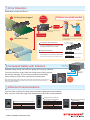
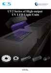
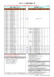
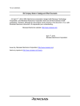
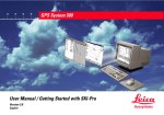
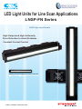
LED Light Units for Line Scan Applications
LNSP-FN Series
LNSP
LNSP High-output
High-output Models
Models
High Output and High Uniformity
Error Detection to Avoid Problems
Constant Current Control
Emitting Surface Lengths from 100 to 1,500 mm
W W W. S T E M M E R- I M A G I N G . C O M
CCS Inc.
LED Light Units for Line Scan Applications
LNSP-FN Series
LNSP High-output Models
Features
Applications
High-output Irradiation
Highly Uniform Irradiation Constant-current Control
Dark Field Applications
Error Detection (Control Unit)
▪ Cooling fan error detection
▪ LED open circuit and short circuit detection
Bright Field Applications
Illuminance: 900,000 lx
*LWD = 50 mm
Increase your inspection speed in line scan applications.
Illuminance (Ix)
Illuminance (LWD Characteristic)
1,200,000
1,100,000
1,000,000
900,000
800,000
700,000
600,000
500,000
400,000
300,000
200,000
100,000
0
* Actual measurement values at 100% intensity and the
specified radiated distances. Results may vary for
individual Units.
Image Comparison for Japanese Paper
LNSP
LNSP-FN
Ideal for applications
that require
high-speed image
processing.
LNSP-FN
Brightness
Increased!
LNSP
2
More than x
sensitivity
0
25
50
100
75
125
150
175
200
*Brightness will vary based on the camera’s spectral response.
LWD (mm)
High Uniformity
Luminance Distribution (Emitting Surface)
LED Light Unit used: LNSP-400SW-FN
*The data provided here is for reference only. Results for individual Units may vary.
Long Side Direction
Short Side Direction
Output of 90% or
higher for effective
emitting surface of
360 mm.
Relative luminance (%)
90
80
70
60
50
40
30
20
Output of 90% or
higher for approx.
8-mm width
90
80
70
60
50
40
30
20
10
10
0
100
Relative luminance (%)
100
-200 -180 -150
-100
-50
0
50
100
Position in the width direction (mm)
150 180 200
0
-10
-5 -4
0
4 5
10
Position in the width direction (mm)
Lineup with Light-emitting Surface Lengths from 100 mm to 1,500 mm
Specify the emitting surface length in 100-mm increments.
We provide you with the right length of Light Unit for your specific needs.
You can specify lengths in 100-mm
increments between 100 mm...
...and 1,500 mm.
You can order custom lights with emitting surface lengths up to 3,000 mm. For details, please contact a CCS sales office.
1
W W W. S T E M M E R- I M A G I N G . C O M
Error Detection
Notification of Light Unit Errors
!
Cooling fans stopped.
Problems are quickly avoided.
Error
detected!
*Visualization.
Error output.
PSCC- 60048
Control Unit for LED Light Unit
PSCC-60048
Error displayed
in digital display.
!
Error
discovered.
Warning lamp
turns ON.
*This visualization assumes that an error signal
is sent to a warning lamp that is connected to
turn ON the light.
LEDs fail to light.
Fan speed is checked.
Cooling Fan Error Detection
An error is detected in the rare event that
a cooling fan slows down or stops.
▪ All fans are monitored.
LED Error Detection
A burnt-out LED is detected if the lighting
circuit is open or the LED is short-circuited.
Open Circuit
The LED fails to light because the circuit is open.
Short Circuit
*Detection of short circuits depends on the detection condition.
Increased Safety with Interlock
The LED fails to light because it is broken.
Digital display
Maintain safety during work with the power OFF and key switches.
You can prevent the Light Units from being turned ON by anyone
but the key manager, or from being turned ON accidentally
when setting up Light Units or performing maintenance.
*Locking the light intensity is also possible when using parallel communications for external control.
*Refer to NTLPxREFERENCE PSCC-60048 Control Units for LED Light Units User Manual for
specific application information.
External control connector
Key lock
PSCC-60048
Control Unit
for LNSP-FN
Turn OFF
power and lock
the key during
work
procedures.
Ethernet Communications
You can build a Light Unit control system based on Ethernet communications.
Also, you can control the Light Units with parallel or EIA-485 communications.
Parallel Communications
Connection Specifications
Ethernet Communications Specifications
Rated input voltage
24 VDC
EIA-485 Communications
Specifications
Maximum input voltage
26.4 VDC
Protocol
EIA-485 compliant
Communications protocol TCP/IP UDP/IP
ON voltage/ON current
20 VDC min./6 mA min.
Baud rate
19200 bps
Standard
IEEE 802.3, 802.3u, 802.3x
OFF voltage/OFF current 3 VDC max./1 mA max.
Data bit length 8 bits
Baud rate
10 Mbps or 100 Mbps (Automatically detected.)
Response time
Approx. 100 ms
Parity bit
None
Transmission medium
10Base-T or 100Base-TX
Input impedance
6.8 kΩ (per terminal)
Stop bits
1 bit
*Refer to NTLPxREFERENCE PSCC-60048 Control Units for LED Light Units User Manual for specific application information.
2
W W W. S T E M M E R- I M A G I N G . C O M
LNSP-FN series
LNSP-FN Data
Illuminance Distribution Graph
LED Light Unit used: LNSP-400SW-FN
Measurement Directions
Long side
Short side
Light Working Distance: 50 mm
Measurement direction: Long side
Long Side Direction
100
90
80
Relative Illuminance (%)
LWD:
50 mm
70
60
50
40
30
20
10
LWD:
100 mm
0
−200
−150
−100
0
−50
50
100
150
200
Position in the width direction (mm)
*Actual measurement values at 100% intensity and light working distance of 50 mm. Results may vary for individual Units.
Light Working Distance: 100 mm
Measurement direction: Long side
Long Side Direction
100
Relative Illuminance (%)
90
LWD:
200 mm
80
70
60
50
40
30
20
10
0
−200
−150
−100
0
−50
50
100
150
200
Position in the width direction (mm)
*Actual measurement values at 100% intensity and light working distance of 100 mm. Results may vary for individual Units.
Light Working Distance: 200 mm
Measurement direction: Long side
Long Side Direction
100
Relative Illuminance (%)
90
80
70
60
50
40
30
20
10
0
−200
−150
−100
−50
0
50
100
150
200
Position in the width direction (mm)
*Actual measurement values at 100% intensity and light working distance of 200 mm. Results may vary for individual Units.
3
W W W. S T E M M E R- I M A G I N G . C O M
LED lighting for line sensors
LNSP-FN Data
Luminance Distribution (Emitting Surface)
LED Light Unit used: LNSP-400SW-FN
Measurement direction: Long side and short side
Short Side Direction
100
90
90
80
80
Relative luminance (%)
Relative luminance (%)
Long Side Direction
100
70
60
50
40
30
20
70
60
50
40
30
20
10
10
0
0
−200
−150
−100
0
−50
50
100
150
200
−10
0
−5
5
10
Position in the width direction (mm)
Position in the width direction (mm)
*The data provided here is for reference only. Results for individual Units may vary.
Illuminance Graph
Light Distribution Characteristics
LED Light Unit used: LNSP-1500SW-FN
Measurement direction: Short side
Relative Illumination Distribution
Illuminance (LWD Characteristic)
1,200,000
100
1,100,000
90
1,000,000
Relative illumination (%)
900,000
Illuminance (lx)
LED Light Unit used: LNSP-400SW-FN
800,000
700,000
600,000
500,000
400,000
300,000
200,000
80
70
60
50
40
30
20
10
100,000
0
−15
0
0
50
100
LWD (mm)
150
200
0
−5
10
15
*The data provided here is for reference only. Results for individual Units may vary.
LED Light Unit used: LNSP-1500SW-FN
Temperature Changes Over Time
Intensity Changes Over Time
LED Light Unit used: LNSP-1500SW-FN
Temperature Changes Over Time
80
120
100
Stable at approx.
43°C after 35 min
60
80
Variations: 3%
60
40
Temperature (°C)
Relative light output (%)
5
Angle (°)
*Actual measurement values at 100% intensity and the specified light working distances.
Results may vary for individual Units.
Intensity Changes over Time
−10
Housing temperature
40
20
Ambient air temperature
20
0
0
0
50
Time (minutes)
0
100
* Actual measurement values at 100% intensity, constant lighting, and an ambient air temperature of
25°C. Results may vary for individual Units.
Light Output Characteristics
LED Light Unit used: LNSP-1500SW-FN
30
60
Time (minutes)
90
120
*Actual measurement values at 100% intensity and constant lighting. Results may vary for individual Units.
LED Light Unit Cable Length vs. Output Characteristic
LED Light Unit used: LNSP-1500SW-FN
Output Characteristic
Intensity Control Characteristics
100
100
80
Relative light output (%)
Relative light output (%)
90
70
60
50
40
30
20
Output is also 100%
for 20-m Cable.
80
60
40
20
10
0
0
50
100
150
Intensity control setting (256 levels)
200
255
*Actual measurement values with a PSCC-60048 Analog Control Unit. Results may vary for individual Units.
0
0
2
3
5
10
Cable length (m)
20
*Actual measurement values at 100% intensity and constant lighting. Results may vary for individual Units.
4
W W W. S T E M M E R- I M A G I N G . C O M
LNSP-FN series
Specifications
Direct number
1600
LED color
Model
Light-emitting
surface length
Power consumption
(max., including fans)
LNSP-100SW-FN
100 mm
41 W
900 g
LNSP-200SW-FN
200 mm
81 W
1,400 g
LNSP-300SW-FN
300 mm
117 W
1,900 g
LNSP-400SW-FN
400 mm
157 W
2,400 g
LNSP-500SW-FN
500 mm
192 W
2,900 g
LNSP-600SW-FN
600 mm
233 W
3,400 g
LNSP-700SW-FN
700 mm
268 W
3,900 g
LNSP-800SW-FN
800 mm
309 W
4,400 g
LNSP-900SW-FN
900 mm
345 W
4,900 g
LNSP-1000SW-FN
1,000 mm
384 W
5,500 g
LNSP-1100SW-FN
1,100 mm
425 W
6,000 g
LNSP-1200SW-FN
1,200 mm
460 W
6,500 g
LNSP-1300SW-FN
1,300 mm
501 W
7,000 g
LNSP-1400SW-FN
1,400 mm
536 W
7,500 g
LNSP-1500SW-FN
1,500 mm
576 W
8,000 g
White (SW)
Case material
Acrylic, aluminum alloy, POM, and steel plates
Cable length
300 mm
Connectors
Metal Connector (PRC04-12A26S-37M18)
Operating environment
Temperature: 0 to 40°C, Humidity: 20% to 85% (with no condensation)
Storage environment
Temperature: −20 to 60°C, Humidity: 20% to 85% (with no condensation)
CE Marking
Weight
(max.)
5,800 K (typ.)
Correlated color temperature
Safety standards: Conforms to EN 62471, EMC standard: Conforms to EN61000-6-2 and EN 61000-6-4.
Environmental regulation
RoHS compliant
Cooling method
Forced air cooling
Frame nuts (four for emitting surface length up to 1,000 mm, seven for emitting surface length over 1,100 mm), one FG line (2 m), one set screw (M3)
Relative light output (%)
Accessories
Spectral distribution
100
90
80
70
60
50
40
30
20
10
0
300
380
460
540
620
700
780
860
Wavelength (nm)
n: Emitting surface length
1.5
19
Detail View A
56.5
0
30
32
(101.3)
14.5
(13.6 dia.)
12
34
62
(6.7)
4
41
n+44: Overall length
16
(ooo : Emitting surface length)
6
LNSP-oooSW-FN
23 (Light-emitting surface)
Dimension Diagram (mm)
Model
n
No. of
cooling fans
LNSP-100SW-FN
100
1
LNSP-200SW-FN
200
2
LNSP-300SW-FN
300
3
LNSP-400SW-FN
400
4
LNSP-500SW-FN
500
5
LNSP-600SW-FN
600
6
LNSP-700SW-FN
700
7
LNSP-800SW-FN
800
8
LNSP-900SW-FN
900
9
LNSP-1000SW-FN
1,000
10
LNSP-1100SW-FN
1,100
11
LNSP-1200SW-FN
1,200
12
LNSP-1300SW-FN
1,300
13
LNSP-1400SW-FN
1,400
14
LNSP-1500SW-FN
1,500
15
For mounting
Fan air inlets
2×M3
(To attach FG line, same on opposite side.)
Four nut slots
Detail View A
Options
LED Light Unit Cables
QCB Series
3000815
3000816
3000817
3000818
3000819
QCB-2
QCB-3
QCB-5
QCB-10
QCB-20
Cable length
2m
3m
5m
10 m
20 m
Weight (max.)
1.1 kg
1.5 kg
2.4 kg
4.6 kg
8.9 kg
Direct number
Model
These cables are used to connect LED Light Units to
Control Units.
Use the Cable that is suitable for your installation site.
Cable diameter: 16.5 mm
Allowable cable bending radius: 99 mm
5
W W W. S T E M M E R- I M A G I N G . C O M
LED lighting for line sensors
Control Units for LNSP-FN
Analog Control Unit for LED Light Unit: PSCC-60048
Features
Constant-current system.
Light intensity control to 256 levels.
1 channel/1 connector (37-pin metal connector)
Output: 582 W
Use Ethernet, parallel, or EIA-485 communications for external control.
External controls (Dimming control and ON/OFF control)
Error detection for cooling fan error, LED open circuit, LED short circuit, etc.
Interlock with key switch or external control via parallel communications
Specifications
Front View
Rear View
Dimension Diagram (mm)
Model
PSCC-60048
Direct number
2000846
Lighting method
Constant lighting
Drive method
Constant-current system
Manual/external
Setting switch mode selector Ethernet
communications
connector
Digital display
Light control method Variable current control
Number of channels 1 channel
Applicable Light Units (rated)
43 VDC max., 582 W max. (including 30 W max. for fans)
Light intensity control
Manual and external intensity control
225
371
Front manual/external switch (MODE)
P S C C - 60048
Manual Set any of 256 levels via the setting switch. Press and hold the switch for 2 seconds to lock the intensity value.
Parallel communications
8-bit intensity value setting (B0 to B7) and write signal (WR)
EIA-485 communications
Command input through EIA-485 communications
Ethernet communications
Command input via TCP/IP or UDP/IP communications
INTENSITY
131
External
Air inlet
External control mode can be selected by pushing the setting switch while turning ON the power to the Control Unit.
Lighting control
Parallel bit input
OFF signal (ON/OFF)
EIA-485 communications
Command input through EIA-485 communications
Key lock
ON/OFF input
connector
Ethernet communications
Command input via TCP/IP or UDP/IP communications
EIA-485 communications
settings
ID
Set via the front ID switch (00 to 03). Maximum of 4 connected Units.
Error detection
display
LED burnout detection, open circuit Front digital “E01” display
Set via the front ID switch. (Terminating resistance is connected only when ID is set to 00.)
Terminating resistance
EIA-485 communications connector
LED burnout detection, short circuit Front digital “E02” display
Light Unit fan slowdown or stoppage
Front-panel digital “F01” to “F15” display
Output connector
(37-pin metal connector)
Communications error detection Front digital “E04” display
Connector unconnected detection Front digital “E04” display
Fan exhaust outlet
Internal Control Unit error detection Front digital “E05” display
Error detection
output
ID switch
Parallel
communications connector
Parallel communications
Four, M4 bottom mounting screws
(Insertion depth of 5 mm max.)
Output to pins 19 and 20. Photocoupler isolation. Open-collector output. Closed for alarm (Load current: 10 mA max.)
EIA-485 communications Confirmed with status command via EIA-485 communications. (Command sent at error occurrence.)
100 to 240 VAC (+10%, −15%), 50/60 Hz
Power consumption (typical)
750 VA
192
Ethernet communications Confirmed with status command via TCP/IP or UDP/IP communications. (Command sent at error occurrence.)
Input power
POWER
Storage temperature and humidity
Temperature: −20 to 60°C, Humidity: 20% to 85% RH (with no condensation)
Cooling method
Forced air cooling
CE Marking
Safety standard: Conforms to EN 61010-1, EMC standard: Conforms to EN 61326-1, Class A.
Environmental regulation
RoHS compliant
Power switch
16.5
Operating temperature and humidity Temperature: 0 to 40°C, Humidity: 20% to 85% RH (with no condensation)
AC inlet
18
335
Material, coating, and surface processing Steel plate, thickness of cover: 1.0, thickness of chassis: 2.0, N3 leather tone finish
Weight
7,000 g max.
Accessories
2 meter long 3-prong power cord with ground terminal (1), keys (2)
Optional External Control Cables
Dimension Diagrams (mm)
These Cables are used for parallel or EIA-485 communications. Select the right cable for the required control method.
ON/OFF Input Cable
2
19
20
1 2
6.1 dia.
9 10
19 20
Cut off
on one end.
1
9
2
10
3000
1
2
3
1
2
3
Cut off
on one end.
e-CON connector, 3 pins
3.9 dia.
1
Direct number: 3000685
Model: EXCB2-E3-3
3000
Cut off
on one end.
7.2 dia.
1 2
EIA-485 Serial Communications Cable
Direct number: 3000682
Model: EXCB2-M10-3
3000
5 dia.
Parallel Communications Cable
Direct number: 3000683
Model: EXCB2-M20-3
Cut off
on one end.
10-pin MIL Connector
20-pin MIL connector
EIA-485 Communications Junction Cable
1
2
3
200
1
2
3
e-CON connector, 3 pins
Relay Connector
13.8
30
e-CON relay connector
3-pin ports, 4×4
3000
100
10-pin MIL connector
1
2
9
20-pin MIL connector
1
10
1 2
9 10
2
1 2
13
Direct number: 3000720
Model: ECNR-E3CN4
Parallel Communications and ON/OFF Input Cable
Direct number: 3000684
Model: EXCB2-M10M20-3
3.9 dia.
Direct number: 3000721
Model: EXCB2-E3-E3-0.2
19 20
19
20
6
W W W. S T E M M E R- I M A G I N G . C O M
LED Light Units for Line Scanning
LNSP Series
At 400,000 lx, these Light Units represent the brightest class in the
industry for natural air cooling. Light diffusion is suppressed with a
unique radiation structure to minimize brightness changes for
dist anc e. This lets you f lexibly set the dist anc e bet ween the
inspection object and Light Unit. We can manufacture light-emitting
surface lengths from 100 mm to 1,000 mm in 100-mm increments.
Dark Field Applications
Direct No.
1500
*Actual measurement result for a radiated distance of 50 mm.
LN-HK-STK Series
Cylindrical lenses enable the radiation of focused line light. There is a
selection of two light-emitting surface lengths: 60 mm and 200 mm.
You can change the position of the Lens Unit on the end to flexibly set
the radiated light focal distance or width.
Dark Field Applications
1290
HLND Series
R-type Light Units: The use of a highly transmissive diffusion plate
achieves a high output that is ideal for diffused lighting. T-type Light
Units: The use of a widely diffusive diffusion plate achieves a highly
uniform output that is ideal for flat lighting. We can manufacture
light-emitting surface lengths for either type from 100 mm to 2,700
mm in 100-mm increments.
R-type
T-type
Light Dark Field Applications Light Bright Field Applications
Units
Units
Direct No.
1280
LT Series
Unique optics achieve the twin goals of high uniformity and high
luminance. They enable highly precise inspections, and can also be
used for high-speed scan rates. We can manufacture light-emitting
surface lengths from 100 mm to 1,800 mm in 100-mm increments.
Bright Field Applications
Direct No.
1281
Direct Numbers:
You can easily access the information page for any of our products by entering the product’s 7-digit direct number in the designated box on the CCS website
(image processing page).
CCS, LIGHTING SOLUTION, and LNSP are all registered trademarks or trademarks of CCS, Inc.
Caution
To ensure proper and safe use of the product, please read the Instruction Guide completely before using the product.
For product improvement, specifications and designs are subject to change without notice.
W W W. S T E M M E R- I M A G I N G . C O M . I M A G I N G I S O U R PA S S I O N
Headquarters
Kamigyo-ku,
Kyoto 602-8011
G EShimodachiuri-agaru,
RMANY
U N I TKarasuma-dori,
ED KINGDOM
FRANCE
SW I T Z E R LJapan
AND
THE NETHERLANDS
AUPhone:
ST R I A
I R E L A N D / Fax: +81-75-415-8278
L I E C H T E N ST E I N
B E LG I U M . L U X E M B O U R G
+81-75-415-8284
Copyright(c) 2012 CCS Inc. All Rights Reserved.
Phone: +49 89 80902-0
Phone: +44 1252 780000
Phone: +33 1 45069560
Phone: +41 55 415 90 90
Phone: +31 575 495159
URL: http://www.ccs-grp.com
E-mail: [email protected]
Descriptions in this catalog
are based on information available as of December 2012. 02002-00-1212-LNSP-FN
[email protected]
[email protected]
[email protected]
[email protected]
[email protected]
B-CCS41-06/2013 ∙ Subject to technical change without notice. No liability is accepted for errors which may be contained in this document.
Direct No.