1
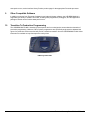
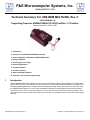
P&E Microcomputer Systems, Inc.
www.pemicro.com
Technical Summary For USB BDM MULTILINK, Rev. C
(PART# USB-ML-12)
Supporting Freescale RS08/HCS08/HC(S)12(X)/ColdFire® V1 Families
Document # PE3374, Version 1.06b
1. Introduction
2. Usage Of The HCS08/HCS12 Multilink Interface
3. Driver Installation On Windows XP/2000/2003/Vista/7
4. Using A USB Hub
5. Connecting To The Target
6. Product Registration
7. Firmware Updates
8. Interface Libraries
9. Other Compatible Software
10. Transition To Production Programming
1
Introduction
P&E’s USB BDM MULTILINK Interface provides access to Background Debug Mode (BDM) on Freescale RS08,
HCS08, HC12, HCS12, and ColdFire® V1 microcontrollers. It is the hardware interface between a USB port on a
Windows 2000/XP/2003/Vista/7 machine and the standard 6-pin “Berg” debug connector on the target. By using
the USB BDM MULTILINK, the user can take advantage of Background Debug Mode to halt normal processor
execution and use a PC to control the processor. The user can then directly control the target’s execution, read/
write registers and memory values, debug code on the processor, and program internal or external FLASH memory
devices.
©2008 P&E Microcomputer Systems, Inc.
ColdFire is a registered trademark of Freescale, Inc.
The pin-out of the connector as specified by Freescale is:
2
Usage Of The USB BDM MULTILINK Interface
The USB BDM MULTILINK can communicate with an RS08, HCS08, HC12, HCS12 or ColdFire V1 processor.
P&E’s software packages will automatically detect the proper communication rate to establish a connection with
the target. For HC12/HCS12 devices, the BDM communication speed may be set (instead of being auto-detected)
by setting the value of the IO_DELAY_CNT variable. The proper IO_DELAY_CNT may be calculated by the
equation:
IO_DELAY_CNT = (120000000 / Fbus) – 1
where Fbus is the bus frequency in hertz.
Note:
RS08 and HCS08 frequencies are always detected automatically.
The Multilink interface will work with targets whose processor power supply is in the range of 1.6V to 5.25V. The
Multilink interface derives its power from the USB port and as such draws less than 1mA from the target.
The USB BDM MULTILINK has a female type B USB connector. Use a Type A to Type B USB extension cable to
connect the interface to the PC.
The USB BDM MULTILINK is a USB device. If a USB Hub is used, it must be a self-powered hub (i.e. with its own
power supply). By default, the USB protocol used is 2.0.
There are two LEDs which protrude through the housing of the USB BDM MULTILINK interface. The Blue LED
indicates that the Multilink interface is powered and running. The Yellow LED indicates that target power has been
detected.
The 6-pin ribbon cable, which allows connection to the target debug connector, is fixed within the Multilink housing.
PIN 1 is denoted by the red stripe running down the ribbon cable.
3
Driver Installation On Windows XP/2000/2003/Vista/7
Before connecting the USB BDM MULTILINK to the PC, the appropriate drivers need to be installed on the PC.
These drivers are automatically installed when installing Freescale’s CodeWarrior or any of P&E’s recent RS08/
HCS08/HC12/HCS12 development packages. If you have installed a recent version of these then the instructions
for manual installation that follow are not necessary. However, Windows 7 users who are installing software
distributed before December 28, 2009 will need to obtain the latest version of the drivers and install them manually.
A copy of the driver installation program may be downloaded from the “Downloads” section of P&E’s “Support
Center” located at http://www.pemicro.com. If you are using third-party software, make sure you have a version
which supports the USB BDM MULTILINK Rev. C interface. Once you have obtained the latest version of the driver
installation program, please use the instructions below to manually install the drivers.
When the cable is plugged in, the operating system should indicate that it has found a driver for the attached “USB
Multilink 2.0”. Follow the instructions in the “Found New Hardware Wizard” dialog for having Windows
automatically install the driver.
If you connected the Multilink interface prior to installing the drivers, Windows will not have been able to find the
appropriate driver and may have disabled the device. If you unplug the device and then plug it in again, Windows
will automatically disable it even if you have installed the drivers. To force Windows to attempt to load the driver
again, perform the following steps while the USB BDM MULTILINK interface is plugged into the computer:
1.
Open the Control Panel: Start Button [ ->Settings ] ->Control Panel. (You will not need to select “Settings” on
Vista and Windows 7).
Technical Summary For USB-ML-12E Rev. C
4
2.
Double Click the “System” Icon. (Windows 7: “System and Security”)
3.
Select the “Hardware” Tab. (Windows 7: “Hardware and Sound”, Windows Vista: skip this step)
4.
Click the “Device Manager” Button. (Windows 7: “Devices and Printers -> Device Manager”)
5.
The “USB-ML-12 Rev. C” device will be shown with an exclamation point next to it. Double-click this device.
6.
Click the “Reinstall Driver…” button and follow the dialog instructions to have Windows automatically install
the driver. (Windows 7: First click the “Driver” tab, then select “Update Driver...”)
7.
If the hardware still has a yellow exclamation mark next to it, right click on it and select uninstall. The USB
Multilink should disappear from the list. Unplug the USB Multilink and then plug it into the PC again. A new
Hardware Found dialog will pop up; follow the dialog instructions and have Windows automatically install the
driver.
Using A USB Hub
The USB BDM MULTILINK is a USB device which is powered from the USB bus. It requires that if a USB hub is
used, it must be a self-powered hub. This means that it has a separate power supply, as opposed to deriving its
power from the PC. It must be able to supply 500mA per port.
5
Connecting To The Target
The following is the proper connection sequence to connect the PC to the target system via the USB BDM
MULTILINK interface:
1. Make sure the target power is OFF and the USB BDM MULTILINK is not connected to either the target or the
PC
2. Connect the Multilink to the target via its ribbon cable. Make sure that the ribbon cable is plugged into the target with the proper orientation. PIN 1 is denoted by the red stripe running down the ribbon cable.
3. Connect the USB Multilink to the PC via a USB cable. The Blue LED on the Multilink should become lit.
4. Turn the target power on. The Yellow LED on the Multilink should become lit.
Before disconnecting the setup, turn the target power off.
6
Product Registration
Please register your USB BDM Multilink at www.pemicro.com/register. This quick registration will ensure that you
receive the latest product information, including software updates, free utilities, and diagnostic tools for use with the
USB BDM Multilink.
7
Firmware Updates
The latest version of the firmware for the Multilink interface is included in P&E software development kits. When the
debugger or programmer is run, if it detects that the Multilink interface firmware is not the latest version it will
automatically update the firmware.
Alternately, the latest version of the firmware may be downloaded from the “Firmware Updates” section of the
“Support Center” located at http://www.pemicro.com.
8
Interface Libraries
P&E produces a set of processor-specific Interface Libraries which allows the user to directly control the USB BDM
MULTILINK from any Windows Development Environment which can interact with a DLL. The interface libraries
come with examples for controlling the Multilink interface from Microsoft Visual C as well as Borland Delphi.
Details of the libraries for the RS08, HCS08, HC(S)12, and ColdFire V1 may be found on our website,
Technical Summary For USB-ML-12E Rev. C
www.pemicro.com, at the Interface Library Routine product page for the appropriate Freescale processor.
9
Other Compatible Software
In addition to support from Freescale Codewarrior and other third party software, the USB BDM Multilink is
supported by a variety of software from P&E, including flash programmers, debuggers, and test application
packages. Details can be found at www.pemicro.com.
10
Transition To Production Programming
The USB BDM MULTILINK is intended for development and is not designed to accomodate the demands of
production programming. However, P&E’s Cyclone programmers are specifically engineered to withstand the
rigors of a production environment and will provide a seamless transition from the USB BDM MULTILINK. More
information is available at: http://www.pemicro.com/cyclone
P&E’s Cyclone PRO
Technical Summary For USB-ML-12E Rev. C