1
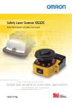
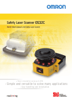
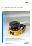
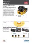
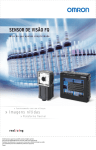
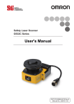
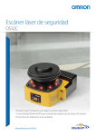
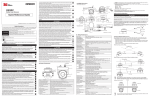
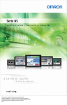
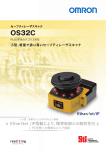
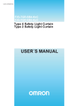
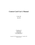
SAFETY LASER SCANNER OS32C
Wo r l d ’s m o s t co m p a c t s a fe ty l a s e r s c a n n e r
»» Power saving up to 50%
» »S i m p l e a n d ve rs a t i l e
» »E a s y h a n d l i n g a n d i n s t a l l a t i o n
Order/version: 2365629/002 (width: 210mm, height: 297mm)
Print type: OS32C Brochure - Central Print, Full color, with extra spotcolor(s)
Produced by Adnovate on 11-jan-2011 at 16:27:41 in Adobe InDesign 5.0.4.682
Low resolution proof not suitable for production purposes
Page: 1
2
Low profile for
easy installation
Omron OS32C Safety Laser Scanner – the World’s
most compact and versatile safety laser scanner
for easy handling and installation with low power
consumption.
The compact body allows installation in small
spaces, e.g. automated guided vehicles and the
detection angle up to 270° provides coverage of two
sides with just one scanner.
Versatile solutions
• For collision avoidance of AGVs (Automated Guided Vehicles)
• For intrusion detection through an entrance
• For presence detection within a machine’s hazardous area
Features
• Easy configuration of complex zones
• Simplified wiring
• Replacable sensor, no reprogramming needed
• Response time can be set from 80 ms to 680 ms
• Cable access options
• Reference Boundary Monitoring function
104.5 mm
142.7 mm
133.0 mm
Order/version: 2365629/002 (width: 210mm, height: 297mm)
Print type: OS32C Brochure - Central Print, Full color, with extra spotcolor(s)
Produced by Adnovate on 11-jan-2011 at 16:27:41 in Adobe InDesign 5.0.4.682
Low resolution proof not suitable for production purposes
Page: 2
3
Detection Angle
270° Max.
104.5 mm
Lowest profile
Compact and versatile safety laser scanner
Safety Zone
3 m Max.
1.3 kg
Lightweight body
Warning Zones 1 & 2
10 m Max.
for easy handling and installation
5W
Low power consumption
reduces battery load on the AGV (3.75 W in standby mode)
Flexible zone configurations
For complex AGV applications, up to 70 combinations – each
with one safety zone and two warning zones – can be set. The
two warning zones can be set to support various purposes
such as warning sound and speed control.
Safety zone
Warning zone 1
Warning zone 2
Order/version: 2365629/002 (width: 210mm, height: 297mm)
Print type: OS32C Brochure - Central Print, Full color, with extra spotcolor(s)
Produced by Adnovate on 11-jan-2011 at 16:27:41 in Adobe InDesign 5.0.4.682
Low resolution proof not suitable for production purposes
Page: 3
4
Versatile scanner solving many applications
Intrusion detection
Reference Boundary Monitoring function supports intrusion
detection without physically blocking the entrance. Supports
various operation patterns by switching zone sets.
Safety zone can be selected
Intrusion detection with vertical installation
Presence detection
Compact body allows for use inside the machine. Detection
angle of 270° provides coverage of two sides with one
scanner.
Guarding inside the machine
Order/version: 2365629/002 (width: 210mm, height: 297mm)
Print type: OS32C Brochure - Central Print, Full color, with extra spotcolor(s)
Produced by Adnovate on 11-jan-2011 at 16:27:41 in Adobe InDesign 5.0.4.682
Low resolution proof not suitable for production purposes
Page: 4
Presence detection of 270°
5
Collision avoidance
Small, light and compact body provides easy installation on an
AGV. Low power consumption (5W) reduces battery load on the
AGV. (3.75 W in standby mode) Up to 70 zone set combinations
support complex AGV tracks.
All-around monitoring
Front/Rear monitoring
Individual sector
indicators*
Ethernet
Stop indicator
Run indicator
Interlock indicator
Warning output
indicator
Status/Diagnostic display
* US patent No.: US 6,753,776 B2
Operating state can be determined
at a glance
Integrated management via Ethernet
Eight sector indicators show the direction of intrusion.
Industry’s first Ethernet-compliant Safety Laser Scanner allows
Front display shows operating state and error codes.
the user to check operating status and analyse the cause of an
emergency stop via LAN even in large-scale applications using
multiple scanners.
Order/version: 2365629/002 (width: 210mm, height: 297mm)
Print type: OS32C Brochure - Central Print, Full color, with extra spotcolor(s)
Produced by Adnovate on 11-jan-2011 at 16:27:41 in Adobe InDesign 5.0.4.682
Low resolution proof not suitable for production purposes
Page: 5
6
New convenient and easy-to-use functions
The OS32C uses time-of-flight (TOF) measurement to
determine distance. The scanner emits a laser pulse, when
the pulse hits an object the signal is reflected to the scanner.
The OS32C then compares the distance/position of the object
against the defined safety zone.
Gap occurs
Safety Output ON
Safety Output OFF
Easy configuration of complex zones
The configuration of the safety zone and warning zones can
be done in real time using a PC. Configurations can also be
created or modified offline.
Reference Boundary Monitoring function
The OS32C constantly monitors reference points and turns
OFF the safety outputs when a shift in its position is detected.
(Per international standard IEC 61496-3, area scanners used
Response time can be set from 80 ms to 680 ms
Response time adjustment can filter out erroneous detections
(machine stoppage) caused by pollutants in the environment.
Order/version: 2365629/002 (width: 210mm, height: 297mm)
Print type: OS32C Brochure - Central Print, Full color, with extra spotcolor(s)
Produced by Adnovate on 11-jan-2011 at 16:27:41 in Adobe InDesign 5.0.4.682
Low resolution proof not suitable for production purposes
Page: 6
in applications where the angle of approach exceeds +/- 30
degrees with respect to the detection plane, must use RBM in
the detection zone.)
7
I/O Block
OS32C-BP
Sensor Block
Replaceable sensor, no reprogramming needed
No reprogramming needed, the configuration is stored in the
I/O block. Replacing a damaged sensor is fast and easy.
OS32C-SP1
Simplified wiring
Cable access options
Omron STI’s innovative I/O method requires fewer inputs
To tailor the OS32C to your installation, two options
when configuring multiple zones. Only 4 inputs are required to
are available for the location of the power and ethernet
select from 6 zone sets. If all 8 inputs are used, up to 70 zone
connections:
sets are available.
• OS32C-BP (Cable access from the back)
• OS32C-SP1 (Cable access from the left side)
These can be selected according to the needs of AGV or
facilities design.
Provides Safety Category 3 safety circuit
without a dedicated controller
Compliant to global safety standards
Order/version: 2365629/002 (width: 210mm, height: 297mm)
Print type: OS32C Brochure - Central Print, Full color, with extra spotcolor(s)
Produced by Adnovate on 11-jan-2011 at 16:27:41 in Adobe InDesign 5.0.4.682
Low resolution proof not suitable for production purposes
Page: 7
OS32C
Safety sensors
OS32C Safety Laser Scanner
• Type 3 Safety Laser Scanner complies with IEC61496-1/-3.
• 70 sets of safety zone and warning zone combinations are available, supporting
complicated changes in working environments.
• A safety radius up to 3 m and warning zone(s) radius up to 10 m can be set.
• 8 Individual Sector Indicators and various LED indications allow the user to
determine scanner status at a glance.
• Reference Boundary Monitoring function prevents unauthorized changes in the
scanner position.
Ordering information
OS32C (Power cable is sold separately.)
Mounting brackets
Description
Remarks
Order code
Type
Remarks
Order code
Back location cable entry
CD-ROM (Configuration software)
OS supported:
Windows 2000,
Windows XP,
Windows Vista
OS32C-BP
Bottom/side mounting bracket
Bottom/side mounting bracket x 1,
unit mounting screws x 4 sets
OS32C-BKT1
Side location cable entry*1
*1
OS32C-SP1
For OS32C-SP1, each connector is located on the left as viewed from the back of the I/O block.
XY axis rotation mounting bracket XY axis rotation mounting bracket x 1, OS32C-BKT2
unit mounting screws x 6 sets,
bracket mounting screws x 1 set
(must be used with OS32C-BKT1)
Note: For a full line-up of accessories and spare parts, please refer to the Z298-E1… datasheet.
Specifications
Sensors
Sensor Type
Type 3 Safety Laser Scanner
Safety Category
Category 3, Performance Level d (ISO13849-1: 2006)
Detection Capability
Non-transparent with a diameter of 70 mm (1.8% reflectivity or greater)
Monitoring Zone
Monitoring Zone Set Count: (Safety Zone + 2 Warning Zones) x 70 sets
Operating Range
Safety zone radius up to 3 m, Warning Zone radius up to 10 m.
Detection Angle
270°
Response Time
Response time from ON to OFF: From 80 ms (2 scans) to 680 ms (up to 17 scans)
Response time from OFF to ON: Response time from ON to OFF + 100 ms to 60 s (Configurable)
Line Voltage
24 VDC +25%/-30% (ripple p-p 2.5 V max.)*1
Power Consumption
Normal operation: 5 W max., 4 W typical (without output load)*2
Standby mode: 3.75 W (without output load)
Safety Output (OSSD)
PNP transistor x 2, load current of 250mA max., residual voltage of 2 V max., load capacity of 2.2 μf max., leak current of 1 mA max. *2,*3,*4
Auxiliary Output (Non-Safety)
NPN/PNP transistor x 1, load current of 100 mA max., residual voltage of 2 V max., leak current of 1 mA max.*3,*4,*5
Warning Output (Non-Safety)
NPN/PNP transistor x 1, load current of 100 mA max., residual voltage of 2 V max., leak current of 1 mA max.*3,*4,*5
Output Operation Mode
Auto Start, Start Interlock, Start/Restart Interlock
Input
External Device Monitoring (EDM) ON: 0 V short (input current of 50 mA), OFF: Open
Start
ON: 0 V short (input current of 20 mA), OFF: Open
Zone Select
ON: 24 V short (input current of 5 mA), OFF: Open
Stand-by
ON: 24 V short (input current of 5 mA), OFF: Open
Connection Type
Power Cable: 18-pin mini-connector (pigtail)
Communication Cable: M12, 4-pin connector
Connection with PC
Communication: Ethernet
Indicators
RUN indicator: Green, STOP indicator: Red, Interlock Indicator: Yellow,Warning Output Indicator: Orange, Status/Diagnostic Display: 2 x 7-segment
LEDs, Intrusion Indicators: Red LED x 8
Enclosure Rating
IP65 (IEC60529)
Dimensions (WxHxD)
133.0 x 104.5 x 142.7 mm (except cable)
Weight (Main Unit only)
1.3 kg
Approvals
EN61496-1 (Type 3 ESPE), EN61496-3 (Type 3 AOPDDR), EN61508 (SIL2), ISO13849-1 (Category 3, Performance Level d), UL508, UL1998,
CAN/CSA-C22.2 No. 14, CAN/CSA-C22.2 No. 0.8
*1
*2
For power source specification, refer to “Safety Precautions” on page 16.
Rated current of OS32C is 1.025 A max. (OS32C 210 mA + OSSD A load + OSSD B load + Auxiliary output load + Warning output load + Functional Inputs). Where functional inputs are:
EDM input ... 50 mA Start input ... 20 mA Standby input ... 5 mA Zone X input ... 5 mA x 8 (eight zone set select inputs)
*3
Output voltage is Input voltage - 2.0 VDC.
*4 Total consumption current of 2 OSSDs, auxiliary output, and warning output must not exceed 700 mA.
*5
Output polarity (NPN/PNP) is configurable via the configuration tool.
8
Order/version: 2365629/002 (width: 210mm, height: 297mm)
Print type: OS32C Brochure - Central Print, Full color, with extra spotcolor(s)
Produced by Adnovate on 11-jan-2011 at 16:27:41 in Adobe InDesign 5.0.4.682
Low resolution proof not suitable for production purposes
Page: 8
OS32C
Safety sensors
Connection
Basic connection with single OS32C unit
Category 3, Performance Level d (ISO13849-1)
E1
PE
0V
Functional Earth (Green)
+24V
24VDC (White)
0VDC (Brown)
S3
Standby input (Violet)
Zone Select 1 (Orange/White)
*4
S2
Zone Select 2 (Orange/Black)
*4
S2
Zone Select 3 (Gray)
*4
S2
Zone Select 4 (Pink)
*4
S2
Zone Select 5 (White/Black)
*4
S2
Zone Select 6 (Tan)
*4
S2
Zone Select 7 (Orange)
*4
S2
Zone Select 8 (Blue/White)
*4
S2
Start (Black)
*3
S1
Auxiliary output (Blue)
*2 ED1
Warning output (Red/Black)
ED2
EDM (Brown/White)
ED1
Safety output B (Yellow)
*1
Safety output A (Red)
*1
OS32C Configuration
- External Device Monitoring Enabled
- Start/Restart Interlock
S1 : Start Input
S2 : Zone Select Switch
S3 : Standby Switch
ED1, ED2: Forced guided relay
M1 : 3-Phase Motor
E1 : 24 VDC Power
ED1
ED2
ED2
M1
*1. External devices (ED1, ED2) are forced guide relays. (G7Z, G7SA, G7S, etc)
*2. If the External Device Monitoring is not used, connect brown/white wires to 0 V, and then turn OFF the
External Device Monitoring with the configuration software.
*3. Use NC-contact for a start input.
*4. For zone select switch setting, refer to OS32C Series User's Manual.
Note: This wiring example is for category 3.
9
Order/version: 2365629/002 (width: 210mm, height: 297mm)
Print type: OS32C Brochure - Central Print, Full color, with extra spotcolor(s)
Produced by Adnovate on 11-jan-2011 at 16:27:41 in Adobe InDesign 5.0.4.682
Low resolution proof not suitable for production purposes
Page: 9
OS32C
Safety sensors
Dimensions
OS32C with Back Location Cable Entry - OS32C-BP
Ethernet cable not shown
Ethernet connector
with M12 cap plug
I/O cable
90.4 [3.56]
Window
158.3 [6.24]
Dust
detection
I/O block
Sensor head
104.3 [4.11]
140.4 [5.53]
Top View
100.0 [3.94]
133.0 [5.24]
M5 x 0.8,
DEPTH 9.0 [0.35]
MAX (x4)
32.8 [1.29]
104.5 [4.12]
67.0 [2.64]
Scan plane
41.4 [1.63]
MTG holes
57.0 [2.25]
27.7 [1.09]
Front View
6.0 [0.24]
50.0 [1.97]
Side View
50.9 [2.01]
121.0 [4.77]
MTG holes
Back View
102.9 [4.05]
142.7 [5.62]
I/O cable assy
88.1 [3.47]
2.0, 3.0, 10.0, 20.0, or 30.0 Meters
30.0 [1.18] dia. OD
71.5 [2.82]
71.3 [2.81]
(min)
Ethernet
cable
I/O cable
270 (10.63)
Bottom View
OS32C with Side Location Cable Entry - OS32C-SP1
I/O block
Ethernet
cable
90.4 [3.56]
Ethernet cable
Window
Dust
detection
I/O cable
Sensor head
104.3 [4.11]
Top View
140.4 [5.53]
133.0 [5.24]
M5 x 0.8,
DEPTH 9.0 [0.35]
MAX (x4)
32.8 [1.29]
104.5 [4.12]
67.0 [2.64]
Scan plane
41.4 [1.63]
MTG holes
121.0 [4.77]
MTG holes
100.0 [3.94]
70.8 [2.79]
Front View
6.0 [0.24]
Back View
57.0 [2.25]
Side View
50.4 [1.99]
18.2 [0.72]
I/O cable
270 [10.63]
102.9 [4.05]
142.7 [5.62]
88.2 [3.47]
71.5 [2.82]
Bottom View
10
Order/version: 2365629/002 (width: 210mm, height: 297mm)
Print type: OS32C Brochure - Central Print, Full color, with extra spotcolor(s)
Produced by Adnovate on 11-jan-2011 at 16:27:41 in Adobe InDesign 5.0.4.682
Low resolution proof not suitable for production purposes
Page: 10
I/O cable assy
25.0 [0.99]
2.0, 3.0, 10.0, 20.0, or 30.0 Meters
30.0 [1.18] dia. OD
39.0 [1.54]
11
Memoseiten_KPP.pdf
11
Order/version: 2365629/002
(width: 210mm, height: 297mm)
Print type: OS32C Brochure - Central Print, Full color, with extra spotcolor(s)
Produced by Adnovate on 11-jan-2011 at 16:27:41 in Adobe InDesign 5.0.4.682
Low resolution proof not suitable for production purposes
Page: 11
23.10.2009 17:25:19
Omron Europe B.V. Wegalaan 67-69, NL-2132 JD, Hoofddorp, The Netherlands. Tel: +31 (0) 23 568 13 00 Fax: +31 (0) 23 568 13 88 www.industrial.omron.eu
Austria
Tel: +43 (0) 2236 377 800
www.industrial.omron.at
Germany
Tel: +49 (0) 2173 680 00
www.industrial.omron.de
Portugal
Tel: +351 21 942 94 00
www.industrial.omron.pt
Turkey
Tel: +90 212 467 30 00
www.industrial.omron.com.tr
Belgium
Tel: +32 (0) 2 466 24 80
www.industrial.omron.be
Hungary
Tel: +36 1 399 30 50
www.industrial.omron.hu
Russia
Tel: +7 495 648 94 50
www.industrial.omron.ru
United Kingdom
Tel: +44 (0) 870 752 08 61
www.industrial.omron.co.uk
Czech Republic
Tel: +420 234 602 602
www.industrial.omron.cz
Italy
Tel: +39 02 326 81
www.industrial.omron.it
South Africa
Tel: +27 (0)11 608 3041
www.industrial.omron.co.za
Denmark
Tel: +45 43 44 00 11
www.industrial.omron.dk
Netherlands
Tel: +31 (0) 23 568 11 00
www.industrial.omron.nl
Spain
Tel: +34 913 777 900
www.industrial.omron.es
Finland
Tel: +358 (0) 207 464 200
www.industrial.omron.fi
Norway
Tel: +47 (0) 22 65 75 00
www.industrial.omron.no
Sweden
Tel: +46 (0) 8 632 35 00
www.industrial.omron.se
France
Tel: +33 (0) 1 56 63 70 00
www.industrial.omron.fr
Poland
Tel: +48 (0) 22 645 78 60
www.industrial.omron.pl
Switzerland
Tel: +41 (0) 41 748 13 13
www.industrial.omron.ch
More Omron representatives
www.industrial.omron.eu
Automation Systems
• Programmable logic controllers (PLC) • Human machine interfaces (HMI) • Remote I/O • Industrial PC’s • Software
Motion & Drives
• Motion controllers • Servo systems • Inverters
Control Components
• Temperature controllers • Power supplies • Timers • Counters • Programmable relays • Digital panel indicators • Electromechanical relays • Monitoring products • Solid-state relays • Limit switches • Pushbutton switches • Low voltage switch gear
Sensing & Safety
• Photoelectric sensors • Inductive sensors • Capacitive & pressure sensors • Cable connectors • Displacement & width-measuring sensors • Vision systems • Safety networks • Safety sensors • Safety units/relay units • Safety door/guard lock switches CD_En-01+OS32C+Brochure
Although we strive for perfection, Omron Europe BV and/or its subsidiary and affiliated companies do not warrant
or make any representations regarding the correctness or completeness of the information described in this document.
We reserve the right to make any changes at any time without prior notice.
Order/version: 2365629/002 (width: 210mm, height: 297mm)
Print type: OS32C Brochure - Central Print, Full color, with extra spotcolor(s)
Produced by Adnovate on 11-jan-2011 at 16:27:41 in Adobe InDesign 5.0.4.682
Low resolution proof not suitable for production purposes
Page: 12