1
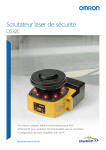
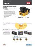
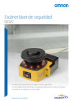
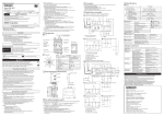
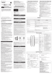
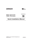
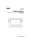
Safety Laser Scanner OS32C World's Most Compact Level Safety Laser Scanner Power consumption saving up to 50% » Simple and versatile to solve many applications » Easy handling and installation Low profile allows installation in small spaces For collision avoidance of AGVs (Automated Guided Vehicles) For intrusion detection through an entrance ach For presence detection within a machine's hazardous area 104.5mm 142.7mm 133.0mm Flexible zone configurations For complex AGV applications, up to 70 combinations - each with one safety zone and two warning zones can be set. The two warning zones can be set to Safety Zone support various purposes such as Warning Zone 1 warning sound Warning Zone 2 and speed control. 2 Industry Best Simplified Wiring OMRON STI's innovative I/O method requires fewer inputs when configuring multiple zones. Only 4 inputs are required to select from 6 zone sets. If all 8 inputs are used, up to 70 zone sets are available. * U.S. patent pending. Features Safety Zone 3 m Max. Detection Angle 270¡ Max. 270°detection angle Warning Zones 1&2 10 m Max. World’s Most Compact Level Small Size 104.5 mm Compact and versatile safety laser scanner 1.3 kg Lightweight Lightweight body for easy handling and installation Low Power Consumption 5w Low power consumption reduces battery load on the AGV (3.75 W in standby mode) Industry First Operating state can be determined at a glance Integrated management via Ethernet Eight sector indicators show the direction of intrusion. Front display shows operating state and error codes. Industry's first Ethernet-compliant Safety Laser Scanner allows the user to check operating state and analyze the cause of an emergency stop via LAN even in large-scale applications using multiple scanners. Individual sector indicators* Run indicator Interlock indicator Stop indicator Warning output indicator Ethernet Status/Diagnostic display * US patent No.: US 6,753,776 B2 3 Applications Collision Avoidance Small, light and compact body provides for easy installation on an AGV. Low power consumption (5W) reduces battery load on the AGV. (3.75 W in standby mode) Up to 70 zone set combinations support complex AGV V tracks. Front/Rear monitoring All-around Monitoring Intrusion Detection Reference Boundary Monitoring function supports intrusion detection without physically blocking the entrance. Supports various operation patterns by switching zone sets. Intrusion detection with vertical installation Safety zone can be selected Presence Detection Compact body allows for use inside the machine. Detection angle of 270° provides coverage of two sides with one scanner. Guarding inside the machine 4 Presence detection of 270° New convenient and easy-to-use functions NEW NEW Replacable sensor, no reprogramming needed Reference Boundary Monitoring function No reprogramming needed, the configuration is stored in the I/O block. Replacing a damaged sensor is fast and easy. The OS32C constantly monitors reference points and turns OFF the safety outputs when a shift in its position is detected. I/O Block (Per international standard IEC 61496-3, area scanners used in applications where the angle of approach exceeds +/- 30 degrees with respect to the detection plane, must use RBM in the detection zone.) Gap occurs Detachable Sensor Block Safety Output ON Safety Output OFF Cable Access Options Easy configuration of complex zones To tailor the OS32C to your installation, two options are available for the location of the power and ethernet connections: OS32C-BP (Cable access from the back) OS32C-SP1 (Cable access from the left side) These can be selected according to the needs of AGV or facilities design. The configuration of the safety zone and warning zones can be done in real time using a PC. Configurations can also be created or modified offline. OS32C with cable access from the back (OS32C-BP) OS32C with cable access from the left side (OS32C-SP1) Provides Safety Category 3 safety circuit without a dedicated controller Compliant to global safety standards Response time can be set from 80 ms to 680 ms Response time adjustment can filter out erroneous detections (machine stoppage) caused by pollutants in the environment. ISO13849-1 PLd SIL2 Operating Theory of OS32C The OS32C uses time-of-flight (TOF) measurement to determine distance. The scanner emits a laser pulse, when the pulse hits an object the signal is reflected to the scanner. The OS32C then compares the distance/position of the object against the defined safety zone. 5 Safety Laser Scanner OS32C OS32C Safety Laser Scanner Featuring the World’s Most Compact Level Size (104.5 mm), Low Power Consumption (5 W) and Lightweight (1.3 kg). • Type 3 Safety Laser Scanner complies with IEC61496-1/-3. • 70 sets of safety zone and warning zone combinations are available, supporting complicated changes in working environments. • A safety radius up to 3 m and warning zone(s) radius up to 10 m can be set. • 8 Individual Sector Indicators and various LED indications allow the user to determine scanner status at a glance. • The Configuration Tool makes complex zone combinations easy. • Provides a safety circuit of Performance Level d and safety category 3 (ISO13849-1) without a dedicated controller. • The response time is configurable from 80 ms to a maximum of 680 ms. • Provides integrated management via Ethernet. • Reference Boundary Monitoring function prevents unauthorized changes in the scanner position. • Minimal down time, sensor block can be replaced without the need to reprogram. Refer to “Safety Precautions” on page 16. Ordering Information OS32C (Power cable is sold separately.) Appearance Description OS32C with back location cable entry Model Remarks OS32C-BP CD-ROM (Configuration software) OS supported: Windows 2000, Windows XP, Windows Vista OS32C with side location cable entry * OS32C-SP1 * For OS32C-SP1, each connector is located on the left as viewed from the back of the I/O block. Power Cable Appearance Description Model Cable length: 3 m OS32C-CBL-03M Cable length: 10 m OS32C-CBL-10M Cable length: 20 m OS32C-CBL-20M Cable length: 30 m OS32C-CBL-30M Description Model Cable length: 2 m OS32C-ECBL-02M Cable length: 5 m OS32C-ECBL-05M Cable length: 15 m OS32C-ECBL-15M Remarks One cable is required per sensor. Ethernet Cable Appearance Note: An ethernet cable with an M12, 4-pin connector is required. 6 Remarks Required for configuration and monitoring. OS32C Mounting Brackets Appearance Description Bottom/side mounting bracket XY axis rotation mounting bracket Model OS32C-BKT1 OS32C-BKT2 Remarks Bottom/side mounting bracket x 1, unit mounting screws x 4 sets XY axis rotation mounting bracket x 1, unit mounting screws x 6 sets, bracket mounting screws x 1 set (must be used with OS32C-BKT1) Simple mounting bracket OS32C-BKT3 Protective cover for window OS32C-BKT4 Mounting stand OS32C-MT Hardware kit for mounting stand OS32C-HDT Simple mounting brackets x 2, unit mounting screws x 4 sets * When using a mounting stand, use an OS32C with side location cable entry (OS32C-SP1). The OS32C with back location cable entry (OS32C-BP) cannot be mounted. Use with mounting brackets (OS32C-BKT1 and OS32C-BKT2). Mounting screws x 3 sets Use this when mounting a bracket to the mounting stand. * There are eight OS32C mounting screws: four screws for singular use, and four screws for protective cover for window. Accessories Appearance Description Model Remarks Scan window OS32C-WIN-KT Spare for replacement Sensor block without I/O block OS32C-SN Spare for replacement With cable access from the back OS32C-CBBP Spare for replacement With cable access from the left side OS32C-CBSP1 Spare for replacement I/O block 7 OS32C Rating/Performance Sensor Type Type 3 Safety Laser Scanner Safety Category Category 3, Performance Level d (ISO13849-1: 2006) Detection Capability Non-transparent with a diameter of 70 mm (1.8% reflectivity or greater) Monitoring Zone Monitoring Zone Set Count: (Safety Zone + 2 Warning Zones) x 70 sets Operating Range Safety zone radius up to 3 m, Warning Zone radius up to 10 m. Maximum Measurement Error 100 mm *1 Detection Angle 270° Angular Resolution 0.4° Laser Beam Diameter 6 mm at optics cover, 14 mm at 3 m. Response Time Response time from ON to OFF: From 80 ms (2 scans) to 680 ms (up to 17 scans) Response time from OFF to ON: Response time from ON to OFF + 100 ms to 60 s (Configurable) Zone Switching Time 20 to 320 ms Line Voltage 24 VDC +25%/-30% (ripple p-p 2.5 V max.) *2 Power Consumption Normal operation: 5 W max., 4 W typical (without output load) *3 Standby mode: 3.75 W (without output load) Emission Source (Wavelength) Infrared Laser Diode (905 nm) Laser Protection Class Class 1: IEC/EN60825-1 (2007) Class 1: JIS6802 (2005) Class I: CFR21 1040.10, 1040.11 Safety Output (OSSD) PNP transistor x 2, load current of 250mA max., residual voltage of 2 V max., load capacity of 2.2 µf max., leak current of 1 mA max. *3, *4, *5 Auxiliary Output (Non-Safety) NPN/PNP transistor x 1, load current of 100 mA max., residual voltage of 2 V max., leak current of 1 mA max. *4, *5, *7 Warning Output (Non-Safety) NPN/PNP transistor x 1, load current of 100 mA max., residual voltage of 2 V max., leak current of 1 mA max. *4, *5, *7 Output Operation Mode Auto Start, Start Interlock, Start/Restart Interlock Input External Device Monitoring (EDM) ON: 0 V short (input current of 50 mA), OFF: Open Start ON: 0 V short (input current of 20 mA), OFF: Open Zone Select ON: 24 V short (input current of 5 mA), OFF: Open Stand-by ON: 24 V short (input current of 5 mA), OFF: Open Connection Type Power Cable: 18-pin mini-connector (pigtail) Communication Cable: M12, 4-pin connector Connection with PC *6 Communication: Ethernet OS Supported: Windows 2000, Windows XP, Windows Vista Indicators RUN indicator: Green, STOP indicator: Red, Interlock Indicator: Yellow,Warning Output Indicator: Orange, Status/Diagnostic Display: 2 x 7-segment LEDs, Intrusion Indicators: Red LED x 8 Protective Circuit Protection against output load short and reverse power connection Ambient Temperature Operation: -10 to 50 deg. C, Storage: -25 to 70 deg. C Ambient Humidity Operation & Storage: 95% RH max., non-condensing Ambient Operation Illumination Incandescent lamp: Illumination on receiving surface 1500 lx max. (an angle of laser scanning plane and disturbance light must be +/-5 degrees or more) Enclosure Rating IP65 (IEC60529) Enclosure Sensor head: Die-cast aluminum, optical cover: Polycarbonate, I/O block: Die-cast aluminum Dimensions (WxHxD) 133.0 x 104.5 x 142.7 mm (except cable) Dielectric Withstand Voltage 350 VAC, 50/60 Hz, 1 minute Insulation Resistance 20 mega-ohm or higher (500 VDC) Impact Resistance 98 m/s2 1,000 times for each of X, Y, and Z directions (IEC 60068-2-29) Vibration 10 to 55 Hz double-amplitude of 0.7 mm, 20 sweepings for X, Y, and Z directions (IEC60068-2-6) Weight (Main Unit only) 1.3 kg Power Cable Up to 30 m Communication Cable Up to 100 m for 100 BASE-T Cat 5 cable Accessories CD-ROM (User’s Manual and Configuration Tool) EN61496-1 (Type 3 ESPE), EN61496-3 (Type 3 AOPDDR), EN61508 (SIL2), IEC61496-1 (Type 3 ESPE), IEC61496-3 (Type 3 AOPDDR), IEC61508 (SIL2), ISO13849-1 (Category 3, Performance Level d), UL508, UL1998, CAN/CSA-C22.2 No. 14, CAN/CSA-C22.2 No. 0.8 *1. An additional measurement error may need to be added due to reflective backgrounds. *2. For power source specification, refer to “Safety Precautions” on page 16. *3. Rated current of OS32C is 1.025 A max. (OS32C 210 mA + OSSD A load + OSSD B load + Auxiliary output load + Warning output load + Functional Inputs). Where functional inputs are: EDM input ... 50 mA Start input ... 20 mA Standby input ... 5 mA Zone X input ... 5 mA x 8 (eight zone set select inputs) *4. Output voltage is Input voltage - 2.0 VDC. *5. Total consumption current of 2 OSSDs, auxiliary output, and warning output must not exceed 700 mA. *6. An ethernet cable with an M12, 4-pin connector is required. *7. Output polarity (NPN/PNP) is configurable via the configuration tool. Approvals 8 OS32C Connection Basic connection with single OS32C unit Category 3, Performance Level d (ISO13849-1) E1 PE 0V Functional Earth (Green) +24V 24VDC (White) 0VDC (Brown) S3 Standby input (Violet) Zone Select 1 (Orange/White) *4 S2 Zone Select 2 (Orange/Black) *4 S2 Zone Select 3 (Gray) *4 S2 Zone Select 4 (Pink) *4 S2 Zone Select 5 (White/Black) *4 S2 Zone Select 6 (Tan) *4 S2 Zone Select 7 (Orange) *4 S2 Zone Select 8 (Blue/White) *4 S2 Start (Black) *3 S1 Auxiliary output (Blue) Warning output (Red/Black) S1 : Start Input S2 : Zone Select Switch S3 : Standby Switch ED1, ED2: Forced guided relay M1 : 3-Phase Motor E1 : 24 VDC Power *2 ED1 ED2 EDM (Brown/White) ED1 Safety output B (Yellow) *1 Safety output A (Red) *1 ED1 ED2 ED2 M1 *1.External devices (ED1, ED2) are forced guide relays. (G7Z, G7SA, G7S, etc) *2.If the External Device Monitoring is not used, connect brown/white wires to 0 V, and then turn OFF the External Device Monitoring with the configuration software. *3.Use NC-contact for a start input. *4.For zone select switch setting, refer to OS32C Series User's Manual. Note: This wiring example is for category 3. OS32C Configuration - External Device Monitoring Enabled - Start/Restart Interlock Connecting to AGV Controls Category 3, Performance Level d (ISO13849-1) AGV Controls Functional Earth (Green) Power (24VDC) 24VDC (White) 0VDC (Brown) Zone Control Standby input (Violet) Zone Select 1 (Orange/White) Zone Select 2 (Orange/Black) +24VDC Zone Select 3 (Gray) Zone Select 4 (Pink) Zone Select 5 (White/Black) Zone Select 6 (Tan) Zone Select 7 (Orange) Zone Select 8 (Blue/White) Auxiliary Control Start (Black) +24VDC Auxiliary output (Blue) Warning output (Red/Black) EDM (Brown/White) Stop/Brake Control Safety output B (Yellow) Safety output A (Red) OS32C Configuration - External Device Monitoring Disabled - Automatic Start Note: This wiring example is for category 3. In addition, the circuit configuration of the stop/deceleration control must meet the requirements of category 3. 9 OS32C Connecting to the Controller G9SA-301 Category 3, Performance Level d (ISO13849-1) E1 PE 0V +24V Functional Earth (Green) 24VDC (White) 0VDC (Brown) S4 Standby input (Violet) Zone Select 1 (Orange/White) *4 S2 Zone Select 2 (Orange/Balck) *4 S2 Zone Select 3 (Gray) *4 S2 Zone Select 4 (Pink) *4 S2 Zone Select 5 (White/Black) *4 S2 Zone Select 6 (Tan) *4 S2 Zone Select 7 (Orange) *4 S2 Zone Select 8 (Blue/White) *4 S2 PLC IN1 IN2 OUT *2 Start (Black) S1 Auxiliary output (Blue) Warning output (Red/Black) EDM (Brown/White) *3 Safety output B (Yellow) Safety output A (Red) ED3 *1 ED1 ED1 *1 ED2 S3 ED2 A1 A2 T11 T12 T31 T32 13 23 33 41 3 4 a K2 K1 K1 b K2 M K1 1 K2 a b Control Circuit 2 5 JP 1 2 3 4 5 6 6 PE T21 T23 T22 A 14 B *1 ED1, ED2: Forced guided relay ED3 : Solid state contactor (G3J) M : 3-Phase Motor S1 : Start Input (use for releasing lockout) S2 : Zone Select Switch S3 : Reset Switch S4 : Standby Switch E1 : 24 VDC Power PLC : Programmable Controller (This is for monitoring only and unrelated to a safety system) ED1 24 34 ED2 42 *1 *1. External devices (ED1, ED2) are forced guide relays. (G7Z, G7SA, G7S, etc) *2. Use NC-contact for a start input. *3. If the External Device Monitoring is not used, connect brown/white wires to 0V, and then turn OFF the External Device Monitoring with the configuration software. *4. For zone select switch setting, refer to OS32C Series User’s Manual. Note: This wiring example is for category 3. 10 OS32C System Components and Functions (10) (9) (11) (8) (7) (6) (12) (13) (5) (1) (2) Number (3) (4) Component Function (1) RUN indicator (green) Will turn ON when safety zone is clear and OSSDs are ON. (2) Interlock Indicator (yellow) Will turn ON when in interlock state, blink under lockout, and blink in case of a failure. (3) Status/Diagnostic Display The scanner status, configuration/operation, or failure is displayed. (4) Warning Output Indicator (orange) Will turn ON when the warning output is ON. (5) STOP indicator (red) Will turn ON when safety zone is blocked, OSSD are OFF or under interlock state. (6) Dust Ring Dust detection cover with reflective surface, for dust accumulation detection (7) Individual Sector Indicators Will turn ON when an intrusion is detected in the safety zone, 8 sectors total. Each sector = 33.75°. (8) Scan window The window where the laser light is emitted and received. (9) Ethernet Connector Used for Ethernet cable connection. * (10) Power Connector 18-pin connector (pigtail). * (11) I/O Block Connector module (12) Center of rotation Indicates the location of the axis around which the laser emits. (13) Sensor block Sensor head; field replaceable. * For OS32C-SP1, each connector is located on the left as viewed from the back of the I/O block. 11 OS32C External Dimensional Drawings (Unit: mm [inch]) OS32C with Back Location Cable Entry OS32C-BP Ethernet cable not shown Ethernet connector with M12 cap plug I/O cable 90.4 [3.56] Window 158.3 [6.24] Dust detection I/O block Sensor head 104.3 [4.11] 140.4 [5.53] Top View 100.0 [3.94] 133.0 [5.24] M5 x 0.8, DEPTH 9.0 [0.35] MAX (x4) 32.8 [1.29] 104.5 [4.12] 67.0 [2.64] Scan plane 41.4 [1.63] MTG holes 57.0 [2.25] 27.7 [1.09] Front View 6.0 [0.24] 50.0 [1.97] Side View 50.9 [2.01] 121.0 [4.77] MTG holes Back View 102.9 [4.05] 142.7 [5.62] I/O cable assy 2.0, 3.0, 10.0, 20.0, or 30.0 Meters 30.0 [1.18] dia. OD 88.1 [3.47] 71.5 [2.82] 71.3 [2.81] (min) Ethernet cable I/O cable 270 (10.63) Bottom View OS32C with Side Location Cable Entry OS32C-SP1 I/O block Ethernet cable 90.4 [3.56] Ethernet cable Window Dust detection I/O cable Sensor head 104.3 [4.11] Top View 140.4 [5.53] 133.0 [5.24] M5 x 0.8, DEPTH 9.0 [0.35] MAX (x4) 67.0 [2.64] Scan plane Front View 6.0 [0.24] 18.2 [0.72] I/O cable 270 [10.63] 102.9 [4.05] 142.7 [5.62] 88.2 [3.47] 71.5 [2.82] Bottom View I/O cable assy 25.0 [0.99] 57.0 [2.25] Side View 50.4 [1.99] Back View 12 32.8 [1.29] 104.5 [4.12] 41.4 [1.63] MTG holes 121.0 [4.77] MTG holes 100.0 [3.94] 70.8 [2.79] 2.0, 3.0, 10.0, 20.0, or 30.0 Meters 30.0 [1.18] dia. OD 39.0 [1.54] OS32C OS32C with Top Guard Kit OS32C-BP + OS32C-BKT4 150.4 [5.93] 107.5 [4.24] 93.4 [3.68] 3.0 [0.12] 4-5.6 [0.22] dia. 112.4 [4.43] 63.0 [2.48] 41.4 [1.63] 67.0 [2.64] Scan Plane 27.7 [1.09] 6.0 [0.24] 50.0 [1.97] 145.7 [5.74] 121.0 [4.77] Side View Back View OS32C with Bottom/Side Mounting Brackets OS32C-BP + OS32C-BKT1 103.7 [4.08] 97.7 [3.85] 3-6.4 [0.25] dia. 116.7 [4.60] 39.9 [1.57] 4.9 [0.19] 79.2 [3.12] Scan plane 69.2 [2.73] 12.2 [0.48] 50.0 [1.97] 24.5 [0.97] 37. 9 [1.49] 23.3 [0.92] 41.0 [1.62] 4.2 [0.17] 93.7 [3.69] Back View Side View 155.9 [6.14] 106.0 [4.17] 4-5.3 [0.21] dia. 102.4 [4.03] 66.4 [2.62] 144.4 [5.69] 54.5 [2.15] 23.3 [0.92] Bottom View OS32C with Simple Mounting Bracket OS32C-BP + OS32C-BKT3 103.4 [4.08] 27.7 [1.09] 104.5 [4.12] 67.0 [2.64] 26.8 [1.05] Scan plane 52.8 [2.08] 13.3 [0.52] (×4) 12.0 [0.47] (x4) Slots M5 screws, split and flat washers hardware user supplied 50.0 [1.97] 169.0 [6.66] 155.7 [6.13] Back View Side View 185.0 [7.29] In order to comply with Section 4.2.16 of IEC 61496-3, when the OS32C is mounted where the scanner position could change (e.g. as the result of an impact), additional mechanical means, such as serrated or toothed lock washers, must be employed in the mounting hardware. Bottom View 13 OS32C OS32C with Bottom/Side Mounting Brackets and Top Guard Kit OS32C-BP + OS32C-BKT1 + OS32C-BKT4 154.7 [6.09] 107.5 [4.24] 103.7 [4.08] 97.7 [3.85] 3-6.4 [0.25] dia. 124.9 [4.92] 4.9 [0.19] 79.2 [3.12] Scan Plane 75.2 [2.96] 24.5 [0.97] 39.9 [1.57] 12.2 [0.48] 50.0 [1.97] 23.3 [0.92] 41.0 [1.62] 4.8 [0.19] Back View 37.9 [1.49] 93.7 [3.69] Side View 155.9 [6.14] 106.0 [4.17] 4-5.3 [0.21] dia. 102.4 [4.03] 144.4 [5.69] 66.4 [2.62] 54.5 [2.15] 23.3 [0.92] Bottom View OS32C with Bottom/Side Mounting Brackets and XY Axis Rotation Mounting Kit OS32C-BP + OS32C-BKT1 + OS32C-BKT2 111. 4 [4.39] 4-5.3 [0.21] dia. 132.7 [5.23] 95.2 [3.75] Scan plane 48.0 [1.89] 99.2 [3.91] 55.9 [2.20] 43.0 15.0° [1.69] 7.5° 28.2 [1.11] 50.0 [1.97] 17.0 [0.67] 93.5 [3.68] 150.5 [5.93] For Y-angular adjustment (x3) slots Use M6 hex head screws, split and flat washers hardware user supplied 46.0 [1.81] Side View Back View (For back mounting) 163.7 [6.45] 119.7 [4.72] R47.5 [1.87] 15.0° 7.5° Hardware for Y-adjustment 166.3 [6.55] 151.1 [5.95] 4-5.3 [0.21] dia. 102.4 [4.03] 163.0 [6.42] 42.2 [1.66] 17.4 [0.69] 2-R72 [2.83] 6.4 [0.25] Back View (For Y-anglular adjustment) 54.5 [2.15] 37.0 [1.46] Bottom View In order to comply with Section 4.2.16 of IEC 61496-3, when the OS32C is mounted where the scanner position could change (e.g. as the result of an impact), additional mechanical means, such as serrated or toothed lock washers, must be employed in the mounting hardware. 14 OS32C OS32C with Bottom/Side Mounting Brackets, XY Axis Rotation Mounting Kit and Top Guard Kit OS32C-BP + OS32C-BKT1 + OC32C-BKT2 + OS32C-BKT4 168.4 [6.63] 111.4 [4.39] 107.5 [4.24] 4-5.3 [0.21] dia. 141.0 [5.55] 99.2 [3.91] 95.2 [3.75] 48.0 [1.89] SCAN PLANE 55.9 [2.20] 7.5° 50.0 [1.97] 17.0 [0.67] 93.5 [3.68] 150.5 [5.93] 28.2 [1.11] 4.8 [0.19] 46.0 [1.81] Side View Back View (For back mounting) For Y-angular adjustment (x3) slots Use M6 hex head screws, split and flat washers hardware user supplied 15.0° 43.0 [1.69] 163.7 [6.45] 119.7 [4.72] R47.5 [1.87] 15.0° 7.5° Hardware for Y-adjustment 166.3 151.1 [6.55] [5.95] 4-5.3 [0.21] dia. 102.4 [4.03] 163.0 [6.42] 42.2 [1.66] 17.4 [0.69] 2-R72 [2.83] 37.0 [1.46] 54.5 [2.15] 6.4 [0.25] Back View (For Y-angular adjustment) Bottom View In order to comply with Section 4.2.16 of IEC 61496-3, when the OS32C is mounted where the scanner position could change (e.g. as the result of an impact), additional mechanical means, such as serrated or toothed lock washers, must be employed in the mounting hardware. OS32C with Bottom/Side Mounting Brackets, XY Axis Rotation Mounting Kit, Mounting Stand and Mounting Stand Hardware Kit OS32C-SP1 + OS32C-BKT1 + OS32C-BKT2 + OS32C-MT + OS32C-HDT 203.2 [8.00] 609.6 [24.00] 637.2 [25.09] 137.2 [5.40] 424.0 [16.69] 355.1 [13.98] 286. 2 [11.27] 209.6 [8.25] 217.3 [8.56] 111.7 [4.40] 165.1 [6.50] 190.5 [7.50] View A A 235.0 [9.25] 250.8 [9.87] 15 OS32C Power Cable OS32C-CBL-@@M L (56) (90) (30) Sizes are as below Name plate Vinyl insulated round cable (diameter max. 10 mm) Black 15-core (conductor section area 0.3 mm2, insulator diameter max. 1.5 mm) Standard length L (See ) Model Number OS32C-CBL-03M L 3m OS32C-CBL-10M OS32C-CBL-20M 10 m 20 m OS32C-CBL-30M 30 m Ethernet Cable OS32C-ECBL-@@M D-coding 3 4 L 44.7 54.7 1 2 Sizes are as below M12 RJ45 Twist tie Vinyl insulated round cable (diameter max 6.5mm) Light Blue 4-core (conductor section area 0.34mm2, insulator diameter max 1.57mm) Standard length L (See ) Model Number OS32C-ECBL-02M L 2m OS32C-ECBL-05M OS32C-ECBL-15M 5m 15 m Safety Precautions Description shown below is only a guideline to choose a safety laser scanner. To use the product properly, you must read the instruction manual that comes with the product. Legislation and Standards 1. Application of an OS32C sensor by itself cannot receive the type 5) JIS standards JIS B 9704-1: 2006, JIS B 9704-3: 2004 (Type3 ESPE) (3) This product received the following approvals from TÜV approval provided by Article 44-2 of the Labor Safety and Health Law Rheinland of the EU. of Japan. It is necessary to apply it as a system. Therefore, when • EC Type-Examination in accordance with the EU Machinery using this product in Japan as a "safety system for presses and Directive, shearing machines" as prescribed in Article 42 of the Labor Safety Type 3 ESPE (IEC61496-1), and Health Law, the complete system must receive the type approval. 2. (1) This product is electro-sensitive protective equipment (ESPE) Type 3 AOPDDR (IEC61496-3) • TÜV Rheinland type approval, in accordance with European Union (EU) Machinery Directive Type 3 ESPE (IEC61496-1), Index Annex IV, B, Safety Components, Item 1. Type 3 AOPDDR (IEC61496-3) (2) This product complies with the following legislation and Safety Precautions standards: 1) EU legislation • Machinery Directive 98/37/EC, 2006/42/EC • EMC Directive 2004/108/EC 2) European standards EN61496-1: 2004 (Type3 ESPE), EN61496-3: 2001 (Type3 AOPDDR), EN61508 (SIL-2), EN954-1 The Alert symbols and their meanings ensure safe use of the products In order to use the OS32C safely, the precautions listed in this manual are indicated by alert symbols. The descriptions must be followed, failure to follow all precautions and alerts may result in an unsafe installation or operation. The following indictions and symbols are used. 3) International standards IEC61496-1: 2004 (Type3 ESPE), WARNING Indicates a potentially hazardous situation which, if not avoided, will result in minor or moderate injury, or may result in serious injury or death. Additionally there may be significant property damage. CAUTION Indicates a potentially hazardous situation which, if not avoided, will result in minor or moderate injury, or there may be property damage. IEC61496-3: 2008 (Type 3 AOPDDR), IEC61508 (SIL-2), ISO13849-1 4) North American Standards: per UL File E241445, US and C-UL approvals (CNN: NIPM/NIPM7). • ANSI/UL 508 (Industrial Control Equipment) • IEC 61496-1 (Type 3 ESPE) • IEC 61496-3 (Type 3 AOPDDR) • UL 1998 (Software in Programmable Components) • IEC 61508 (Functional Safety of Electrical/Electronic/ Programmable Electronic Safety-Related Systems) Meanings of Alert Symbols • IEC 61508-3 (Functional Safety of Electrical/Electronic/ Programmable Electronic Safety-Related Systems - Part 3: Software Requirements) • CAN/CSA-C22.2 No. 14 (Industrial Control Equipment) • CAN/CSA-C22.2 No. 0.8 (Safety Functions Incorporating Electronic Technology) 16 Indicates prohibited actions. OS32C WARNING An OS32C is an electro-sensitive protective equipment designed to guard personnel working around hazardous machinery. Whether a specific machine application and the OS32C system installation complies with safety regulations depends on the proper application, installation, maintenance and operation of the OS32C system. These items are the responsibility of the purchaser, installer and user. Additional guarding may be required to prohibit access to dangerous areas not covered by the OS32C system. Perform the test procedure in this document at installation, after maintenance, adjustment, repair or modification to the machine controls, tooling or the OS32C system. Perform only the test and repair procedures outlined in the OS32C user's manual. Additional measurement error resulting from reflective backgrounds may need to be added to the measurement error of the OS32C. User WARNING The administrator is responsible for the selection and training of personnel to properly install, operate, and maintain the machine and its safeguarding systems. An OS32C system should only be installed, verified and maintained by a qualified person. A qualifed person is defined as "an individual who understands, is trained on, and demonstrates competence with the construction, operation or maintenance of the machinery and the hazards involved." (ANSI/PMMI B155.12006) The machine requirements WARNING The guarded machine must be able to stop anywhere in its cycle. Do not use an OS32C on a press with a full revolution clutch. The guarded machine must have a consistent stopping time and adequate control mechanisms. All safety-related machine control elements must be designed so that an alarm in the control logic or failure of the control circuit does not lead to a failure to danger. Do not use the auxiliary output or warning output for safety applications. A human body may not be detected even if a failure of OS32C occurrs, resulting in serious injuries. Installation WARNING The main unit must be securely mounted and its cable connectors must be tightly attached. A start switch to release interlock must be installed where an operator can observe the monitored/guarded zone as a whole and cannot operate the switch within the hazardous zone. A protective mechanism must be installed to prevent a hazardous condition in the event of a subsequent machine component failure. The OS32C does not protect against ejected flying material. Severe smoke and particulate matter may degrade the efficiency of an OS32C, causing it to unexpectedly enter a Machine Stop state. To use the protective function of the OS32C, a safety zone must be properly defined and configured. If the response time is changed, re-calculation of the safety distance is required. This may require reconfiguration of the safety zones or re-installation of the OS32C. If the safety distance is not appropriate for the application, the machine may not stop before contact with the hazardous part, resulting in serious injuries or death. When using more than one OS32C, mutual interference should be prevented. This may require different scanner positions or physical shields to be installed. To ensure a protection degree of IP65, DO NOT use this product without proper sealing of the cable connector, I/O block, and scan window. If the external zone switching device momentarily exceeds the configured number of active zone inputs during the zone switch, an additional Zone Delay may be incurred in the event that wiring of a zone set select input fails.The external zone switching device must properly sequence so the configured number of active inputs is not exceeded in order to guarantee that failed zone set select input wiring will be detected within the normal Zone Switching Time described below. If an insufficient Zone Delay is used for the actual worst case switching time of the installation, the OS32C might start monitoring the wrong zone during the switching period !Also, if an insufficient Zone Delay is used for the actual worst case switching time of the installation, there might be a fault condition during the zone switching period! If Tstart is configured without consideration of TmaxReaction, object detection within the new safety zone after switching and turning OFF of the safety outputs may be delayed. Wiring WARNING This product is designed for use on a 24 VDC, negative ground (protective earth) electrical system only. Never connect the OS32C to a positive ground (protective earth) system. If it is connected to positive ground, the guarded machine to be controlled may NOT stop, resulting in severe operator injury. Use of mirrors or mirror-like objects in the protection plane must be avoided, as they can hide part of the area to be monitored/ guarded. 17 OS32C Do not connect OS32C voltage lines to DC power supplies with more than 24 VDC +25%/-30%. Do not connect them to AC power supply either. Either of the above will result in electrical shock or product malfunction. For OS32C to meet IEC61496-1 and UL508, its DC power supply unit must satisfy all of the following conditions: Line voltage rated within (24 VDC +25%/-30%) Complying with EMC directives (industrial environments) Double-insulation or reinforced insulation between primary and secondary circuits Automatic return for overcurrent protection Output retention time of 20 ms or longer Satisfying output characteristics requirements of Class 2 circuit or limited voltage/current circuit defined in UL508. Power supply complying with regulations and standards of EMC and safety of electrical equipment in a country or a region where the OS32C is used. (Example: In EU, a power supply must comply with EMC directives for low-voltage) To prevent an electrical shock, use double-insulation or reinforced insulation from hazardous voltage (such as 230 VAC). Cable extension must be within a specified length. Otherwise it may result in a failure of the safety functions. To use this product for a category 3 safety system, both of two safety outputs must be used to build the safety system controls circuit. Configuring the safety control system with only one safety output may result in serious injuries due to output circuit failure. Protection of Cable at Installation: Care should be taken when installing the OS32C cable. The cable must be properly routed and secured to ensure that damage does not occur. Signal Connector Isolation: The connectors used during installation must provide sufficient signal separation in order to prevent a short circuit condition of the input power and system signals. Functional Earth: The OS32C system requires a functional earth connection. Do not connect Functional Earth to a positive ground system. If it is connected to positive ground, the guarded machine to be controlled may NOT stop, resulting in severe operator injury. Others WARNING Do not modify the main unit of the OS32C. Do not replace or fix any component of the OS32C other than the ones specified in the OS32C user's manual. Doing so may result in a failure of the safety functions. If there is any damage to the window, replace it as soon as possible. Otherwise it may result in a failure of the OS32C. Take preventive measures when performing replacement work so that dust does not enter the OS32C. Always detach all cables from the OS32C before replacing the scan window. Otherwise the motor may start rotating, resulting in injuries. 18 The tests outlined in this Test Procedure must be performed at time of installation, according to the user’s regular inspection program and after any maintenance, tooling change, set up, adjustment, or modification to the OS32C system or the guarded machine. Where a guarded machine is used by multiple operators or shifts, it is suggested that the test procedure be performed at each shift or operation change and also if there is a change in the OS32C operating mode or defined zone sets. Testing ensures that the safety laser scanner and the machine control system are working properly to stop the machine. Failure to test properly could result in serious injury to personnel. If the OS32C is operating in automatic start mode, make sure that the machine stops and does not restart as long as an object is detected in a safety zone. Check the operation by placing a test object into a safety zone. It is recommended that this test be performed after a shift change or 24 hours of operation. If the safety system or the machine fails any of these tests, do not run the machine. Immediately tag or lock out the machine to prevent its use and notify the appropriate supervisor. CAUTION When transferring data from the PC to the OS32C and more than one OS32C is connected to the network, it is necessary to visually check the diagnostic code on the status/diagnostic display. It is recommended that the OS32C be installed in a position where the status/diagnostic display will be visible. Take precautions to prevent dirt, dust or debris from entering the sensor and I/O block connectors. It is recommended that this be done on a clean workstation as contaminants may degrade the performance of the OS32C. Adhesion of dust to the scan window may cause a false operation. The OS32C will require periodic cleaning of the scan window and dust ring. Operation of the OS32C may be affected by light in the environment, such as incandescent light, strobe light and light from a photosensor using infrared light. Operation of the OS32C may be affected by substances in the environment, such as fog, smoke, steam and other small particles. READ AND UNDERSTAND THIS CATALOG Please read and understand this catalog before purchasing the products. Please consult your OMRON representative if you have any questions or comments. Warranty and Limitations of Liability WARRANTY OMRON’s exclusive warranty is that the products are free from defects in materials and workmanship for a period of one year (or other period if specified) from date of sale by OMRON. OMRON MAKES NO WARRANTY OR REPRESENTATION, EXPRESS OR IMPLIED, REGARDING NON-INFRINGEMENT, MERCHANTABILITY, OR FITNESS FOR PARTICULAR PURPOSE OF THE PRODUCTS. ANY BUYER OR USER ACKNOWLEDGES THAT THE BUYER OR USER ALONE HAS DETERMINED THAT THE PRODUCTS WILL SUITABLY MEET THE REQUIREMENTS OF THEIR INTENDED USE. OMRON DISCLAIMS ALL OTHER WARRANTIES, EXPRESS OR IMPLIED. LIMITATIONS OF LIABILITY OMRON SHALL NOT BE RESPONSIBLE FOR SPECIAL, INDIRECT, OR CONSEQUENTIAL DAMAGES, LOSS OF PROFITS OR COMMERCIAL LOSS IN ANY WAY CONNECTED WITH THE PRODUCTS, WHETHER SUCH CLAIM IS BASED ON CONTRACT, WARRANTY, NEGLIGENCE, OR STRICT LIABILITY. In no event shall responsibility of OMRON for any act exceed the individual price of the product on which liability is asserted. IN NO EVENT SHALL OMRON BE RESPONSIBLE FOR WARRANTY, REPAIR, OR OTHER CLAIMS REGARDING THE PRODUCTS UNLESS OMRON’S ANALYSIS CONFIRMS THAT THE PRODUCTS WERE PROPERLY HANDLED, STORED, INSTALLED, AND MAINTAINED AND NOT SUBJECT TO CONTAMINATION, ABUSE, MISUSE, OR INAPPROPRIATE MODIFICATION OR REPAIR. Application Considerations SUITABILITY FOR USE OMRON shall not be responsible for conformity with any standards, codes, or regulations that apply to the combination of products in the customer’s application or use of the product. At the customer’s request, OMRON will provide applicable third party certification documents identifying ratings and limitations of use that apply to the products. This information by itself is not sufficient for a complete determination of the suitability of the products in combination with the end product, machine, system, or other application or use. The following are some examples of applications for which particular attention must be given. This is not intended to be an exhaustive list of all possible uses of the products, nor is it intended to imply that the uses listed may be suitable for the products: • Outdoor use, uses involving potential chemical contamination or electrical interference, or conditions or uses not described in this document. • Nuclear energy control systems, combustion systems, railroad systems, aviation systems, medical equipment, amusement machines, vehicles, safety equipment, and installations subject to separate industry or government regulations. • Systems, machines, and equipment that could present a risk to life or property. Please know and observe all prohibitions of use applicable to the products. NEVER USE THE PRODUCTS FOR AN APPLICATION INVOLVING SERIOUS RISK TO LIFE OR PROPERTY WITHOUT ENSURING THAT THE SYSTEM AS A WHOLE HAS BEEN DESIGNED TO ADDRESS THE RISKS, AND THAT THE OMRON PRODUCT IS PROPERLY RATED AND INSTALLED FOR THE INTENDED USE WITHIN THE OVERALL EQUIPMENT OR SYSTEM. Disclaimers CHANGE IN SPECIFICATIONS Product specifications and accessories may be changed at any time based on improvements and other reasons. It is our practice to change model numbers when published ratings or features are changed, or when significant construction changes are made. However, some specifications of the product may be changed without any notice. When in doubt, special model numbers may be assigned to fix or establish key specifications for your application on your request. Please consult with your OMRON representative at any time to confirm actual specifications of purchased products. DIMENSIONS AND WEIGHTS Dimensions and weights are nominal and are not to be used for manufacturing purposes, even when tolerances are shown. ERRORS AND OMISSIONS The information in this document has been carefully checked and is believed to be accurate; however, no responsibility is assumed for clerical, typographical, proofreading errors, or omissions. PERFORMANCE DATA Performance data given in this catalog is provided as a guide for the user in determining suitability and does not constitute a warranty. It may represent the result of OMRON’s test conditions, and the users must correlate it to actual application requirements. Actual performance is subject to the OMRON Warranty and Limitations of Liability. PROGRAMMABLE PRODUCTS OMRON shall not be responsible for the user’s programming of a programmable product, or any consequence thereof. Copyright and Copy Permission COPYRIGHT AND COPY PERMISSION This document shall not be copied for sales or promotions without permission. This document is protected by copyright and is intended solely for use in conjunction with the product. Please notify us before copying or reproducing this document in any manner, for any other purpose. If copying or transmitting this document to another, please copy or transmit it in its entirety. Safety Laser Scanner OS32C World's Most Compact Safety Laser Scanner OMRON Corporation Industrial Automation Company Power consumption saving up to 50% Authorized Distributor: Tokyo, JAPAN » Contact: www.ia.omron.com Regional Headquarters OMRON EUROPE B.V. Wegalaan 67-69-2132 JD Hoofddorp The Netherlands Tel: (31)2356-81-300/Fax: (31)2356-81-388 OMRON SCIENTIFIC TECHNOLOGIES INC. 6550 Dumbarton Circle, Fremont CA 94555-3605 U.S.A. Tel: (1) 510-608-3400/Fax: (1) 510-744-1442 OMRON ASIA PACIFIC PTE. LTD. No. 438A Alexandra Road # 05-05/08 (Lobby 2), Alexandra Technopark, Singapore 119967 Tel: (65) 6835-3011/Fax: (65) 6835-2711 OMRON (CHINA) CO., LTD. Room 2211, Bank of China Tower, 200 Yin Cheng Zhong Road, PuDong New Area, Shanghai, 200120, China Tel: (86) 21-5037-2222/Fax: (86) 21-5037-2200 Simple and versatile to solve many applications » © OMRON Corporation 2010 All Rights Reserved. In the interest of product improvement, specifications are subject to change without notice. Printed in Japan CSM_2_1_0710 Cat. No. No. Z298-E1-01 0510-0.5M(0510)(N) Easy handling and installation