1
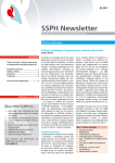
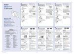
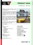
Temperature Chamber Series
CAT.NO.E94190-Q1407
Ideal for numerous applications ranging from
high-temperature tests to drying and heat processing.
The "Perfect Oven" epitomizes the features and performance of the ideal oven.
It is a versatile product, conducting high-temperature tests, but also drying and
heat treatment for production lines, with unrivaled reliability and performance.
The 56 models offered by ESPEC precisely answers the various needs of our customers.
1
2
MODEL VARIATION
+ 200℃/+ 300℃
PV
(H)
(+ 392°F /+ 572°F)
Temperature Chamber(Vertical type)
+ 200℃/+ 300℃
PH
(H)
(+ 392°F /+ 572°F)
Temperature Chamber(Horizontal type)
+ 500℃
STPH
(+ 932°F)
Ultra-High Temperature Chamber
+ 700℃
SSPH
(+1292°F)
Ultra-High Temperature Chamber
OVEN SERIES FOR VARIOUS APPLICATIONS
ST
(H)
DESK-TOP TYPE
HIGH-TEMP CHAMBER
+200℃/+300℃
15L/28L/39L
3
VAC
VACUUM OVEN
+200℃
933×102 to 1×10² Pa
LC
LCV
CONVECTION OVEN
VACUUM OVEN
+200℃/+250℃
90L/165L/360L
+200℃
0 to −101kPa(Gauge)
+ 200℃/+ 300℃
SPH
(H)
(+ 392°F /+ 572°F)
Temperature Chamber with Explosion Vent
+ 200℃/+ 300℃
IPH
(H)
(+ 392°F /+ 572°F)
Anaerobic Temperature Chamber
+ 200℃/+ 300℃
GPH
(H)
(+ 392°F /+ 572°F)
Temperature Chamber with Rotating Specimen Rack
PV
(H)
C
CLEAN OVEN
+200℃/+300℃/+350℃
178L/380L/678L
Class 5
(H)
LKS
LARGE VOLUME
TEMPERATURE CHAMBER
+200℃/+300℃
2250L/4050L
4
Control operation
Two types of program instrumentation to suit different applications.
Standard Instrumentation and M-Instrumentation.
User-friendly Standard
Instrumentation
Standard Inst r umentation feat u res
programmed operation with operational
settings such as constant mode and
automatic start/stop. Suitable for heat
treatment, drying, and similar productionline applications.
M-Instrumentation features
programs with up to 20 steps
Suitable for a range of applications from
temperature-characteristics testing to
heat treatment and drying. Programmed
operation now allows storing ten patterns,
each up to twenty steps. Provides a wide
range of functions, including temperature
ramp settings and a maximum of 999
repeat cycles.
Easy setup with on-screen
display
● Constant operation mode
Employs interactive settings for ease of
use. Text can be displayed and entered
in Japanese or English alphanumeric
characters.
Four optional functions
Four optional functions, namely, air flow
adjuster, automatic damper, integrating
hour meter, and calendar timer can be
included in the instrumentation. These
functions can be set by using main panel
instrumentation keys.
● Alarm
Interface (Option)
Interface for device communication can
be selected between RS-485, GPIB and
RS-232C.
5
Control operation
Examples of Programmed Operation
(M-Instrumentation)
Temperature Indicator-controller
Instrumentation Standard Instrumentation
Temp.
Operation mode
③
Step
program*
②
①
⑦…⑳
④
⑤
⑥
Time
Setting and
indication
ranges
M-Instrumentation
Constant operation, programmed operation and
remote operation through communication interface
Temperature:0 to+210℃ (+32 to +410°F)
0 to+310℃ (+32 to +590°F)
0 to+510℃ (+32 to +950°F)
0 to+710℃ (+32 to +1310°F)
Time: 0 to 9999 hours 59 minutes
Temp.
③
Ramp
program*
⑦…⑳
②
④
Setting
resolution
One-pattern, two-steps
10-patterns, 20-steps
program entry is possible. program entry is possible.
⑥
⑤
①
Time
Temp.
Automatic
start*
⑦…⑳
Programming
function
②
①
Time
1.HOLD
Temp.
End of
program
(selection)
⑥
③
2.CONST
Temp.
END
Time
Temperature at
the final step is
maintained.
3.OFF
Temp.
END
Time
Operation at
preset constant
temperature.
Temperature: 1℃ Time: 1 minute
END
Ramp setting:
Step or ramp temperature changes possible.
OFF mode:
The oven can be turned off during
programmed operation.
Automatic start:
Timed start-up is possible by setting
the first step to 0℃ (i.e. oven OFF).
Automatic stop:
Timed termination is possible by setting
the oven to turn OFF upon completion of
a program.
End mode:
The operating status upon completion of
a program can be set to
HOLD, CONST or OFF.
Repetition:
Up to 999 times.
Time
Oven is
turned OFF
* The number of repetitions of a program can be preset between 1 and 999.
Stepwise damper setting is possible using an optional automatic damper.
Guarantee soak function, whereby the timer is used to maintain a preset temperature
for a preset length of time, can also be performed.
Auxiliary
functions
Input burnout detection
Upper and lower temperature limit alarm
Upper deviation limit temperature alarm
Buzzer alarm
Automatic overheat protection
Trouble indication
Alarm indication
Self-diagnostic
Guarantee soak
Power failure recovery selection
Power failure protection
Quick timer
Quick operation
6
PV(H)
+ 200℃/+ 300℃
TEMPERATURE CHAMBER (Vertical type)
*Cable port and N2 gas injector are options.
A space-saving upright chamber
Components are incorporated into the top portion of
the vertical chamber, reducing installation space by
20~60% (comparison with conventional model).
Increases productivity on the production line, and
saves laboratory space.
Seamless door interior structure
Door back is a single molded structure preventing
heat losses from loose joints.
Large processing capacity
Since the f loor and shelves of the chamber have
b e e n g r e at ly r ei n for c e d , a l a r ge a mou nt of
specimens can be loaded and processed at the same
time. The sliding shelves ensure easy handling of
the specimens.
Excellent heating performance
Test area
7
Heating performance is greatly enhanced so that the
chamber temperature remains constant even if the
ventilation damper is opened. ( at +20℃ ambient
temperature)
SPECIFICATIONS
Model
PV−212
PV−222
PV−232
System
Performance *1
PVH−212
PVH−222
PVH−232
PVH−332
Ambient temp. +20℃ (+68°F) to +200℃ (+392°F)
Ambient temp. +20℃ (+68°F) to +300℃ (+572°F)
Temperature
fluctuation *2
±0.2℃ at +100℃ (+212°F), +200℃ (+392°F)
±0.2℃ at +100℃ (+212°F), +200℃ (+392°F),
±0.3℃ at +300℃ (+572°F)
Temperature
uniformity *2
±1.0℃ at +100 (+212°F), ±2.0℃ at +200℃ (+392°F)
±1.0℃ at +100℃ (+212°F), ±2.0℃ at +200℃ (+392°F),
±3.0℃ at +300℃ (+572°F)
Temperature
heat-up time
Ambient temp. to +200℃ (+392°F)
within 40 min.
Ambient temp. to +300℃ (+572°F)
within 60 min.
Temperature range *2
Construction
PV−332
Forced hot-air circulation / ventilation system
Exterior material
Cold rolled rust-proof steel plate, Melamine resin coating
Interior material
Stainless steel plate
Insulation material
Glass wool
Heater
Sheathed heater
Air circulator
Stainless steel sirocco fan
Damper
Circulation/ Ventilation (manual switching)
Power cable (approx 2m from chamber), Specimen power supply control terminals
(relay contact is opened/stop during malfunction. Voltage capacity 250V AC 3A)
Fittings
Inside dimensions W×H×Dmm (in)
600×600×600 600×900×600 600×1200×600 800×1200×800 600×600×600 600×900×600 600×1200×600 800×1200×800
(23.6×23.6×23.6) (23.6×35.4×23.6) (23.6×47.2×23.6) (31.5×47.2×31.5) (23.6×23.6×23.6) (23.6×35.4×23.6) (23.6×47.2×23.6) (31.5×47.2×31.5)
Outside dimensions *3
W×H×Dmm (in)
770×1200×925 770×1500×925 770×1800×925 1030×1800×1145 770×1200×925 770×1500×925 770×1800×925 1030×1800×1145
(30.3×47.2×36.4) (30.3×59×36.4) (30.3×70.9×36.4) (40.6×70.8×45.1) (30.3×47.2×36.4) (30.3×59×36.4) (30.3×70.9×36.4) (40.6×70.8×45.1)
Capacity (L)
216
324
432
768
216
324
432
768
Weight (kg)
165
190
210
325
165
190
210
325
Temperature: 0 to +40℃ (+32 to +104°F)
Utility requirements
Allowable ambient conditions
Humidity: to 75%rh
Power supply
200 / 220 / 230 / 240V AC
(Voltage fluctuation:
1φ 50/60Hz
±10% of rated value)
200 / 220V AC
200 / 220 /
3φ 3W 50/60Hz
230 / 240V AC
380V AC
1φ 50/60Hz
─
3φ 4W 50Hz
Max. power consumption
(kVA)
5.8
4.0
4.8
6.8
4.0
200 / 220V AC 3φ 3W 50/60Hz
380V AC
3φ 4W 50Hz
─
5.8
6.2
8.8
*1Values assume circulatory operation with no specimens at an ambient temperature of +23℃ ±5.
*2Conforms to Japan Testing Machinery standard K05:2000.
*3Excluding protrusions.
Shelf pitch, quantity and load resistance
Model
Shelf
pitch
Shelves
PV(H)-212
PV(H)-222
11
50mm
17
80mm
14
PV(H)-232
PV(H)-332
SAFETY DEVICES
Shelf load
Chamber total
resistance *1 *2 load resistance *1
Leakage breaker
Electrical compartment door switch
Door switch
Thermal fuse
Temperature switch for air circulator
Heater wiring breaker
Upper and lower temperature limit alarm
(built inside temperature controller)
Overheat protector
Cartridge fuse
Specimen power supply control terminal
●
●
25kg
23
●
200kg
●
●
45kg
●
*1Including shelf weight
*2Equally distributed load
●
●
ACCESSORIES
●
●
Shelf (stainless steel wire)
(stainless steel plate for type 332)
Shelf bracket (stainless steel)
Cartridge fuse
User's manual
●
2
●
2 sets (4)
2
1 set
●
●
8
PH(H)
+ 200℃/+ 300℃
TEMPERATURE CHAMBER (Horizontal type)
*N2 gas injector unit is option.
High performance chamber
A temperat u re -i ndicat ion cont roller with an
a dva nc e d PI D o p e r at ion , a nd a n or ig i n a l ly
d e ve l o p e d c h a m b e r c o n f ig u r a t i o n p r ov i d e
u n m a t ch e d ove n per for ma nce. Temperat u re
uniformity, temperature constancy, temperature
heat-up rate, and temperature recovery time are
performed with the upmost reliability.
Safety measures
Tr iple safet y me ch a n ism s a re e mploye d for
excessive overheating.
Test area
We provide a total of 16 ovens with combination of
temperature range, capacity, and instrumentation.
Energy Saver Duct
Standard
Energy Saver Duct
PH-201
Damper open 50%
Energy save
approx.
%
SET 200℃
23
Energy save
approx.
%
SET 100℃
19
0
9
0.5
Wide model selection
1
1.5
2
2.5
3
(kWh)
Energy Saver Duct (Option)
Energy saving approximately 20% by heat recycling
f r om ex h au s t t h r ou g h t he d uc t t o m a i nt a i n
temperature while damper opens.
SPECIFICATIONS
Model
PH−102
PH−202
PH−302
System
Performance *1
Temperature range *2
PHH−102
Ambient temp. +20℃ (+68°F) to +200℃ (+392°F)
PHH−202
PHH−302
PHH−402
Ambient temp. +20℃ (+68°F) to +300℃ (+572°F)
Temperature
fluctuation *2
±0.1℃ at +100℃ (+212°F) ±0.2℃ at +100℃ (+212°F)
±0.1℃ at +100℃ (+212°F) ±0.2℃ at +100℃ (+212°F)
±0.2℃ at +200℃ (+392°F) ±0.4℃ at +200℃ (+392°F)
±0.2℃ at +200℃ (+392°F) ±0.4℃ at +200℃ (+392°F)
+300℃ (+572°F) ±0.6℃ at +300℃ (+572°F)
Temperature
uniformity *2
±0.5℃ at +100℃ (+212°F) ±1.0℃ at +100℃ (+212°F)
±0.5℃ at +100℃ (+212°F) ±1.0℃ at +100℃ (+212°F)
±1.5℃ at +200℃ (+392°F) ±2.0℃ at +200℃ (+392°F)
±1.5℃ at +200℃ (+392°F) ±2.0℃ at +200℃ (+392°F)
±2.5℃ at +300℃ (+572°F) ±3.0℃ at +300℃ (+572°F)
Ambient temp. to +200℃ (+392°F)
Temperature
heat-up time
Construction
PH−402
Forced hot-air circulation / ventilation system
within 40 min.
Ambient temp. to +300℃ (+572°F)
within 60 min.
within 60 min.
Exterior material
Cold rolled rust-proof steel plate, Melamine resin coating
Interior material
Stainless steel plate
Insulation material
within 70 min.
Glass wool
Heater
Iron chrome strip wire heater
Air circulator
Stainless steel propeller fan
Damper
Circulation/ Ventilation (manual switching)
Power cable (approx 2m from chamber), Specimen power supply control terminals
(relay contact is opened/stop during malfunction. Voltage capacity 250V AC 3A)
Fittings
Inside dimensions W×H×Dmm (in)
450×450×450 600×600×600 800×800×800 1000×1000×1000 450×450×450 600×600×600 800×800×800 1000×1000×1000
(17.7×17.7×17.7) (23.6×23.6×23.6) (31.5×31.5×31.5) (39.4×39.4×39.4) (17.7×17.7×17.7) (23.6×23.6×23.6) (31.5×31.5×31.5) (39.4×39.4×39.4)
Outside dimensions *3
W×H×Dmm (in)
1040×820×635 1190×970×785 1500×1210×1065 1730×1480×1275 1040×820×635 1190×970×785 1500×1210×1065 1730×1480×1275
(41×32.3×25) (46.9×38.2×30.9) (59.1×47.6×41.9) (68.1×58.3×50.2) (41×32.3×25) (46.9×38.2×30.9) (59.1×47.6×41.9) (68.1×58.3×50.2)
Capacity (L)
91
216
512
1000
91
216
512
1000
Weight (kg)
95
130
240
430
95
130
240
430
Temperature: 0 to +40℃ (+32 to +104°F)
Utility requirements
Allowable ambient conditions
Power supply
200 / 220 / 230 / 240V AC
(Voltage fluctuation:
1φ 50/60Hz
±10% of rated value)
Max. power consumption
(kVA)
2.0
2.7
200 / 220V AC
3φ 3W 50/60Hz,
380V AC 3φ 4W 50Hz
5.0
Humidity: to 75%rh
200 / 220 / 230 / 240V AC
1φ 50/60Hz
6.5
2.7
3.8
200 / 220V AC
3φ 3W 50/60Hz,
380V AC 3φ 4W 50Hz
6.5
9.5
*1Values assume circulatory operation with no specimens at an ambient temperature of +23℃ ±5.
*2Conforms to Japan Testing Machinery standard K05:2000.
*3Excluding protrusions.
Shelf pitch, quantity and load resistance
Model
PH(H)-102
PH(H)-202
PH(H)-302
Shelf
pitch
SAFETY DEVICES
Shelf load
Chamber total
Shelves
resistance *1 *2 load resistance *1
50mm
8
11
80mm
9
PH(H)-402 140mm
6
20kg
40kg
50kg
Leakage breaker
Electrical compartment door switch
Door switch (type 402 only)
Thermal fuse
Temperature switch for air circulator (except type 402)
Air circulator overload relay (type 402 only)
Heater wiring breaker
Reverse-prevention relay
Upper and lower temperature limit alarm
(built inside temperature controller)
Overheat protector
Cartridge fuse
Specimen power supply control terminal
●
●
●
60kg
●
100kg
●
*1Including shelf weight
*2Equally distributed load
●
●
●
●
ACCESSORIES
●
Shelf (stainless steel wire for type102・202)2
(stainless steel punched plate for type 302・402)2
Shelf bracket (stainless steel)
2 sets (4)
Cartridge fuse
2
User's manual
1 set
●
●
●
●
●
●
10
+ 500℃
STPH
ULTRA-HIGH TEMPERATURE CHAMBER
Temperature control to +500℃
Effective temperature range of (ambient temp. +) 20℃
to +500℃ . The chamber can be used for a variety of
applications, including tests of viability under hightemperatures and temperature resistance.
Door equipped with a single-action
lever
The door can be firmly locked by an easy-to-use
single-action lever. It prevents accidents from
unlocked doors.
SPECIFICATIONS
Model
Performance *1
System
STPH-202
Forced hot-air circulation / ventilation system
Temp. range *2
Ambient temp.+20℃ (+68°F) to +500℃ (+932°F)
Temp. fluctuation *2
±0.5℃
Temp.
uniformity *2
Temp.
heat-up time
Construction
STPH-102
±0.8℃ at +100℃ (+212°F)
±1.8℃ at +200℃ (+392°F)
±2.8℃ at +300℃ (+572°F)
±3.8℃ at +400℃ (+752°F)
±4.8℃ at +500℃ (+932°F)
Ambient temp.
to +500℃ (+932°F) within 60min.
Interior
Stainless steel plate
Insulation
Glass wool, MG wool
ACCESSORIES
Shelf (stainless steel wire)
Shelf bracket (stainless steel)
Cartridge fuse
User's manual
●
●
●
●
SAFETY DEVICES
Heater
Iron chrome strip wire heater
Air circulator
Stainless steel propeller fan
●
Circulation/ Ventilation (manual switching)
●
Damper
Fittings
Power cable (approx 2m from chamber),
Specimen power supply control terminals
Electrical compartment cooling fan
Inside dimensions
W×H×Dmm (in)
450×450×450
(17.7×17.7×17.7)
600×600×600
(23.6×23.6×23.6)
Outside dimensions
W×H×Dmm (in) *3
1190×1110×795
(46.9×43.7×31.3)
1340×1260×945
(52.8×49.6×37.2)
Capacity (L)
91
216
Weight (kg)
190
250
Leakage breaker
Electrical compartment door switch
Thermal fuse
Temperature switch for air circulator
Electrical compartment thermal switch
Heater wiring breaker
Upper and lower temperature limit alarm
(built inside temperature controller)
Overheat protector
Cartridge fuse
Specimen power supply control terminal
●
●
●
●
Utility requirements
Allowable ambient
conditions
Temp.: 0 to +40℃ (+32 to +104°F)
Humid.: to 75%rh
Power supply
(±10% of rated value)
200 / 220V AC 3φ 50/60Hz,
380V AC 3φ 4W 50Hz
Max. power
consumption
6.5 kVA
8.3 kVA
*1Values assume circulatory operation with no specimens at an ambient
temperature of +23℃ ±5.
*2Conforms to Japan Testing Machinery standard K05:2000.
*3Excluding protrusions.
11
●
●
●
●
2
2 sets (4)
2
1 set
+ 700℃
SSPH
ULTRA-HIGH TEMPERATURE CHAMBER
Saving-energy insulated structure
Ceramic fiber and aluminium foil are used as
insulation materials. It increases effective insulation
and prevents heat loss, thus saving energy.
A Double seal gasket configuration
A gasket made of stainless steel fiber and a leaf
spring are used to form a double seal between the
door and the chamber. Prevents heat radiation on
door.
Door equipped with a single-action lever
The door can be firmly locked by an easy-to-use
single-action lever.
SPECIFICATIONS
Model
System
Performance *1
Temp. range *2
Shelf (stainless steel wire)
Shelf bracket (stainless steel)
Cartridge fuse
User's manual
●
●
●
●
2
2 sets (4)
2
1 set
Interior
SAFETY DEVICES
Leakage breaker
Electrical compartment door switch
Thermal fuse
Temperature switch for air circulator
Air circulator rotation detector
Electrical compartment thermal switch
Heater wiring breaker
Upper and lower temperature limit alarm
(built inside temperature controller)
Overheat protector
Cartridge fuse
Specimen power supply control terminal
●
Temp.
uniformity *2
Temp.
heat-up time
Construction
ACCESSORIES
Temp.
fluctuation *2
Insulation
Heater
Air circulator
Damper
SSPH-202
Forced hot-air circulation / ventilation system
+100 to +700℃ (+212 to +1292°F)
±0.5℃ at +100 to +500℃ (+212 to +932°F)
±0.8℃ at +501 to +700℃ (+933 to +1292°F)
±0.8℃ at +100℃ ( +212°F)
±2.8℃ at +300℃ ( +572°F)
±4.8℃ at +500℃ ( +932°F)
±7.0℃ at +700℃ (+ 1292°F)
Ambient temp. to +700℃ (+1292°F)
within 120min.
within 160min.
Stainless steel plate
Glass wool, Ceramic fiber
Iron chrome strip wire heater
Stainless steel propeller fan
Circulation/ Ventilation (manual switching)
Fittings
Power cable (approx 2m from chamber),
Specimen power supply control terminals
Electrical compartment cooling fan
Inside dimensions
W×H×Dmm (in)
450×450×450
(17.7×17.7×17.7)
600×600×600
(23.6×23.6×23.6)
Outside dimensions
W×H×Dmm (in) *3
1190×1110×795
(46.9×43.7×31.3)
1340×1260×945
(52.8×49.6×37.2)
Capacity (L)
91
216
Weight (kg)
250
330
●
●
SSPH-102
●
●
●
●
●
●
●
Utility requirements
●
Allowable ambient
conditions
Temp.: 0 to +40℃ (+32 to +104°F)
Humid.: to 75%rh
Power supply
(±10% of rated value)
200 / 220V AC 3φ 50/60Hz,
380V AC 3φ 4W 50Hz
Max. power
consumption
8.3 kVA
9.5 kVA
*1Values assume circulatory operation with no specimens at an ambient
temperature of +23℃ ±5.
*2Conforms to Japan Testing Machinery standard K05:2000.
*3Excluding protrusions.
12
SPH(H)
+ 200℃/+ 300℃
TEMPERATURE CHAMBER WITH EXPLOSION VENT
Temperature chamber
with Explosion Vent
This temperature chamber is suitable for drying and
heat-treatment of f lammable synthetic resins or
volatile solvents. It is equipped with an explosion
vent which releases explosion and a safety door to
ensure security.
Door equipped
with a single-action lever
The door can be securely locked by an easy-to-use
single-action lever. Even if the operator accidentally
turns on the power when door is unlocked, the door
lock detection switch prevents heater fan from
starting. Besides, in three minutes, the alarm buzzer
sounds to call for warning.
WARNING
1) The following flammables or materials containing them
can be subjected to drying (heat treatment) with this
chamber. However, to avoid explosion, ventilate the
chamber well and use the chamber below the
explosive limit.
注意
Inflammables:
●
●
Ignitable Substances
1. Ethyl ether, gasoline, acetaldehyde, propylene oxide,
carbon disulfide, carbon dioxide and other
substances with an ignition point of below−30℃ .
2. Normal hexane, ethylene oxide, acetone, benzene,
methyl ethyl ketone and other substances with an
ignition point above −30℃ and below 0℃ .
3. Methanol, ethanol, xylene, pentyl acetate
amylacetate and other substances with an ignition
point above 0℃ and below +30℃ .
4. Kerosene, light oil, turpentine oil, isopentyl alcohol
(also called isoamyl alcohol), acetic acid and other
substances with an ignition point above +30℃ and
below +65℃ .
●
Combustible Gases
Hydrogen, acetylene, ethylene, methance, ethane,
propane, butane, and other combustible substances
that are in a gaseous state at a temperature of +15℃
and at a pressure of 1 atmosphere.
Release explosion safely
Aluminium plate
Insulation material
Flame
Specimen
Explosion
In case an explosion occurs inside the test chamber, as shown
in the above image, insulation material is bent and blown
upward together with the aluminium plate to the metal screen
at the top of the chamber.
This way the explosion is safely channeled and released
through the top metal screen. For SPH(H)-402, explosion is
released through the top metal screen by bending insulation
material on the rear wall.
■Release explosion safely
13
In the event that an explosion occure inside the test chamber, as
shown in the below figures, insulation material is bent and blown
upward together with the aluminium plate to the metal screen at
the top of the chamber.
2) Temperature chamber with explosion vent is fitted with
a comprehensive range of devices to ensure safety. In
addition to the regular inspection, these must be
carefully inspected before reusing after an explosion.
3) This equipment is designed to prevent any damage to
people or equipment in the vicinity for explosion
pressures not exceeding 29.4kPa. If the explosion
pressure exceeds 9.8kPa, reuse of the equipment
itself may not be possible.
4) Please refer to the instruction manual before using the
chamber to ensure safe operation.
SPECIFICATIONS
Model
SPH−102
SPH−202
System
Performance *1
Temperature range *2
SPH−402
SPHH−102
SPHH−202
SPHH−302
SPHH−402
Forced hot-air circulation / ventilation system
Ambient temp. +20℃ (+68°F) to +200℃ (+392°F)
Ambient temp. +20℃ (+68°F) to +300℃ (+572°F)
Temperature
fluctuation *2
±0.1℃ at +100℃ (+212°F) ±0.2℃ at +100℃ (+212°F)
±0.1℃ at +100℃ (+212°F) ±0.2℃ at +100℃ (+212°F)
±0.2℃ at +200℃ (+392°F) ±0.4℃ at +200℃ (+392°F)
±0.2℃ at +200℃ (+392°F) ±0.4℃ at +200℃ (+392°F)
±0.2℃ at +300℃ (+572°F) ±0.6℃ at +300℃ (+572°F)
Temperature
uniformity *2
±0.5℃ at +100℃ (+212°F) ±1.0℃ at +100℃ (+212°F)
±0.5℃ at +100℃ (+212°F) ±1.0℃ at +100℃ (+212°F)
±1.5℃ at +200℃ (+392°F) ±2.0℃ at +200℃ (+392°F)
±1.5℃ at +200℃ (+392°F) ±2.0℃ at +200℃ (+392°F)
±2.5℃ at +300℃ (+572°F) ±3.0℃ at +300℃ (+572°F)
Ambient temp. to +200℃ (+392°F)
Temperature
heat-up time
Construction
SPH−302
within 40 min.
Ambient temp. to +300℃ (+572°F)
within 60 min.
within 60 min.
Exterior material
Cold rolled rust-proof steel plate, Melamine resin coating
Interior material
Stainless steel plate
Insulation material
within 70 min.
Glass wool
Safety vent to release inside pressure on explosion,
Explosion exhaust duct, Protective wire mesh, Insulation, Outer plate
Explosion vent
Stainless steel, Sheated heater with fin
Heater
Air circulator
Stainless steel propeller fan
Damper
Circulation/ Ventilation (manual switching)
Power cable (approx 2m from chamber), Specimen power supply control terminals
(relay contact is opened/stop during malfunction. Voltage capacity 250V AC 3A).
Fittings
Inside dimensions W×H×Dmm (in)
450×450×450 600×600×600 800×800×800 1000×1000×1000 450×450×450 600×600×600 800×800×800 1000×1000×1000
(17.7×17.7×17.7) (23.6×23.6×23.6) (31.5×31.5×31.5) (39.4×39.4×39.4) (17.7×17.7×17.7) (23.6×23.6×23.6) (31.5×31.5×31.5) (39.4×39.4×39.4)
Outside dimensions *3
W×H×Dmm (in)
1040×1260×635 1190×1370×785 1500×1715×1065 1730×1800×1775 1040×1260×635 1190×1370×785 1500×1715×1065 1730×1800×1775
(41×49.6×25) (46.9×53.9×30.9) (59.1×68.1×41.9) (68.1×70.9×69.9) (41×49.6×25) (46.9×53.9×30.9) (59.1×68.1×41.9) (68.1×70.9×69.9)
Capacity (L)
91
216
Weight (kg)
95
130
Utility requirements
1000
91
270
500
95
Temperature: 0 to +40℃ (+32 to +104°F)
Allowable ambient conditions
Power supply
200 / 220 / 230 / 240V AC
(Voltage fluctuation:
1φ 50/60Hz
±10% of rated value)
Max. power consumption
(kVA)
512
2.0
2.7
200 / 220V AC
3φ 3W 50/60Hz,
380V AC 3φ 4W 50Hz
5.0
216
512
1000
130
270
500
Humidity: to 75%rh
200 / 220 / 230 / 240V AC
1φ 50/60Hz
6.5
2.7
3.8
200 / 220V AC
3φ 3W 50/60Hz,
380V AC 3φ 4W 50Hz
6.5
9.5
*1Values assume circulatory operation with no specimens at an ambient temperature of +23℃ ±5.
*2Conforms to Japan Testing Machinery standard K05:2000.
*3Excluding protrusions.
ACCESSORIES
SAFETY DEVICES
Shelf(stainless steel wire for type 102・202)2
(stainless steel punched plate for type 302・402)2
●
Shelf bracket (stainless steel)
Cartridge fuse
Protective wire mesh
(stainless steel mesh with soft aluminium foil)
2 sets (4)
2
1
Insulation (glass wool)
Outer plate (thin soft aluminium panel)
Stand bracket and hexagon socket head cap screw (for type 102・202)
3
1
4 each
●
●
●
●
●
●
●
●
●
●
●
●
Hexagon socket screw key (for type 102・202)1
1 set
User's manual
●
Leakage breaker
Electrical compartment door switch
Chamber door lock detection switch
Explosion detection limit switch
Thermal fuse
Temperature switch for air circulator (except type 402)
Air circulator overload relay (for type 402 only)
Heater wiring breaker
Reverse-prevention relay (for type 402 only)
Upper and lower temperature limit alarm
(built inside temperature controller)
Overheat protector
Cartridge fuse
Specimen power supply control terminal
●
●
●
●
●
●
●
●
14
IPH(H)
+ 200℃/+ 300℃
ANAEROBIC TEMPERATURE CHAMBER
Low oxygen level testing
Equipped with a non-oxidizing gas intake structure
which fills the chamber with non-oxidizing gas such
as CO 2 or N 2 for heat treatment or temperature
character istics testi ng requi r i ng low oxygen
concentration atmosphere.
Hermetically sealed configuration
The chamber is hermetically sealed to decrease oxygen
inside the chamber. The inner stainless steel plate is
seamless welded with argon gas.
O2 concentration indicator controller (optional)
An optional O2 concentration indicator controller
equipped with an oxygen sensor is available. It
allows precise regulation of the O2 level throughout
the range 0.5 to 21% (using N2).
SPECIFICATIONS
Model
System
Performance *1
Temp. range *2
Temp.
fluctuation *2
Temp.
uniformity *2
Temp.
heat-up time
IPHH−202
Fluid
CO2, N2 gas (ordinary temperature, dry gas)
Fluid pressure
Allowed max. pressure: 2.0MPa (Gauge) (primary side of valve)
Secondary side is adjusted with the valve to 0.05MPa (Gauge)
Flow rate
Gas intake unit
IPH−202
Forced hot-air circulation system
Ambient temp. +20℃ (+68°F) Ambient temp. +20℃ (+68°F)
to +200℃ (+392°F)
to +300℃ (+572°F)
±0.1℃ at +100℃ (+212°F)
±0.1℃ at +100℃ (+212°F)
±0.2℃ at +200℃ (+392°F)
±0.2℃ at +200℃ (+392°F)
±0.2℃ at +300℃ (+572°F)
±0.1℃ at +100℃ (+212°F)
±0.5℃ at +100℃ (+212°F)
±0.2℃ at +200℃ (+392°F)
±1.5℃ at +200℃ (+392°F)
±0.2℃ at +300℃ (+572°F)
Ambient temp. to +200℃ Ambient temp. to +300℃
(+392°F) within 40min.
(+572°F) within 60min.
Chamber O2 level
Chamber injector pressure
Valve
Pressure gauge
Flow meter
Max. flow rate: 20 L / min. (0.05MPa (Gauge), 20℃)
ACCESSORIES
Shelf (stainless steel wire)
Shelf bracket (stainless steel)
●
0.5% (lowest)
●
29Pa (Gauge) and over (at max flow rate)
●
1/4" brass needle valve
●
Cartridge fuse
User's manual
φ75mm embedded type class 2.5
Scale range: 0 〜 0.1MPa (Gauge)
Floating type (provided with needle valve for flow rate control)
Scale range
0 to 30L / min. N2 gas
Safety valve
Trip pressure: 2.0kPa (Gauge)
SAFETY DEVICES
Leakage breaker
Electrical compartment door switch
Thermal fuse
Temperature switch for air circulator
Heater wiring breaker
Upper and lower temperature limit alarm
(built inside temperature controller)
Overheat protector
Cartridge fuse
Specimen power supply control terminal
●
Gas inlet
Fittings
1/4" ring joint
Power cable (approx 2m from chamber),
Specimen power supply control terminal
●
Inside dimensions (in) W600mm×H600mm×D600mm (23.6×23.6×23.6)
●
Outside dimensions (in) *3
W1190mm×H970mm×D785mm (46.9×38.2×30.9)
●
Capacity (L)
216
●
Weight (kg)
130
Utility
requirements
Allowable ambient conditions Temp.: 0 to +40℃ (+32 to +104°F) Humid.: to 75%rh
15
●
Power supply
(±10% of rated value)
Max. power consumption
200 / 220 / 230 / 240V AC 1φ 50/60Hz
2.7 kVA
3.8 kVA
*1Values assume circulatory operation with no specimens at an ambient temperature of +23℃ ±5.
*2Conforms to Japan Testing Machinery standard K05:2000.
*3Excluding protrusions.
●
●
●
2
2 sets (4)
2
1 set
GPH(H)
+ 200℃/+ 300℃
TEMPERATURE CHAMBER WITH ROTATING SPECIMEN RACK
Suitable for heat deterioration test
Based on the PH Temperature Chambers, these
models incorporate a detachable rotating specimen
rack and is especially designed for heat deterioration
testing of rubbers and plastics including polyesters
and vinyls.
Equipped with a rotating specimen rack
The rack drive unit is installed inside, enhancing
function and lending them a simple appearance.
By removing the rack, this equipment may also be
operated as an ordinary temperature chamber.
SPECIFICATIONS
GPH−102 GPH−202 GPHH−102 GPHH−202
Model
System
Performance *1
Temp.range
Forced hot-air circulation / ventilation system
*2
Temp. fluctuation *2
Temp.uniformity *2
Specimen rack rotating unit
Temp.heat-up time
Number of racks
Ambient temp. +20℃ (+68°F) Ambient temp. +20℃ (+68°F)
to +200℃ (+392°F)
to +300℃ (+572°F)
±0.1℃ at +100℃ (+212°F)
±0.1℃ at +100℃ (+212°F)
±0.2℃ at +200℃ (+392°F)
±0.2℃ at +200℃ (+392°F)
±0.2℃ at +300℃ (+572°F)
±0.5℃ at +100℃ (+212°F)
±0.5℃ at +100℃ (+212°F)
±1.5℃ at +200℃ (+392°F)
±1.5℃ at +200℃ (+392°F)
±2.5℃ at +300℃ (+572°F)
Ambient temp.
Ambient temp.
to +200℃ (+392°F) to +300℃ (+572°F)
within 40min.
within 60min.
1
2
Outside diameter
1
2
320mm (12.6in.)
Available numbers
of specimens/weight
Test area
56pcs per rack (up to 0.7kg)
Specimen clip
ACCESSORIES
50pcs per rack
RPM of specimen rack
5rpm/50Hz, 6rpm/60Hz
●
190×340(7.48×13.39)
————
Construction
Heat-resistant
reinforced glass
3-plate sets
————
Chamber lamp
5.5W
incandescent lamp
————
Fittings
Power cable (approx 2m from chamber),
Specimen power supply control terminals
(relay contact is opened during malfunction.
Voltage capacity 250V AC 3A)
Viewing
window
W×Hmm (in)
Inside dimensions W×H×Dmm (in)
2
Shelf (stainless steel wire)
bracket
(stainless
steel)
2
sets
(4)
Shelf
2
Cartridge fuse
50
Specimen cliptype102
type202100
1 set
Shaft insulation filters
1 set
User's manual
●
1φ 15W
Motor
●
●
●
450×450×450 600×600×600 450×450×450 600×600×600
(17.7×17.7×17.7) (23.6×23.6×23.6) (17.7×17.7×17.7) (23.6×23.6×23.6)
Outside dimensions *3 1040×820×635 1190×970×785 1040×820×635 1190×970×785
(91×32.3×25) (46.9×38.2×30.9) (91×32.3×25) (46.9×38.2×30.9)
W×H×Dmm (in)
●
SAFETY DEVICES
Leakage breaker
Electrical compartment door switch
Thermal fuse
Temperature switch for air circulator
Heater wiring breaker
Upper and lower temperature limit alarm
(built inside temperature controller)
Overheat protector
Cartridge fuse
Specimen power supply control terminal
●
●
●
●
Capacity (L)
91
216
91
216
Weight (kg)
95
130
95
130
●
Utility
requirements
Allowable ambient conditions Temp.: 0 to +40℃ (+32 to +104°F) Humid.: to 75%rh
Power supply
(±10% of rated value)
200 / 220 / 230 / 240V AC 1φ
50/60Hz
Max. power consumption 2.0 kVA
2.7 kVA
3.8 kVA
*1Values assume circulatory operation with no specimens at an ambient temperature of +23℃ ±5.
*2Conforms to Japan Testing Machinery standard K05:2000.
*3Excluding protrusions.
●
●
●
●
16
OPTIONS
IPH
GPH
GPHH
IPHH
212 222 232 332 102 202 302 402 102 202 102 202 102 202 302 402 202 102 202
Model PV
PH
PVH
Option
STPH
SSPH
SPH
SPHH
Time run-out output
●
●
●
●
●
●
●
●
●
●
●
●
●
●
●
●
●
●
●
Calendar timer
●
●
●
●
●
●
●
●
●
●
●
●
●
●
●
●
●
●
●
Integrating hour meter
●
●
●
●
●
●
●
●
●
●
●
●
●
●
●
●
●
●
●
Temperature recorder terminal
●
●
●
●
●
●
●
●
●
●
●
●
●
●
●
●
●
●
●
Paperless recorder/
Temperature recorder
●
●
●
●
●
●
●
●
●
●
●
●
●
●
●
●
●
●
●
Recorder wiring
●
●
●
●
●
●
●
●
●
●
●
●
●
●
●
●
●
●
●
Automatic damper
●
●
●
●
●
●
●
●
●
●
●
●
●
●
●
●
—
●
●
Exhaust port flange
●
●
●
●
●
●
●
●
●
●
●
●
●
●
●
●
—
●
●
Exhaust duct
●
●
●
●
●
●
●
—
●
●
●
●
●
●
●
—
—
●
●
Energy Saver Duct
—
—
—
—
●
●
—
—
—
—
—
—
●
●
—
—
—
●
●
Nitrogen gas injector
●
●
●
●
●
●
●
●
●
●
●
●
—
—
●
●
—
—
—
—
—
—
—
—
—
—
—
●
●
—
—
—
—
—
—
—
—
—
—
—
—
—
—
—
—
—
—
Inert specification
—
—
—
—
350℃ Specification
—
—
—
—
—
—
—
—
●
●
●
● —
— — — — —
—
—
—
—
●
● —
— — —
●
—
—
Air flow adjuster
●
●
●
●
●
●
●
●
—
—
—
—
—
—
—
—
●
●
●
Fin heater
—
—
—
—
●
●
●
●
—
—
—
—
※
※
※
※
●
●
●
●
●
●
—
●
●
—
—
●
●
●
●
●
●
—
—
●
●
●
—
—
—
●
●
●
●
●
—
—
—
—
●
●
●
●
●
●
●
O2
concentration indicator-controller
18-8 Cr-Ni
stainless steel wire
Shelf
and
shelf
18-8 Cr-Ni
bracket punched stainless steel shelf
Mesh shelf
Vertical type
HeavyHorizontal type (25kg)
duty
shelf
Horizontal type (60kg)
Cable port
Cable port rubber plug
●
●
●
●
—
—
—
—
—
—
—
—
—
—
—
—
—
—
—
●
●
●
●
—
—
—
—
—
—
—
—
—
—
—
—
—
—
—
—
—
—
—
●
●
—
—
—
—
—
—
●
●
—
—
●
●
●
—
—
—
—
—
●
●
—
—
—
—
—
—
●
●
—
●
—
●
●
●
●
—
—
—
—
—
—
—
—
—
—
—
—
—
—
—
● ●
— ●— ●—
●
●
●
●
—
—
—
—
●
●
●
—
—
—
—
—
—
—
—
—
—
—
●
●
—
—
Casters
Viewing window
●
—
●
●
—
●
●
—
●
●
—
●
●
—
●
●
—
●
●
—
●
●
—
●
●
●
—
●
●
—
●
●
●
—
●
●
—
—
●
●
—
●
—
—
●
●
—
Chamber lamp
—
—
—
—
—
—
—
—
—
—
—
—
—
—
—
Anchoring fixtures
●
●
●
●
●
●
●
—
—
—
—
—
●
●
●
—
●
●
●
Floor reinforcement
—
—
—
—
—
●
●
●
—
—
—
—
—
●
●
●
●
—
●
Stand
—
—
—
—
Vertical type
●
●
—
—
—
—
—
—
—
—
—
—
—
—
—
—
—
—
—
Horizontal type
—
—
—
—
●
●
●
—
●
●
●
●
●
●
●
—
●
●
●
Angle type stand
—
—
—
—
—
—
—
●
—
—
—
—
—
—
—
●
—
—
—
Casters for stand
—
—
—
—
●
●
—
—
—
—
—
—
—
—
—
—
●
●
●
Stacking brackets
—
—
—
—
●
●
—
—
—
—
—
—
—
—
—
—
●
—
—
L-type-stand and stacking brackets —
—
—
—
●
●
—
—
—
—
—
—
—
—
—
—
●
—
—
External alarm terminal
●
●
●
●
●
●
●
●
●
●
●
●
●
●
●
●
●
●
●
Emergency stop pushbutton
●
●
●
●
●
●
●
●
●
●
●
●
●
●
●
●
●
●
●
Color specification
●
●
●
●
●
●
●
●
●
●
●
●
●
●
●
●
●
●
●
Interface
●
●
●
●
●
●
●
●
●
●
●
●
●
●
●
●
●
●
●
Power cable
●
●
●
●
●
●
●
●
●
●
●
●
●
●
●
●
●
●
●
※Standard specification
17
PHH
OPTIONS
Time run-out output
Temperature recorder terminal
Temperature recorder
This option enables turning the power
to the specimen ON or OFF with
contact signal output when the time is
up by using the timer function on the
controller.
Power supply rating: 250VAC 1A
Actuation: Contact close when
program time overflows
Where located: Right side of chamber
Outputs chamber temperature through
thermocouple type K (JIS C 1602)
(Thermocouple type N for STPH, SSPH)
Where located:
Rear of electrical compartment
Temp. range: 0 to +200℃
0 to +300℃
0 to +600℃
0 to +800℃
Recording system:
Pen recorder (1 pen)
or multi-point recorder (6 dots)
* If performing simultaneous installation of a
recorder and an N2 gas injector, they must be
handled individually. Otherwise, installation
may be limited depending on what other
options are chosen.
Paperless recorder
Calendar timer
Automatically starts and stops chamber
operation.
Setting range:
Sunday to Saturday
(Possible to set multiple days)
0:00 to 23:59
(Setting resolution 1 minute)
Margin of error per month: ±1 minute
Records temperature of each section
such as the temperature inside the
chamber.
Temp. range: 0〜+200℃
0〜+300℃
0〜+600℃
0〜+800℃
Number of inputs: Temperture 1
(5 more channels can be turned ON)
Data saving cycle: 5 sec
External recording media:
CF memory card port
(Includes a 256MB CFcard)
Language support: ENG, JPN
Temperature recorder wiring
Preparation of a power cable, temperature sensor and a grounding wire for
additional installation in the future.
Automatic damper
Automatically opens or closes
synchronously with program operation
for ventilation and faster cooling of
chamber temperature.
Integrating hour meter
Displays cumulative chamber operation
time.
Available with or without reset feature.
* Operating time is not accumulated when
operation is stopped due to malfunction or for
other reasons.
Measuring time: 999,999 hr
●Please refer to chart on p.17 for applicable models.
18
Energy save
approx.
%
SET 200℃
23
Energy save
approx.
%
SET 100℃
19
0
0.5
1
1.5
2
2.5
3
(kWh)
OPTIONS
Exhaust port flange
Energy Saver Duct
350℃ specification
Flange connects an exhaust duct to the
chamber to exhaust hot air from the
chamber.
(for oven with damper.)
Material:Cold rolled steel plate with
chromate conversion coatings
Stainless steel sheet
STPH-102, 202
SSPH-102, 202
Dimensions: External diameter 87mm
Location: Chamber rear side
Discharges exhaust air towards to
Standard
ceiling with
heat exchanger for energy
Energy Saver Duct
saving by
heat recycling.
Dimensions of exhaust port flange:
Standard
External diameter 87mm
Energy
Saver Duct
Location:
Chamber
rear side
Adapted to provide a maximum
temperature of 350℃.
*The height of chamber will be 30mm higher
than standard unit by the additional lower flame.
Exhaust
air
Intake
air
* When connecting to exhaust duct, the length of
duct must be less than 4m.
* PHH only.
O2 concentration indicator-controller
Controls oxygen concentration inside
the oven.
O2 concentration range:
0.5 to 21% oxygen concentration (v/v)
Gas: N2 gas
(ordinary temperature dry gas)
* IPH(H) only.
Nitrogen gas injector
Exhaust duct
Discharges hot air towards the ceiling.
(for oven with damper.)
Dimensions: External diameter 87mm
Location: Chamber rear side
* Exhaust port f lange is provided at end of
exhaust duct.
Used for reducing specimen oxidation.
Fluid pressure: Max. allowable pressure 2.0MPa (Gauge) on primary side of valve
0.05MPa(Gauge)on
secondary side using valve.
Max flow rate: 30 L min.
Flow meter: Float type flow meter
* If performing simultaneous installation of a
recorder and an N2 gas introducing unit, they
must be handled individually. Otherwise,
installation may be limited depending on what
other options are chosen.
Air flow adjuster
Allows low air velocity in chamber
PV(H)
0.3 to 2.3m/s
PH(H)-102/202
GPH(H)-102/202
0.2 to 2.3m/s
IPH(H)-202
PH(H)-302
0.3 to 2.3m/s
PH(H)-402
0.3 to 2.6m/s
Average wind velocity across
chamber central longitudinal
section. Represents the typical
mean value for each chamber.
Fin heater
Inert specification
Used to minimize the oxidation of
specimens.
* STPH only.
* Standard dampers are not fitted.
●Please refer to chart on p.17 for applicable models.
19
Used when anti-corrosive is required.
Stainless steel sheathed heater with fins.
OPTIONS
Shelf and shelf bracket
Heavy-duty shelf
Additional cable port
Equivalent to standard accessory.
PH(H)-102/202, SPH(H)-102/202,
GPH(H), and IPH(H) include stainless
steel punched plate that differs from the
standard shelf provided.
Used to hold heavy specimen exceeding
the load capacity of the standard shelf.
A through hole provided on the wall of
chamber.
Material: Stainless steel plate
Inside diameter: 25, 50, 100mm
(φ50mm for STPH-102・202)
* The cable port may not be able to be used at the
same time as the optional exhaust duct. (Except
when used with PV(H))
* If several cable ports are installed, the surface
temperature may rise or the chamber may not
be able to meet standard performance.
Stainless steel wire
<Vertical type>
Material: 18-8 Cr-Ni stainless steel wire
Shelf support load resistance: Max 200kg
Stainless steel punched plate
Model
Shelf load resistance*
PV(H)-212
-222
-232
45kg
PV(H)-332
90kg
*Uniformly distributed load
<Horizontal type>
For 25kg
Mesh shelf
For testing small specimens.
Material: 18-8 Cr-Ni stainless steel
φ0.8, 5 mesh
* To use, place this shelf on a standard shelf.
Material: 18-8 Cr-Ni stainless steel wire
Shelf support load resistance: Max 50kg
<Possible installation points>
Model
Top
Rear Left side right side
PV(H)
×
×
○
○
PH(H)102・202・302
○
○
○
×
PH(H)-402
×
○
○
×
GPH(H)
×
○
○
×
STPH(H)
×
○
×
×
* Equipped with 2 sets of shelf and shelf bracket.
For 60kg
Material: 18-8 Cr-Ni punched stainless steel
Shelf support load resistance: Max 200kg
* Standard shelves not provided.
Cable port rubber plug
Prevents airleakage from the cable port.
Inside diameter: 25, 50, 100mm
* This rubber plug cannot be used when operating
the chamber at +200℃ or higher.
Casters
Model
Size
Shelf load resistance*
PV(H)-212
-222
-232
W550×
D600×
H35 mm
10kg
PV(H)-332
W740×
D740×
H38 mm
15kg
*Uniformly distributed load.
Installed for mobility.
・Adjustable type (Height 92mm)
4 casters
4 leveling feet
・Non-adjustable type (Height 85mm)
2 casters with stoppers
2 fixed wheels
●Please refer to chart on p.17 for applicable models.
20
OPTIONS
Viewing window
Stand
Angle type stand
Used for observation of the specimens
inside the chamber.
Dimensions: W190×L340 mm
Exterior: Cold rolled and rust-proof
steel plate with melamine baked finish
Added to the chamber's original stand,
this stand makes it easier to load and
unload the specimen to the lower part
of the test chamber.
Exterior: Equal-angle steel
Melamine baked finish
<Vertical type>
Type
Top
MV-23
300mm
MV-23C
321mm
MV-26
600mm
Model
PV(H)-212・222
Type
Height
L
150mm
*Type C: Casters and leveling feet
M
300mm
*with door
H
450mm
MV-26C
621mm
PV(H)-212
Model
PH(H)-402
SPH(H)-402
Casters for stand
Attached to the optional stand.
・Height adjustable (Height 92mm)
Free-turning wheel 4
4
Leveling feet
Chamber lamp
Required when the door is fitted with
viewing windows.
Location (incandescent light bulb):
PH-102, 202-Test area ceiling
PH-302, 402-Test area rear wall
<Horizontal type>
MV-23C
<Horizontal type>
Type
Height
L-1
Anchoring fixtures
Floor reinforcement
Model
PH(H)-202, GPH(H)-202
IPH(H)-202
L-3
200mm
PH(H)-302, SPH(H)-302
M-1
365mm
PH(H)-102, GPH(H)-102
PH(H)-202, GPH(H)-202
IPH(H)-202
M-2
M-3
400mm
MS-1
STPH-102, SSPH-102
MS-2
STPH-202, SSPH-202
* This option should be ordered together with the
chamber.
H-1(D)
Floor load
resistance*
PH(H)-202
SaPH(H)-202
GPH(H)-202
IPH(H)-202
Up to 200kg
PH(H)-302
SPH(H)-302
PH(H)-402
SPH(H)-402
Up to 300kg
Standard load
resistance*
50kg
505mm
PH(H)-102, SPH(H)-102,
GPH(H)-102
H-2(D)
540mm
PH(H)-202, SPH(H)-202,
GPH(H)-202, IPH(H)-202
H-3(D)
585mm
PH(H)-302, SPH(H)-302
*Type(D): with door
60kg
100kg
* Equally distributed load
From the side, L-2,
M-2 (casters are optional) and H-2
● Please refer to chart on p.17 for applicable models.
■ Some photographs listed in this catalog contain Japanese display.
21
When stacking two chambers, this plate
couples the top and bottom chambers
securely.
*Only the L model optional stand can be used
when chambers are stacked.
PH(H)-302, SPH(H)-302
Used when testing load is larger than
standard maximum load capacity.
Model
Stacking brackets
PH(H)-102, GPH(H)-102
140mm
L-2
Used to bolt the chamber to the floor.
L-1, L-2, M-1, M-2, H-1(D), H-2(D),
MS-1, MS-2
L-type-stand and stacking brackets
An L-type stand is fitted to the optional
stacking brackets.
OPTIONS
External alarm terminal
Color specification
Used as a contact that relays an alarm
to a remote point when one of the
safety devices trips.
Output point: 1
Power supply: 250V AC 1A
Actuation: Signal generated when
troubles occurs (contact closed)
Where located: Right side of chamber
Chamber can be painted to any desired
color.
Does not apply to:
・Door handle and handle cover
・Specimen power supply control
terminal frame
・Instrumentation frame
・Operation panel
・Damper operation panel
(including knob)
・Hinge cover
・Breaker cover
*Submit a color sample when specifying a color.
Interface
Emergency stop pushbutton
Stops the chamber immediately.
Communications ports to connect the
chamber to a PC.
・RS-485
・GPIB
・RS-232C
Communication cables
・ RS-485 5m/ 10m/ 30m
・ RS-232C 1.5m/ 3m/ 6m
・ GPIB
2m/ 4m
Power cable
・5m
・10m
Safety precautions
●
Do not use specimens which are explosive or inflammable, or which contain
such substances. To do so could be hazardous, as this may lead to fire or
explosion.
●
Periodical cleaning of the chamber and exhaust duct is required for it may
cause combustion and fire when vapor of specimen is built up. Furthermore,
an interior argon welding can be applied to the insulation layer of the
chamber to minimize vapor penetration which may cause fire (except
IPH(H)). For more information, please contact us.
●
Be sure to read the operation manual before operation.
22
http://www.espec.co.jp/english
Head Office
3-5-6, Tenjinbashi, Kita-ku, Osaka 530-8550, Japan
Tel : 81-6-6358-4741
Fax : 81-6-6358-5500
ESPEC NORTH AMERICA, INC.
Tel : 1-616-896-6100 Fax : 1-616-896-6150
ESPEC EUROPE GmbH
Tel : 49-89-1893-9630 Fax : 49-89-1893-96379
ESPEC ENVIRONMENTAL EQUIPMENT (SHANGHAI) CO., LTD.
Head Office
Tel : 86-21-51036677 Fax : 86-21-63372237
BEIJING Branch
Tel : 86-10-64627025 Fax : 86-10-64627036
TIANJIN Branch
Tel : 86-22-26210366 Fax : 86-22-26282186
GUANGZHOU Branch
Tel : 86-20-83317826 Fax : 86-20-83317825
SHENZHEN Branch
Tel : 86-755-83674422 Fax : 86-755-83674228
SUZHOU Branch
Tel : 86-512-68028890 Fax : 86-512-68028860
ESPEC TEST TECHNOLOGY (SHANGHAI) CO., LTD.
Tel : 86-21-68798008 Fax : 86-21-68798088
ESPEC SOUTH EAST ASIA SDN.BHD.
Tel : 60-3-8945-1377 Fax : 60-3-8945-1287
Quality Management System Assessed
and Registered
ESPEC CORP. has been assessed by and
registered in the Quality Management System
based on the International Standard ISO
9001:2008 (JIS Q 9001:2008) through the
Japanese Standards Association (JSA).
*Registration : ESPEC CORP.
(Overseas subsidiaries not included)
TS7E26C02 (The contents of this catalog is as of July, 2014.)
Environmental Management System Assessed
and Registered
ESPEC CORP.
●
Specifications are subject to change without notice due to design improvements.
●
Corporate names and trade names mentioned in this catalog are trademarks or registered trademarks.