1
MODELS
65 VL
65 VS
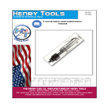
General Safety and Maintenance Manual
4 HORSEPOWER
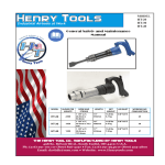
SUPER HEAVY DUTY VERTICAL GRINDERS
4 Horsepower Vertical Grinders
4 HORSEPOWER
Model
Number
Throttle
Type
Power
Output
65VL
LEVER
4 H.P.
(3000 W)
65VS
SAFETY
LEVER
Weight
Height over
Spindle
Air
Consumption
50 cfm
(23.6 L/s)
11.0 Lbs.
(5.0 Kg)
7.7 Inches
(196 cm)
Rated Speed/Wheel Capacity
4500 RPM w/ 9 Inch T27 Wheel Guard
4500 RPM w/ 9 Inch T28 Wheel Guard
6000 RPM w/ 7 Inch T27 Wheel Guard
6000 RPM w/ 7 Inch T28 Wheel Guard
6000 RPM w/ 9 Inch T27 Wheel Guard
6000 RPM w/ 9 Inch T28 Wheel Guard
8000 RPM w/ 7 Inch T27 Wheel Guard
8000 RPM w/ 7 Inch T28 Wheel Guard
(NOTE: Standard RPM is 6000RPM)
The Henry Tool Co., Manufactured by Henry Tools
498 So. Belvoir Blvd., South Euclid, OH 44121 U.S.A.
Ph: (216) 291-1011 or (800) 826-5257 ● Fax: (216) 291-5949 or (800) 303-2800
Email: [email protected] ● Website: www.Henrytools.com
General Operators Instructions and Service Manual
Description
Part Number
Description
200-9
O-Ring
AA-650-1-AL
500-46
Snap Ring
Handle Assembly (Complete)
(Non-lockout handle)
550-33-L
Live Handle Adaptor bushing
AA-650-1-ALS
550-33-SW
Screen Filter
Safety Lock Handle Assembly
(Complete)
550-33-SP
Spacer
650-33
Screen Bushing(1/2x3/8)
550-38
Lever
650-54
Safety Lock Pin
550-50
Lever Pin
650-55
Safety Lock Spring
560-13
Throttle Valve Assembly
650-56
Safety Lock Lever
650-57
Set Screw
700-30
O-Ring
700-48
Cap Screw
700-54
Lock Washer
700-S-26
Plug
700-S-26-GK
Gasket
841555
Screen Bushing (1/2X1/2)
with 200-9 O-ring installed
600-51
Plunger Spring
650-1-AL
Live Handle Body (Non-Lockout
type)
650-1-ALS
Safety Lock Valve Body(Bare)
www.HenryTools.com | Page 171
For additional product information visit our website.
Ph:
Part Number
HENRY TOOLS, INC. (216) 291-1011 or (800) 826-5257
MODELS
65 VL
65 VS
Revised 02/19/12
General Operators Instructions and Service Manual
www.HenryTools.com | Page 172
For additional product information visit our website.
Revised 02/19/12
Ph:
HENRY TOOLS, INC. (216) 291-1011 or (800) 826-5257
Note: The grinding wheel shown has a threaded hub.
MODELS
65 VL
65 VS
General Operators Instructions and Service Manual
650-1-BTG
655-8
650-13
560-13
650-33
650-54
600-51
650-55
650-56
650-57
650-58
650-59
650-1-AL
650-1-ALS
700-6
700-7
700-9
700-10
700-11
700-12
700-13
700-15
700-16
DESCRIPTION
O-RING
DEAD HANDLE
WHEEL FLANGE
WHEEL FLANGE
SNAP RING
BEARING COVER
ADAPTOR CAP
Lever
SCREW (4 REQ.)
PIN
LEVER PIN
WASHER (4 REQ.)
Case (Bare)with RPM tag installed
BEARING SUPPORT
(new style)
GASKET (3 holed)
SPINDLE
GASKET
VALVE with 200-9 O-Ring
3/8-1/2 BUSHING
LOCKOUT LEVER PIN
SPRING
SPRING
LOCKOUT LEVER
SET SCREW
SCREW
WASHER
NON-LOCKOUT LEVER HANDLE (BARE)
LOCKOUT LEVER HANDLE HANDLE
(BARE)
LOCK RING (OLD STYLE) still supported
by Henrytools
BEARING
BEARING
END PLATE
CYLINDER (with pins installed)
ROTOR
BLADE (4 are Req’d)
KEY
REAR END PLATE
www.HenryTools.com | Page 173
PART NO.
700-30
700-34
700-37
700-46
700-47A
700-48
700-49
700-54
700-S-26
700-S-26-GK
1000-5
841555
GUARDS
700-200
700-201
412988
WRENCHES
1100-094
1100-200
1102-015
102-SPWR
ASSEMBLIES
650-50
AA-660-1
AA-650-1-AL
AA-650-1-ALS
DESCRIPTION
O-RING
SPINDLE NUT
CYLINDER PIN
WASHER (4-8 REQ.)
SCREW (4 REQ.)
SCREW
SCREW (Old Style)
WASHER
CAP
GASKET
SNAP RING
1/2x1/2 BUSHING
7” TYPE 27 GUARD
9” TYPE 27 GUARD
6” CUP GUARD
15/16” WRENCH
2” WRENCH
WHEEL LOCK ALLEN WRENCH
SANDING PAD NUT WRENCH
WHEEL LOCK ASSY.
CASE ASSY.(Includes all screws) Specify
the speed
LEVER LIVE HANDLE ASSEMBLY COMPLETE with screwsNON lockout Style
LOCKOUT LEVER LIVE HANDLE ASSEMBLY COMPLETE with screws
GOVERNORS
AA-550-45
GOV. ASSY(4500RPM)
AA-550-60
GOV. ASSY (6000RPM)STANDARD
AA-550-72
GOV. ASSY(7200RPM)
AA-550-80
GOV. ASSY(8000RPM)
• OTHER SPEEDS AVAILABLE
ACCESSORIES
849259
SANDING PAD NUT
849913
7” SANDING PAD
(MAX 8500 RPM)
849914
9” SANDING PAD (MAX 6500RPM)
For additional product information visit our website.
Revised 02/19/12
Ph:
PART NO.
200-9
550-1-C
550-12A
550-12B
550-21
550-25
550-33 -L
550-38
550-48
550-49
550-50
550-54
650-1
650-1-BTB
HENRY TOOLS, INC. (216) 291-1011 or (800) 826-5257
MODELS
65 VL
65 VS
General Operators Instructions and Service Manual
REPAIR KIT
510124
DESCRIPTION
DEPRESSED CENTER WHL. ADAPTOR
KIT.
REPAIR KIT Includes the following:
(1) 700-7 Bearing
(1) 700-9 Bearing
(1) 1000-5 Snap Ring
(1) 650-13 Gasket
(1) 650-1-BTG Gasket
(4) 700-13 Blades
DISASSEMBLY
1. Disconnect air and remove all wheels and accessories from grinder.
2. Secure the dead handle (550-1-C) of the qrinder in a vise. Remove
the three socket head screws (700-47A) and remove wheel guard.
3. Grasp the wheel flange (550-12A) and pull the complete motor assembly from the case.
4. Put the flats of the wheel flange (550-12A) in the vise and remove
governor. (NOTE:LEFT HAND THREAD)
5. Remove lock ring (1000-5). Holding the cylinder (700-11) in the
left hand, place a long tap pin in the hole left by the removal of the
governor. With a small hammer, tap light]y on the end of this pin,
which seperates the spindle (650-8) from the rear bearing (700-9)
and the rear thrust (700-16).
6. Remove cylinder (700-11), rotor blades (700-13) and rotor (70012). Do not remove key (700-15) at this time.
7. Clamp a suitable spindle holder or Rotor (700-12) in vise vertically. Line up the keyway in the holder and slide the spindle assembly through. Remove wheel flange (right hand thread) with suitable
wrench.
8. Remove spindle assembly from vice. Remove key and press spindle
out of bearing support. (650-1-BTB). Support bearing (700-7) and
press spindle throuqh.
9. Remove (550-21) snap ring, spacer (550-25) and bearing (700-7).
(Optional Step): To check throttle valve, unscrew plug (700-S10.
26) and lift out valve spring (600-51) and plunger (560-13). Remove
the “o” ring (200-9) with a sharp tool and replace with a new ring.
REASSEMBLY
1. Seat (700-7) bearing in bearing support(650-1-BTB), place (55025 ) spacer rounded edges facing toward bearing and secure with
(550-21) snap ring.
www.HenryTools.com | Page 174
2. Press spindle into bearing support &
through the(700-7)bearing.
3. Place key (700-15) into spindle keyway.
4. Clamp a suitable spindle holder or use
Rotor (700-12)in vise vertically. Line up the
keyway in the holder and slide the assembly
through.
5. Thread wheel flange(550-12-A) onto
spindle Tighten down with suitable wrench.
Remove entire assembly from vise.
6. Clamp wheel flange (550-12B) in vise.
7. Line up cylinder pin holes in the bearing support (650-1-BTB) and the front thrust
(700-10).
8. Put key (700-15) in spindle keyway and
slide rotor (700-12)down arbor and insert
blades (700-13). Put cylinder (700-11) into
place(NOTE:
9. Numerous holes on top of cylinder face
upwards .
10. Slip rear bearing (700-9) in rear thrust
(700-16) and press onspindle.(Press on
inner race of bearing.) Be sure that short
dowel pin in cylinder goes into hole in rear
thrust(700-16).
11. Place lock ring (1000-5) on spindle.
(There is no groove.)
12. Prior to reassembly inspect governor for
any damage. (i.e. gouges,nicks or dents).
13. Screw governor (AA-550-XX) tightly onto
rear spindle. (NOTE:THIS IS LEFT HAND
THREAD) Oil governor and inside of motor.
14. Assemble live handle; install live and
dead handles to case (650-1);place gasket
(650-13) in rear face of case.
15. Place gasket (650-1-BTG) over holes in
the case of (650-1). Then drop motor assembly package in case and line up holes in front
bearing support with those in front of case.
16. Replace the guard by lining up guard
holes with the motor holes. Install the three
bolts (700-47A) and lockwashers (700-46).
Tighten bolts down until snug then back off
1/2 turn.
17. Connect tool to air supply and apply air in
several short bursts.
18. Now run tool and tighten down bolts
evenly. (Alternating from corner to corner).
19.CHECK RPM WITH A RELIABLE
TACHOMETER. TOOL MUST RUN AT OR
BELOW SPEED THAT IS STAMPED ON THE
TOOL.
For additional product information visit our website.
Revised 02/19/12
Ph:
PART NO.
849269
HENRY TOOLS, INC. (216) 291-1011 or (800) 826-5257
MODELS
65 VL
65 VS
General Operators Instructions and Service Manual
Wheels known to have been subjected to improper mounting procedures can
burst violently and should be destroyed rather than risk their use by someone
who may not notice that the wheels are damaged.
Type 11 Wheel Mounting
(CUP WHEELS)
Note: The grinding wheel shown above has threaded hub.
Note: the 650-60 is shipped STANDARD on your Vertical Grinder.
WARNING: FRAGMENTS FROM AN ABRASIVE
WHEEL THAT BREAKS OR COMES APART WHILE
ROTATiNG CAN CAUSE SERIOUS INJURY OR EVEN
DEATH. NEVER OPERATE A WHEEL TYPE GRINDER
WITHOUT A GUARD.
Cup wheels are mounted directly onto
the tool. No additional accessories are
required.
Ph:
Type 27, 28 or 29 Depressed center wheels can be mounted as shown below.
HENRY TOOLS, INC. (216) 291-1011 or (800) 826-5257
General Wheel Mounting Instructions
MODELS
65 VL
65 VS
Your new Vertical grinder flanges must be flat, not relieved, and free of nicks or burrs. Flanges for Type 6 or 11
wheels must be at least 1/3 the wheel diameter. Always use wheel retainer supplied by manufacturer on Type 6 or
I1 wheels(CupWheels). When using depressed center wheels, only use adapters supplied by the manufacturer unless
they are furnished as a part of the wheel. Do not reuse throwaway adapters attached to depressed center wheels by
the manufacturer. Spindles must not be bent and threads must be free of any damage that might keep a wheel from
being centrally mounted or seated properly against driving flange. Wheel must be sufficiently tightened to prevent
spin-off. Before using or after mounting wheel, the tool must be run for one minute in a protected enclosure to check
integrity of the wheel.
INSPECT THE WHEEL OR ACCESSORY
Check the maximum safe RPM marked on the wheel or accessory. Never use a wheel or accessory rated below the
actual tool speed. Cracked, dropped, faulty, or bent accessories are dangerous. Suspect accessories should not be
used and should be disposed of. Inspect wheel for cracks or chips, water stains, or signs of abuse or improper storage Cracked or faulty grinding wheels are dangerous. They must be destroyed rather than risk their use by someone
who may not notice that they are damaged.
www.HenryTools.com | Page 175
For additional product information visit our website.
Revised 02/19/12
General Operators Instructions and Service Manual
• This tool is not designed for working in explosive environments, including those caused by fumes and dust, or near
flammable materials.
• This tool is not insulated against electric shock.
• Be aware of buried, hidden or other hazards in your work
environment. Do not contact or damage cords, conduits, pipes
or hoses that may contain electrical wires, explosive gases or
harmful liquids.
• Keep hands, loose clothing, long hair and jewelry away from
working end of tool.
• Power tools can vibrate in use. Vibration, repetitive motions
or uncomfortable positions may be harmful to your hands and
arms. Stop using any tool if discomfort, tingling feeling or pain
occurs. Seek medical advice before resuming use.
• Keep body stance balanced and firm. Do not overreach when
operating this tool. Anticipate and be alert
for sudden changes in motion, reaction torques, or forces during start up and operation.
• Tool and/or accessories may briefly continue their motion
after throttle is released.
• To avoid accidental starting - ensure tool is in “off” position
before applying air pressure, avoid throttle
when carrying, and release throttle with loss of air.
• Ensure work pieces are secure. Use clamps or vises to hold
work piece whenever possible.
• Do not carry or drag the tool by the hose.
• Do not use power tools when tired, or under the influence of
medication, drugs, or alcohol.
• Never use a damaged or malfunctioning tool or accessory.
• Do not modify the tool, safety devices, or accessories.
• Do not use this tool for purposes other than those recommended.
• Use accessories recommended by Ingersoll-Rand.
• Do not use this tool if the actual free speed exceeds the
rated rpm. Check the free speed of the Grinder before mounting a wheel, after all tool repairs, before each job and after
every 8 hours of use. Check
speed with a calibrated tachometer, without the abrasive
product installed.
• Do not use any wheel or other abrasive accessory whose
maximum operating speed, as defined by its manufacturer, is
less than the rated speed of the Grinder.
• Inspect all grinding wheels for chips or cracks prior to
mounting. Do not use a wheel that is chipped,
cracked or otherwise damaged.
• Inspect arbor, threads & clamping devices for damage &
wear prior to mounting wheel or other abrasive accessory.
• Do not use a grinding wheel that has been exposed to freezing temperatures, extreme temperature
changes, high humidity, solvents, water or other liquids.
• Make certain grinding wheel or other abrasive accessory
properly fits the spindle. The wheel should not fit too snugly or
too loosely. Plain hole wheels should have about .007” (0.17
mm) maximum diametral
clearance. Do not use reducing bushings to adapt a wheel to
any arbor unless such bushings are supplied by and recommended by the wheel manufacturer.
• Blotters shall always be used between flanges and abrasive
wheel surfaces to ensure uniform distribution of flange pressure (except type 27 & 28 wheels) and shall cover the entire
contact area of the wheel flange.
• Always use the wheel flanges furnished by the manufacturer
www.HenryTools.com | Page 176
and appropriate for the wheel size and type.
Never use a makeshift flange or plain washer. Flanges should be in good
condition and free of nicks, burrs and sharp edges.
• Ensure that the thread type and size of the threaded abrasive product
exactly matches the thread type and size of the spindle.
• Prevent the spindle end from touching the bottom of the hole of cups,
cones or plugs with threaded holes, intended to be mounted on machine
spindles, by comparing dimensions and other relevant data for them.
• Ensure that the grinding wheel or other abrasive accessory is correctly
mounted and tightened before use.
• Before starting this tool, the operator shall make sure that no one is in
the plane of rotation.
• Wear Personal Protective Equipment and remove flammable objects
from the work area to ensure that sparks and debris do not create a
hazard when using this tool.
• After mounting a wheel or other abrasive accessory, the Grinder shall
be run in a protected enclosure, at gradually increasing speed, for at
least 60 seconds. Make certain no one is in front of or in line with the
wheel or other abrasive accessory. Be aware that it may fail at this time
if it is defective, improperly mounted or the wrong size and speed. Stop
immediately if considerable vibration or other defects are detected. Shut
off the air supply and determine the cause.
• Do not use this tool on materials whose dust or fumes can cause a
potentially explosive environment.
• When starting a cold wheel, apply it to the work slowly until the wheel
gradually warms up. Make smooth contact with the work, and avoid any
bumping action or excessive pressure.
• If the grinder is dropped or bumped, turn off the air supply and carefully examine the grinding wheel or other abrasive accessory. Discard it if
damaged, chipped or cracked. Before reuse, run the grinder in a protected enclosure following the same precautions used after first mounting.
• Before a grinder is put down, the throttle shall be released and the
wheel or other accessory shall come to a stop. Tool rests, hangers, and
balancers are recommended.
Additional Warnings for Guarded Grinders
• Do not use this Grinder without the furnished Wheel Guard.
• Incorrect combinations of grinder wheel, wheel guard and tool speed
could result in injury. Ensure that combinations are correct per the Product Specifications.
• Always replace a damaged, bent or severely worn wheel guard. Do not
use a wheel guard that has been subjected to wheel failure.
• Guard opening must face away from the operator. Bottom of wheel
must not project beyond guard.
Additional Warnings for Unguarded Grinders
• Do not use an unguarded grinder unless used for internal work and only
operated when the work offers protection.dditional Warnings for Use of
Cut-off Wheels (Type 1 and 27A)
• When cutting, support the workpiece so the slot is kept at constant or
increasing width during the whole operation.
• If the abrasive product gets jammed in a cut slot, shut off the grinder
and ease the wheel free. Check that the wheel is still correctly secured
and not damaged before continuing the operation.
• A cut-off wheel shall NOT be used for side grinding.
For additional product information visit our website.
Revised 02/19/12
Ph:
Product Safety information - When
Using the Tool:(continued)
HENRY TOOLS, INC. (216) 291-1011 or (800) 826-5257
MODELS
65 VL
65 VS
General Operators Instructions and Service Manual
HENRY TOOLS, INC. (216) 291-1011 or (800) 826-5257
MODELS
65 VL
65 VS
Product Safety information - When Using the
Tool:(continued)
The 6 & 11 cup wheels remove large amounts of metal and are good
for open spaces. Use a Type 27 & 28 wheel for weld grinding, notch and
gate removal, pipe beveling and repair or in metal fabrication, petrochemical maintenance or construction.
Ph:
Your selection and purchase of finishing tools has a direct effect on
process and product quality. Your decision can make a difference in finishing efficiency and in the improved quality and durability of finishes.
Only use recommended equipment and adaptors. Inspect grinding
wheels closely for any imperfections, damage or broken edges. Use
correct size guards, flanges, blotters, spindles and mounting practices
to ensure operator safety. All give you the ability to match capacity
and attachment precisely to the work piece and material for finessing a
high quality finish.
After mounting a wheel or other abrasive accessory, the Grinder shall
be run in a protected enclosure or under a work bench, at a gradually
increasing speed, for at least 60 seconds. Make certain no one is in
front of or in line with the wheel or other abrasive accessory. Be aware
that it may fail at this time if it is defective, improperly mounted or the
wrong size and speed. Stop immediately if considerable vibration or
other defects are detected. Shut off the air supply and determine the
cause.
www.HenryTools.com | Page 177
For additional product information visit our website.
Revised 02/19/12
General Operators Instructions and Service Manual
ALWAYS COMPLY WITH:
1.General Industry Safety & Health Regulations, Part 1910,
OSHA 2206, available from: Sup’t of Documents; Government
Printing Office; Washington DC 20402
2.Safety Code for Portable Air Tools, ANSI B186.1 available from:
American National Standards Institute, Inc.; 1430 Broadway; New
York, NY 10018
3.State and Local regulations.
Portions of the above codes and regulations are listed below for
quick reference.
THESE EXCERPTS ARE NOT INTENDED TO BE ALL INCLUSIVE - STUDY
AND COMPLY WITH ALL REGULATIONS!
Do Not Throw Away
These Instructions!!
IMPORTANT SAFETY INFORMATION ENCLOSED.
READ AND UNDERSTAND THIS MANUAL BEFORE OPERATING TOOL.
IT IS THE RESPONSIBILITY OF THE EMPLOYER TO PLACE THE
INFORMATION IN THIS MANUAL INTO THE HANDS OF THE OPERATOR.FAILURE TO OBSERVE THE FOLLOWING WARNINGS COULD
RESULT IN INJURY.
PLACING TOOL IN SERVICE
• Always operate, inspect and maintain this tool in accordance with all
regulations (local, state, federal and country), that may apply to hand
held/hand operated pneumatic tools.
• Always turn off the air supply and disconnect the air supply hose
before installing, removing or adjusting any accessory on this tool, or
before performing any maintenance on this tool.
• Do not use damaged, frayed or deteriorated air hoses and fittings.
• Be sure all hoses and fittings are the correct size and are tightly secured. l Always use clean, dry air at 90 psig (6.2 bar/620 kPa) maximum
air pressure. Dust, corrosive fumes and/or excessive moisture can ruin
the motor of an air tool.
• Do not lubricate tools with flammable or volatile liquids such as kerosene, diesel or jet fuel.
Do not remove any labels. Replace any damaged label.
1.TOOL INTENT -Henry Tools vertical Grinders are designed for heavy
material removal. For consistent, quality performance in foundries, welding
shops, fabrication facilities, steel mills and shipyards. Tools shall be used
only for purposes intended in their design (refer to product catalog).
2.AIR SUPPLY - Test and operate tools at 90 PSIG (6.2 bar/620 kPa)
maximum air pressure at the inlet with 3/8” (10 mm) inside diameter
air supply hose. Use recommended airline filters-regulators-lubricators.
Choose tools with enough horsepower to drive the abrasive material you
are using, and allow the grinder’s speed to work for you.
3.UNUSUAL SOUND or VIBRATION - If tool vibrates or produces an
unusual sound, repair immediately for correction.
4.OPERATOR PROTECTIVE EQUIPMENT - Wear goggles or face shield
www.HenryTools.com | Page 178
at all times tool is in operation. Other protective clothing shall be worn, if necessary. SEE
REGULATIONS.
5.SAFETY MAINTENANCE PROGRAM - Employ a safety program to provide inspection and
maintenance of all phases of tool operation and
air supply equipment in accordance with “Safety
Code for Portable Air Tools.”
WARNING: The signal word ‘Warning” identifies all notes on safe work practices in this
operating instruction, alerting to hazards for
life and health of people. Observe these notes
and proceed with special care in the cases described. Pass all safety instructions on to other
operators. In addition to the safety instructions
in this operating instruction, the general local
safety and accident prevention rules must be
observed.
Important Notes
CAUTION The signal word “caution!” identifies
all portions of this operating instruction meriting special attention to ensure that guidelines,
rules, hints and the correct work procedures
are observed; and, to prevent damage to and
destruction of the grinder and/or parts.
A recommended spare part (or set) for every
five (5) tools. Small, low cost or easily lost parts
should be stocked as 3-4 per 10 tools.
WARNING’: Disconnect the air supply hose
before servicing the tool.
INSTALLATION
For most efficient operation, 90 psig (620 kPa)
of clean dry air is required at the tool with the
tool running, with-out extreme fluctuation.
Minimum recommended hose size is 3/8” I.D.
when the length of the hose is eight feet or less.
An air line filter and lubricator, should be used.
Hose should be blown out before attaching to
the tool.
Loss of Power
A loss of power may not be related to the tool.
First, check the air line pressure. It should be
90 psi at the tool while operating.
LUBRICATION
Lubricate the motor with an air line lubricator,
using a light air motor oil. Adjust the lubricator
to dispense one drop per cycle or three drops
per minute.
CAUTION Do not use substitutes for oil and
grease. This could
result in damage to the tool.
MAINTENANCE
1. Proper and continuous lubrication.
2. Blow out air hose to assure a clean air supply.
3. Be sure the air filter and line lubricator are
clean.
For additional product information visit our website.
Revised 02/19/12
Ph:
SAFETY FIRST!
HENRY TOOLS, INC. (216) 291-1011 or (800) 826-5257
MODELS
65 VL
65 VS
General Operators Instructions and Service Manual
4. Fill the line lubricator before operation.
5. Place a few drops of oil into the air inlet of the tool
be-fore attaching the air line.
6. Use moisture separators to remove water from the
air line.
7. CAUTION Do not use solvent on bearings or on any
parts made of a synthetic material.
8. Do not remove bearings unless replacement is
necessary; bearings are a press fit.
Always wear eye protection when operating or performing maintenance on this tool.
Always wear hearing protection when operating this
tool.
Keep hands, loose clothing and long hair away from
rotating end of tool.
Anticipate and be alert for sudden changes in motion
during start up and operation of any power tool.
Keep body stance balanced and firm. Do not overreach when operating this tool. High reaction torques
can occur at or below the recommended air pressure.
Tool accessories may continue to rotate briefly after
throttle is released.
Air powered tools can vibrate in use. Vibration, repetitive motions or uncomfortable positions may be
harmful to your hands and arms. Stop using any tool
if discomfort, tingling feeling or pain occurs.
Seek medical advice before resuming use.
Use accessories recommended by Henry Tools.
This tool is not designed for working in explosive
atmospheres.
This tool is not insulated against electric shock.
Product Description
An Air Grinder is a compressed air powered hand-held
rotary power tool driving a rotating arbor (spindle) on
which a grinding wheel or other abrasive accessory is
mounted. A guard is required on all grinders, unless
used with specific abrasive products and under special
conditions. See additional warnings given below for
Unguarded Grinders.
WARNING
General Product Safety Information
• It is your responsibility to make this safety
information available to others that will
operate this product.
• Failure to observe the following warnings could
result in injury.
WARNING
Product Safety information - When Placing the Tool in
Service
• Always install, operate, inspect and maintain this
product in accordance with all applicable standards
and regulations (local, state, country, federal, etc.).
• Always use clean, dry air at 90 psig (6.2 bar/620
kPa) maximum air pressure at the inlet. Higher pressure
may result in hazardous situations including excessive
www.HenryTools.com | Page 179
speed, rupture, or incorrect output torque or force.
• Be sure all hoses and fittings are the correct size and are tightly
secured.
• Install a properly sized Safety Air Fuse upstream of hose and use an
anti-whip device across any hose coupling without internal shut-off, to
prevent hose whipping if a hose fails or coupling disconnects.
• Ensure an accessible emergency shut off valve has been installed in
the air supply line, and make others aware of its location.
• Do not use damaged, frayed or deteriorated air hoses and fittings.
• Keep clear of whipping air hoses. Shut off the compressed air before
approaching a whipping hose.
• Always turn off the air supply, bleed the air pressure and disconnect
the air supply hose before installing, removing or adjusting any accessory on this tool, or before performing any maintenance on this tool or
any accessory.
• Do not lubricate tools with flammable or volatile liquids such as
kerosene, diesel or jet fuel. Use only recommended lubricants.
• Use only proper cleaning solvents to clean parts. Use only cleaning
solvents which meet current safety and health standards. Use cleaning
solvents in a well ventilated area.
• Keep work area clean, uncluttered, ventilated and illuminated.
• Do not remove any labels. Replace any damaged label.
• For those grinders designed for use with wheels of four inches
diameter and larger, separate the grinder from any quick-disconnect
couplings by a hose whip. Never install a quick-disconnect directly into
these tools.
WARNING
Product Safety information - When Using the Tool:
• Always wear eye protection when operating or performing maintenance on this tool.
• Always wear hearing protection when operating this tool.
• Always use Personal Protective Equipment appropriate to the tool
used and material worked. This may include dust mask or other
breathing apparatus, safety glasses, ear plugs, gloves, apron, safety
shoes, hard hat and other equipment.
When wearing gloves always be sure that the gloves will not prevent
the throttle mechanism from being released.
• Prevent exposure and breathing of harmful dust and particles created by power tool use.
- Some dust created by power sanding, sawing, grinding, drilling, and
other construction activities contains chemicals known to cause cancer, birth defects or other reproductive harm. Some examplesof these
chemicals are:
- lead from lead based paints,
- crystalline silica from bricks and cement and other masonry products, and arsenic and chromium from chemically treated lumber.
- Your risk from these exposures varies, depending on how often you
do this type of work. To reduce your exposure to these chemicals:
work in a well ventilated area, and work with approved safety equipment, such as those dust masks that are specially designed to filter
out microscopic particles.
• Keep others a safe distance from your work area, or ensure they use
appropriate Personal Protective Equipment.
For additional product information visit our website.
Revised 02/19/12
Ph:
Safety continued.......
HENRY TOOLS, INC. (216) 291-1011 or (800) 826-5257
MODELS
65 VL
65 VS