1
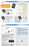
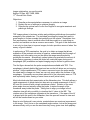
Image optimization: you are the artist
Kathryn E Glas, MD, FASE, MBA
17th Annual Echo Week
Objectives:
1. Describe probe manipulations necessary to optimize an image
2. Explain the use of settings to optimize imaging
3. Describe the optimal use of color-flow Doppler to recognize anatomic and
pathologic findings
TEE images shown in lectures, articles and guidelines publications show perfect
examples of the stated view. The individual providing the image likely went to
great lengths to find an example that perfectly met the criteria. Remember from
first year anatomy class in medical school that there really is no such thing as
normal, and variants can be as common as normals. The goal of this discussion
is not only to show how to improve images, but also provide a sense of when ‘the
enemy of good is better’.
In performing a TEE examination, the goal is to obtain an image that allows
evaluation of the anatomic structure in question, understanding that the angle of
obtaining such information may not be within the range recommended by
guidelines documents. Alternatively, patient status may preclude the amount of
probe flexion necessary to show the entire left ventricular apex during a mid
esophageal (ME) evaluation and apical imaging may be limited to gastric views.
The first figure shown lists the probe manipulations available with TEE. The
esophagus is directly behind the heart and we use the left atrium as our imaging
window. Unlike transthoracic (TTE) exams, we cannot move the probe across
the chest wall to change our views- we can only move within the confines of the
esophagus. Fortunately we can obtain almost all of the information seen on TTE
and importantly better viewing of some items as well (mitral valve).
Most individuals start their examination at the 4chamber view. This both allows a
rapid assessment of global status but also sets up a rapid assessment of the LV,
MV and AV structures with a single omniplane rotation. Rotation of the omni
plane angle does not actually rotate the probe, it rotates the angle of the
transducer array inside the probe. Taking time to align your image in the 4
chamber view will aid your ability to visualize the LV views in the ME. The
rotation axis of the omniplane originates at the transducer. If the apex of the LV
is aligned with this point in the 4chamber, then the apex will remain in view and
will not be foreshortened as you rotate.
Keep in mind that small, even minute, manipulations can create an improvement
in the image. Don’t focus on the ominplane angle number, look at the image and
advance slowly until you see the structures key to any given view- both papillary
musles in the midcommissural or a single papillary muscle and the left atrial
appendage in the 2chamber. Slight ante- or retroflexion of the probe can
improve contact with the heart or add the small angulation difference necessary
to see both the MV and the LV apex in the ME views.
Flexing to the left or right is helpful when the heart position has been altered in
relation to the esophagus- an enlarged ascending aorta or descending aorta, for
example. There are two caveats here: first, large aneurysms can, in theory,
rupture with excessive force applied by a probe and second, moving the probe in
the locked position increases the risk of esophageal injury. It is strongly
recommended that the probe not be locked when manipulations are performed
on anesthetized patients.
Figure 2 shows the conventions of image display associated with TEE.
Dextrocardia cannot be diagnosed without adherence to the conventions. In LAX,
the aorta and IVC at 90 degrees follow this relationship, with the head of the
patient to the right of the display and the foot of the paitent to the left.
There are numerous pre and post processing manipulations that can be effective
in improving image quality. Adjustments to gain, compress, TGC, depth of
image, width of image, zoom function, grey scale, probe mHz, addition of
harmonics, Nyquist limit of color doppler, baseline and scale of spectral doppler
displays.
Some machines now have a single button that auto adjusts gain and compress.
While this is frequently adequate, additional adjustments are sometimes
indicated. Consult the user manual specific to your equipment will provide
helpful information on machine controls and image optimization techniques.
Gain- Controls the total gain of the active mode, be it gray scale in 2D or total
gain of spectral doppler modes
TGC-time gain compensation adjusts for depth-related attenuation of the image,
with each knob adjusting a different depth. The uppermost knob adjusts the
image at the top of the image.
Depth- controls the displayed depth of image display. Most TEE imaging can be
accomplished between 8 and 15 cm depth. 8-10 cm is optimal for mitral valve
imaging and 15 cm +/- for ME views including the LV, with greater depth needed
for larger hearts.
Zoom- allows selection of a small segment of the image to be magnified and
limits the image display to that small portion of interest.
Refe
erence:
Hahn
n RT, Abrah
ham T, Ada
ams MS, Brruce CJ, Gllas KE, Lan
ng RM, Ree
eves ST,
Shan
newise JS, Siu SC, Ste
ewart W, Picard
P
MH; A
American S
Society of
Echo
ocardiograp
phy; Society
y of Cardiov
vascular An
nesthesiolo
ogists. Guid
delines for
perfo
orming a co
omprehensive transeso
ophageal e
echocardiog
graphic exa
amination:
recom
mmendatio
ons from the
e American Society off Echocardio
ography an
nd the
Socie
ety of Cardiovascular Anesthesio
ologists. An
nesth Analg
g. 2014 Jan; 118(1):2168.
http:///pie.med.u
utoronto.ca//TEE/TEE_
_content/TE
EE_probeMa
anipulation_intro.html