1
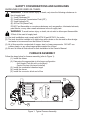
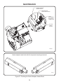
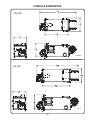
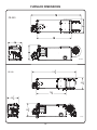
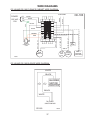
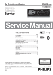
OWNER’S MANUAL
CE-140 Mul-Oil Furnace
CE-180 Mul-Oil Furnace
CE-250 Mul-Oil Furnace
With CE-3 Burner
CE-330 Mul-Oil Furnace
With CE-4 Burner
Clean Energy Heating Systems, LLC
540 Maple Street, Honey Brook, PA 19344
www.CleanEnergyHeatingSystems.com
(888) 519-2347
WARNING: For your safety - DO NOT store gasoline or other flammable
vapors and liquids in the vicinity of this or any appliance.
8/22/12
Part # 70001
TABLE OF CONTENTS
SAFETY CONSIDERATIONS AND GUIDELINES..............................................................4
FURNACE ASSEMBLY....................................................................................................... 6
(1) Installing the blower........................................................................................... 7
(2) Air discharge configuration................................................................................ 9
- Unit Heater (Free Air with no ductwork)
- Central Furnace (ductwork installed)
(3) Installing the combustion chamber target.......................................................... 12
(4) Installing the burner........................................................................................... 13
(5) Installing the connector block and oil line.......................................................... 14
FURNACE INSTALLATION........................................................................... ..................... 15
(1) Selecting a location........................................................................................... 16
(2) Mounting the furnace in position........................................................................ 17
(3) Connecting the electrical supply........................................................................ 18
(4) Installing the chimney components................................................................... 19
(5) Oil storage tank set up ...................................................................................... 21
(6) Installing the metering pump and oil lines......................................................... 21
(7) Connecting the compressed air line.................................................................. 26
(8) Installing the wall thermostat............................................................................. 27
PREPARING THE METERING PUMP FOR START UP..................................................... 27
STARTING AND ADJUSTING THE BURNER.................................................................... 28
(1) Preparing the burner for start up....................................................................... 28
(2) Priming the oil pump.......................................................................................... 28
(3) Adjusting the Burner.......................................................................................... 28
RESETTING THE OIL PRIMARY CONTROL.....................................................................29
SETTING THE DRAFT........................................................................................................30
MAINTENANCE.................................................................................................................. 31
FURNACE DIMENSIONS................................................................................................... 35
WIRE DIAGRAMS.............................................................................................................. 37
PARTS DIAGRAMS............................................................................................................ 42
SERVICE RECORDS......................................................................................................... 66
WARRANTY INFORMATION............................................................................................. 67
SAFETY CONSIDERATIONS AND GUIDELINES
HAZARD DEFINITIONS:
NOTICE: Intended to clarify or bring special attention to previous information.
CAUTION: Indicates a hazardous situation, which can result in minor or moderate
personal injury if not avoided.
WARNING: Indicates a hazardous situation, which can result in death or serious
personal injury if not avoided.
DANGER: Indicates a hazardous situation, which will result in death or serious
personal injury if not avoided.
SAFETY CONSIDERATIONS:
WARNING: Incorrect installation, adjustment, or misuse of this heating equipment
could result in death, severe personal injury, or substantial property damage.
To the Equipment Owner:
• Read and understand all instructions
provided in this manual
• Installation and service must be
completed by qualified personnel who
are familiar with oil-fired appliances.
• Save this manual for future reference.
To the Professional, Qualified Installer or
Service Agency:
• Read and carefully follow all instructions
provided in this manual before installing, starting,
or servicing this heating equipment.
• All installations must be made in accordance
with state and local codes having jurisdiction.
DANGER: DO NOT store or use gasoline or other flammable/explosive liquids/vapors
in or around the furnace.
DANGER: DO NOT operate the furnace if excess oil, oil vapors, or fumes have
accumulated in or around the furnace.
DANGER: Improper installation, operation, or maintenance of the furnace may create
a fire or explosion hazard.
WARNING: DO NOT mix unapproved substances to the used oil supply, such as:
• Anti-Freeze
• Carburetor Cleaner
• Paint Thinner
• Parts Washer and/or Solvents
• Gasoline
• Oil Additives
• Chlorinated solvents
• Any other inappropriate / hazardous material
Instruct your personnel NEVER to add unapproved substances to your used oil.
Burning any unapproved substance will immediately void the furnace warranty and
may cause damage and unsafe operating conditions.
WARNING: Unauthorized furnace modifications may cause damage and unsafe
operating conditions.
4
SAFETY CONSIDERATIONS AND GUIDELINES
WARNING: The CE-3 Burner is only approved for use on a furnace manufactured by
Clean Energy Heating Systems. The Furnace is only approved for use with the CE-3
burner manufactured by Clean Energy Heating Systems.
WARNING: The installation, operation, and maintenance of this equipment in the
United States must be done by qualified personnel according to instructions in the
Clean Energy Heating Systems Owner’s Manual and in accordance with all national,
state, and local codes or authorities having jurisdiction and the following standards:
NFPA 30
Flammable and Combustible Liquids Code
NFPA 30A Automotive and Marine Service Station Code
NFPA 31
Installation of Oil Burning Equipment
NFPA 70
National Electrical Code
NFPA 88A Parking Structures
NFPA 88B Repair Garages
NFPA 211
Chimney’s, Fireplaces, Vents and Solid Fuel Burning Appliances
Likewise, the installation, operation, and maintenance of this equipment in Canada must
be done by qualified personnel according to instructions in the Clean Energy Heating
Systems Owner’s Manual and in accordance with all regulations and authorities having
jurisdiction and the following CSA Standards:
B139 Oil Burning Equipment
B140 General Requirements for Oil Burning Equipment
C22.1 Canadian Electrical Code, Part 1
GUIDELINES FOR FURNACE USE:
• This furnace is for industrial and/or commercial use only. This furnace is not intended
for residential use.
• This furnace is safety listed to burn the following fuels:
• #2 fuel oil
• Used crankcase oil up to 50 SAE
• Used hydraulic oil
• Used automatic transmission fluid (U.S.)
• The EPA regulations for burning used oil are as follows:
• Your supply of used oil is generated on-site. You may also collect oil from
“do-it-yourself” oil changers.
• Do not mix hazardous wastes, such as chlorinated solvents, with your used oil.
• The exhaust gases of the furnace must be vented to the outside with an
appropriate stack system.
• The furnace is used to recycle used oil for “heat recovery”. The furnace is not
to be used in warm weather just to dispose of used oil.
• Only trained authorized personnel should service and maintain the furnace. Be sure
the furnace receives annual maintenance to ensure safe and efficient operation.
5
SAFETY CONSIDERATIONS AND GUIDELINES
GUIDELINES FOR USED OIL TANKS:
WARNING: To avoid serious injury or death, only store the following substances in
the oil supply tank:
(1) Used Crankcase Oil
(2) Used Automatic Transmission Fluid (ATF)
(3) Used Hydraulic Oil
(4) #2 Fuel Oil (Diesel Fuel)
DO NOT put flammable or corrosive substances such as gasoline, chlorinated solvents,
paint thinner, or any other unsafe substance in the oil supply tank.
WARNING: To avoid serious injury or death, do not weld or allow open flames within
35 feet of the used oil supply tank.
(1) The tank installation must comply with NFPA 30 and NFPA 31 fire codes.
(2) The tank should be installed on a slight slope with a drain on the low end to allow sludge
and water to be removed from the bottom of the tank.
(3) All oil lines must be constructed of copper, steel, or brass components. DO NOT use
rubber, plastic, or any other inappropriate material for oil lines.
(4) Be sure to follow all instructions for tank installation in the Owner’s Manual.
FURNACE ASSEMBLY
Follow the steps below for furnace assembly (refer to Figure 1):
(1) Install the blower
(2) Determine the appropriate air discharge configuration
- Unit Heater (Free Air with no ductwork)
- Central Furnace (ductwork installed)
(3) Install the combustion chamber target
(4) Install the burner
(5) Install the connector block and oil line
1
3
2
CE70012
4
5
Figure 1: Typical Furnace Assembly
6
FURNACE ASSEMBLY
Installing the Blower (CE-140, CE-180, and CE-250):
(1) Refer to Figure 2.
(2) Place the blower inside the mounting angles on the back of the furnace with the blower
bubble turned up.
(3) Use the included #10 self-drilling screws to secure the blower housing to the mounting
angle brackets on the back of the furnace cabinet.
(4) Connect the flexible conduit from the blower motor to the rear electrical box.
(5) Connect the wire leads according to the electrical schematic label in the rear junction box.
(6) Fasten the blower guards with the remaining #10 self-drilling screws to each side of the
blower.
WARNING: Blower guards must be in place to prevent personal injury. NEVER
operate the furnace without all guards in place!
NOTICE: The blower motor is designed to operate with the guards in place. Without the
guards in place the blower will move more air which may overload and damage the blower
motor.
NOTICE: The blower must be mounted with the “bubble” turned up. If the blower is not
mounted in this position, the internal air flow through the furnace cabinet will change which
may cause the unit to cycle on high limit.
CE70019
Figure 2: Blower Assembly Installation (CE-140, CE-180, and CE-250)
Installing the Blower (CE-330):
(1) Refer to Figure 2A.
(2) Place the blower inside the mounting angles on the back of the furnace with the blower
bubble turned up.
(3) Use the included #10 self-drilling screws to secure the blower housing to the mounting
angle brackets on the back of the furnace cabinet.
(4) Fasten the motor bracket and tensioning bracket to the blower according to dimensions
shown in Figure 2A.
(5) Secure the motor to the motor bracket with the supplied hardware.
7
FURNACE ASSEMBLY
(6) Install the blower pulley and motor pulley. Use a straight edge to make sure the pulleys
are installed on the same plane.
(7) Install the belt on the pulleys and tighten the tensioning bracket to maintain proper belt
tension.
(8) Connect the flexible conduit from the blower motor to the rear electrical box and connect
the wire leads according to the electrical schematic label in the rear junction box.
(9) Fasten the blower guards with the remaining #10 self-drilling screws to each side of the
blower.
WARNING: Blower guards must be in place to prevent personal injury. NEVER
operate the furnace without all guards in place!
NOTICE: The blower motor is designed to operate with the guards in place. Without the
guards in place the blower will move more air which may overload and damage the blower
motor.
NOTICE: The blower must be mounted with the “bubble” turned up. If the blower is not
mounted in this position, the internal air flow through the furnace cabinet will change which
may cause the unit to cycle on high limit.
18.0"
4.5"
8.5
CE70059
Figure 2A: Blower Assembly Installation (CE-330)
8
FURNACE ASSEMBLY
Air Discharge Configurations:
Your Clean Energy Heating System may be installed in one of two ways:
1.
Unit Heater - Louvers are installed over the air outlet opening(s) to direct the hot air
flow in the desired direction.
2.
Central Furnace (Static Pressure) - Duct work applications with less than 0.30” W.C.
(inches of water column). Louvers are NOT installed. Ductwork is installed over the side
air outlet opening(s) to direct the hot air flow.
NOTICE: A qualified electrician should check the amp draw of the blower motor. Do not
operate the blower motor over 85% of the amp rating on the motor nameplate.
1.
Unit Heater Configuration
There are several options for mounting the louvers on a unit heater for free air applications.
Refer to Figures 3, 4, and 5. Cover the unused air outlet openings with the blank covers
provided (one is painted and one is galvanized). The blank covers can be split in two.
NOTICE: When splitting a side opening horizontally, the louvers should be positioned in the
top half of the air outlet opening. When splitting a side opening vertically, the louvers should
be positioned in the front (closest to the burner) half of the air outlet opening.
CE70040
Figure 3: Installing the Louvers
One Side Air Outlet Fully Open
9
FURNACE ASSEMBLY
CE70041
Figure 4: Installing the Louvers
Splitting the Air Outlet Openings Between Both Sides
CE70042
Figure 5: Installing the Louvers
Splitting the Air Outlet Openings Between one Side and Bottom
10
FURNACE ASSEMBLY
2.
Central Furnace (Static Pressure - Less than 0.30” W.C.)
DO NOT install the louvers. Install the ductwork directly over the desired SIDE air outlet
opening(s).
NOTICE: DO NOT install ductwork over the bottom air outlet opening. Proper air flow will not
be maintained and furnace damage may occur.
NOTICE: A qualified HVAC engineer should design the ductwork for your application and
determine the static pressure of the ductwork installed. Existing ductwork may not be suitable
for this furnace. Only connect ductwork to the side air outlets on the furnace. DO NOT
install ductwork on the bottom air outlet of the furnace. Refer to the tables below for air flow
specifications.
CE-140
Louvers Mounted on Furnace
No Louvers Installed
Ductwork Installed
on Furnace
No Ductwork
0.30” W.C.
1700 CFM
1400 CFM
Louvers Mounted on Furnace
No Louvers Installed
Ductwork Installed
on Furnace
No Ductwork
0.30” W.C.
1700 CFM
1400 CFM
Louvers Mounted on Furnace
No Louvers Installed
Ductwork Installed
on Furnace
No Ductwork
0.30” W.C.
2700 CFM
2400 CFM
Louvers Mounted on Furnace
No Louvers Installed
Ductwork Installed
on Furnace
No Ductwork
0.30” W.C.
3700 CFM
3300 CFM
CE-180
CE-250
CE-330
11
FURNACE ASSEMBLY
Installing the Combustion Chamber Target:
NOTICE: Damage to the combustion chamber may occur if the furnace is used with a
damaged or missing target. Inspect the target regularly for proper positioning and wear.
(1) Refer to Figure 6 to view the proper position of the combustion chamber target.
(2) Open the front door of the furnace by loosening the two over-center latches and swinging
the door open.
(3) Guide the target toward the back of the combustion chamber. Hang the loop on the back
of the target on the hook welded to the back of the combustion chamber.
(4) Close the front door and secure the two over center-latches.
Target hanging on back of
combustion chamber hook and
resting against stabilizer
CE70020
Target Stabilizer
Figure 6: Proper Position of the Combustion Chamber Target
12
FURNACE ASSEMBLY
Installing the Burner:
NOTICE: The nozzle, electrode, and retention head may need adjustment after shipping and
installation. The nozzle should remain centered in the retention head. Refer to Figure 7 for
proper dimensions.
(1) Remove the two serrated flange nuts from the front door.
(2) Slide the blast tube of the burner through the throat of the front door.
(3) Fasten the burner to the front door by tightening the two serrated flange nuts.
1/8" GAP BETWEEN
ELECTRODES
3/16" GAP
BETWEEN
ELECTRODES
AND NOZZLE
CE70018
ELECTRODE 1/8"
PAST NOZZLE
Figure 7: Nozzle and Electrode Settings
13
FURNACE ASSEMBLY
WARNING: To prevent the risk of electrical
shock, shut OFF main power to the furnace before
connecting or disconnecting the burner power
cord.
(4) Refer to Figure 8
(5) Line up the key in the receptacle with the slot in the
cord.
(6) Tighten the electrical cord when in position.
NOTICE: Make sure the plug and receptacle are
properly aligned. The ground prong in the receptacle
is longer than the other prongs and must be lined up
properly.
Installing the Connector Block and Oil Line:
(1) Refer to Figure 9 to position the connector block.
(2) Fasten the connector block to the side of the furnace
with the bolts provided.
(3) Install the supplied 3/8” copper tubing from the swivel
fitting in the connector block to the burner.
NOTICE: The connector block with the swivel fitting
must be used to allow the front door to swing open
properly. If the connector block is not used the oil line will
need to be disconnected before the door is opened.
CE70013
Figure 8: Installing the Burner Cord
CE70021
Oil Line Connector Block
Figure 9: Installing the Connector Block and Oil Line
14
FURNACE INSTALLATION
Refer to Figure 10 for a typical furnace installation illustration.
3 FT.
(MIN.)
Installation of your furnace will include the following steps:
(1) Selecting a location
(2) Mounting the furnace in position
(3) Connecting the electrical supply to the furnace
(4) Installing the chimney components
(5) Positioning the oil storage tank
(6) Installing the metering pump system and oil lines
(7) Connecting the compressed air line
(8) Installing the wall thermostat
(9) Inspecting the furnace installation
DEDICATED ELECTRIC SERVICE
OIL PUMP ELECTRICAL CIRCUIT
10 FT.
OIL
COMPRESSED
AIR LINE
P RE
SSU
R
E LIN
E
SUCTION
OIL LINE
8 FT. MAXIMUM LIFT
8 FT. MIN. FROM FLOOR TO FURNACE
CHECK LOCAL CODES AND NFPA 88-B
WALL
THERMOSTAT
PRESSURE
RELIEF
RETURN
OIL LINE
OIL STORAGE
TANK
8" MIN
CE70009
Figure 10: Typical Furnace Installation
15
FURNACE INSTALLATION
WARNING: Carefully follow all installation instructions for safe and efficient operation.
Select a location:
There are several considerations when selecting a location for your new furnace:
(1) Do not obstruct shop personnel or equipment
(2) Find a location where the warm air will be evenly distributed.
(3) The installation must meet the clearance to combustible material requirements (Figure 11)
(4) The location must be safely accessible for maintenance and service
(5) The installation must comply with all local codes and regulations
(6) Keep the stack / chimney system simple. A complicated stack with multiple elbows and
long horizontal runs will reduce the natural draft of the unit which can damage critical
burner components.
BACK 2"
TOP 18"
SIDE WITHOUT
AIR OUTLET 12"
STACK 18"
AIR OUTLET
SIDE 60"
BOTTOM 60"
FRONT 60"
(BURNER)
CE70017
Figure 11: Clearances to Combustible Materials
Minimum Distances from Combustible Materials
UNIT HEATER
(with side warm air outlet)
Front (burner)
Back (blower)
Side with air outlet
Side with no air outlet
Top of furnace
Bottom
Single wall chimney pieces
60"
2"
60"
12"
18"
18"
18"
UNIT HEATER
(with bottom warm air outlet)
Front (burner)
Back (blower)
Side
Top of furnace
Bottom
Single wall chimney pieces
CENTRAL FURNACE
60"
2"
12"
18"
60"
18"
Front (burner)
Back (blower)
Side
Top of furnace
Bottom
Ductwork (within 3ft of furnace)
Single wall chimney pieces
16
60"
2"
12"
18"
18"
6"
18"
FURNACE INSTALLATION
Mounting the furnace in position:
WARNING: Codes may require that the furnace is mounted eight (8) feet above the
floor if there is potential for gasoline fumes. Refer to NFPA 88B, Standard for Repair
Garages.
WARNING: Use adequate structural members to safely bear the weight of the furnace
when either hanging it from the ceiling or mounting it on a stand.
HANGING THE FURNACE FROM THE CEILING:
(1) Refer to Figure 12 for a typical ceiling hung illustration.
(2) Remove the kerf cut holes in the corners of the top and bottom of the furnace cabinet.
(3) Insert all-thread rod (minimum 1/2”) through the cabinet and put a washer and two nuts
on the bottom.
(4) Use adequately sized square tubing or angle iron across sufficient structural members to
safely carry the weight of the furnace.
(5) Put a washer and two nuts on the top of each all-thread rod
(6) Use a level to ensure the furnace is hanging level front-to-back and side-to-side.
WARNING:
USE ADEQUATE STRUCTURAL
MEMEBERS TO SAFELY BEAR
THE WEIGHT OF THE FURNACE
DOUBLE NUTS
(4 Places)
MINIMUM
1/2" ALL THREAD
ROD (4 Pieces)
DOUBLE NUTS
(4 Places)
CE70023
Figure 12: Typical Ceiling Hung Furnace
17
FURNACE INSTALLATION
MOUNTING THE FURNACE ON A STAND:
WARNING: The stand must be made of steel (non-combustible material) and must be
anchored to ensure stability.
(1) Refer to Figure 13 for a typical furnace mounted on a stand.
(2) The material used must be adequately sized to support the weight of the furnace.
WARNING:
8 FT. MINIMUM FROM FLOOR TO FURNACE
IF THERE IS POTENTIAL FOR GASOLINE FUMES
CHECK LOCAL CODES AND NFPA 88B
USE ADEQUATE STRUCTURAL
MEMEBERS TO SAFELY BEAR
THE WEIGHT OF THE FURNACE.
ANCHOR THE STAND TO BOTH
A WALL AND THE FLOOR.
CE70015
Figure 13: Typical Furnace Mounted on a Stand
Connecting the electrical supply to the furnace:
WARNING: Shut off main power to the furnace before making any electrical
connections. ONLY a qualified electrician should run wire and make connections to the
furnace. All wires must be the proper gauge and run in approved electrical conduit. All
wiring must meet the requirements of the National Electrical Code.
Electrical Requirements:
CE-140
CE-180
120 V / 60 Hz
Single Phase
20 Amp dedicated circuit
120 V / 60 Hz
Single Phase
20 Amp dedicated circuit
18
FURNACE INSTALLATION
CE-250
120 V / 60 Hz
Single Phase
30 Amp dedicated circuit
CE-330
230 V / 60 Hz
Single Phase
30 Amp dedicated circuit
NOTE: The CE-330 needs a four wire feed. Two 115V Line voltage legs, a neutral, and a
ground.
(1) Install a dedicated electrical circuit to the junction box indicated below.
- Front electrical box by the burner on the CE-140, CE-180, and CE-250
- Back electrical box by the blower on the CE-330
(2) Connect the wires according to the label found on the inside of the junction box cover or in
the wire diagrams section of this manual. Use stranded copper wire to ensure a secure
connection.
Installing the chimney components:
WARNING: Double wall “Class A” insulated stack must be used through any building
penetration and for any exterior stack. Unapproved stack material and/or installation
can create a fire hazard. Contact Clean Energy Heating Systems, LLC to purchase
approved stack material for your installation.
CAUTION: Using single wall stack on the exterior of your building will cause the stack
gases to cool rapidly and adversely affect the natural draft of the furnace. This will
create a back draft and may damage critical burner components.
(1) Refer to Figure 14 for a typical through-the-roof chimney illustration and Figure 15 for a
typical through-the-wall chimney illustration.
(2) Observe the following requirements when installing the chimney:
• The CE-140, CE-180 and CE-250 furnace models require 6” I.D. stack components.
• The CE-330 furnace model requires 8” I.D. stack components.
• Have a minimum of 10 feet vertical chimney to ensure -.02” w.c. draft over fire.
• Keep horizontal runs short. Slope any horizontal sections at least 1/4” per foot.
• Keep the stack installation simple. Multiple turns and horizontal runs will reduce the
natural draft of the furnace which may damage critical burner components.
(3) Single wall stack may be used inside the building. Observe proper clearances from
combustibles. Do not put single wall stack in areas that may create a burn hazard to
personnel.
(4) Install a barometric damper, as shown in Figures 15 and 16, so that proper draft can be
maintained. Follow the instructions provided with the damper for proper installation.
(5) Use double wall “Class A” insulated stack when making a penetration through the roof or
side wall of your building. Install proper flashing around the exterior penetration of the
stack to make a water tight seal. Clean Energy Heating Systems, LLC recommends
“Dektite” flexible pipe flashing, or equivalent, for through the roof installations.
(6) Install a “Class A” non-restrictive stack cap only.
CAUTION: If your building utilizes an exhaust fan, ensure that there is adequate
make-up air available. Lack of make-up air will create a vacuum in your building
which will result in a back draft at the furnace. A back draft will damage critical burner
components.
19
FURNACE INSTALLATION
BAROMETRIC
DAMPER
SET DRAFT
OVER FIRE
AT -0.02 IN. W.C.
MINIMUM 10 FT. VERTICAL
STACK HEIGHT TO MAINTAIN
PROPER DRAFT
10 FT.
SINGLE WALL STACK
COMPONENTS
"CLASS A" STACK
COMPONENTS
3 FT.
(MIN.)
"CLASS A" STACK CAP
NON-RESTRICTIVE TYPE
CE70022
Figure 14: Typical Through-the-Roof Chimney Illustration
3 FT.
(MIN.)
"CLASS A" STACK CAP
NON-RESTRICTIVE TYPE
SET DRAFT
OVER FIRE
AT -0.02 IN. W.C.
BAROMETRIC
DAMPER
CE70016
INSTALL AN ADEQUATE
WALL SUPPORT SYSTEM
TO SAFELY BEAR THE
WEIGHT OF THE
"CLASS A" STACK
Figure 15: Typical Through-the-Wall Chimney Illustration
20
"CLASS A" STACK COMPONENTS
MINIMUM 10 FT. VERTICAL
STACK HEIGHT TO MAINTAIN
PROPER DRAFT
10 FT.
FURNACE INSTALLATION
Oil storage tank setup:
8 FT. MAXIMUM LIFT
PRESSURE OIL LINE
TO THE FURNACE
DRAIN PAN
WITH SHUT OFF
VALVE
SUCTION
OIL LINE
PRESSURE
RELIEF
RETURN
OIL LINE
VENT
CAP
EMERGENCY
VENT
SUCTION OIL LINE IS ONE CONTINUOUS
PIECE OF COPPER TUBING INSTALLED
THROUGH THE SLIP FITTING
CHECK VALVE
CLEAN OUT
VALVE WITH
PLUG
8" MIN
CE70024
Figure 16: Typical Oil Storage Tank Installation
(1)
(2)
(3)
(4)
(5)
Refer to Figure 16 for a typical oil storage tank setup.
The tank must be installed according to all NFPA requirements and State and Local codes.
An inside tank is recommended.
Locate the tank in a position that will allow the oil pump to be mounted as close as possible
Only use a tank with a drain on the bottom. Over time, dirt and sludge will naturally
accumulate on the bottom of the tank and there must be a way of removing this unwanted
material.
(6) Some state and local codes require the tank to be vented to the outside.
(7) Educate all personnel what substances are allowed to be added to the used oil supply and
apply the provided tank warning label near the fill location.
Installing the metering pump system and oil lines:
CAUTION: The metering pump must be mounted above the oil tank. The pump is
not designed to take head pressure. If the pump is below the level of oil in the tank the
pump seals may begin to leak.
Metering Pump Installation Guidelines:
(1) Use non-hardening thread sealer for all threaded pipe fittings. DO NOT use teflon tape.
(2) The pump must be installed with the shaft in the horizontal position and the oil outlet
pointing up.
NOTICE: The gauge arrow on the front of the pump head must be pointing up.
21
FURNACE INSTALLATION
PRESSURE OIL LINE
TO THE FURNACE
A
FILL BALL
VALVE
A
BALL VALVE
USED FOR
VACCUUM TEST
BLEEDER VALVE
VACUUM GAUGE
SUCTION OIL
LINE TO TANK
CANISTER FILTER
(1/2" COPPER TUBING)
PRESSURE RELIEF RETURN
OIL LINE TO THE TANK
(1/4" COPPER TUBING)
CE70025
(3)
(4)
(5)
(6)
Figure 17: Typical Metering Pump Installation (Standard Mounting on a Wall)
The metering pump system is a fixed displacement pump. The pump shaft is driven by
a gearmotor at a specific rpm for each furnace model. This delivers a constant flow
(gph) of fuel. Change in oil viscosity and temperature have very little effect on fuel flow.
Therefore no oil pressure adjustment is needed for the metering pump system.
The metering pump must be mounted as close to the tank as possible. The suction oil
line (length of oil line from the bottom of the tank up to the pump) must not exceed 8
vertical feet. Every 3 horizontal feet of suction line reduces the maximum allowable
vertical lift by 1 foot.
The suction oil line must be a minimum of 8” from the bottom of the tank to reduce the
likelihood of sludge and/or water being delivered to the furnace.
The metering pump system is not weatherproof. Mount the pump indoors only.
Mounting the metering pump assembly:
NOTICE: The metering pump system comes assembled for standard mounting on a wall.
STANDARD MOUNTING:
(1) Refer to Figure 17 for a typical metering pump installation (standard mounting on a wall).
(2) Use appropriate hardware to mount the metering pump system to the wall.
(3) Keep the pump assembly as close to the tank as possible.
ALTERNATE MOUNTING:
(1) Refer to Figure 18 for an illustration of the alternate horizontal mounting.
(2) Loosen the pump head and rotate it 90o. The pump assembly may now be mounted in the
horizontal position as on a shelf.
22
FURNACE INSTALLATION
PRESSURE OIL LINE
TO THE FURNACE
A
FILL BALL
VALVE
A
BALL VALVE
USED FOR
VACCUUM TEST
BLEEDER VALVE
VACUUM GAUGE
SUCTION OIL
LINE TO TANK
CANISTER FILTER
(1/2" COPPER TUBING)
PRESSURE RELIEF RETURN
OIL LINE TO THE TANK
(1/4" COPPER TUBING)
CE70014
Figure 18: Alternate Horizontal Metering Pump Mounting
Installing the suction oil line:
(1) Refer to Figure 19.
(2) Measure the height of the tank. Reduce this measurement by 8” and mark the 1/2” copper
suction line tubing at this length.
(3) Install the 1/2” MNPT slip-through fitting into the side of the 2” duplex fitting marked “S”.
(4) Slide the 1/2” copper suction line tubing through the slip fitting in the 2” duplex fitting up
until the mark that was made indicating 8” less than the height of the tank.
(5) Install the 1/2” flare fitting into the foot valve (arrow on foot valve pointing toward the flare).
(6) Flare the 1/2” copper suction line tubing and install it on the foot valve.
(7) Insert the suction tubing into the tank and tighten the 2” duplex fitting.
(8) Carefully bend the 1/2” copper suction line tubing up to the filter and cut it to length.
(9) Flare the 1/2” copper suction line tubing and install it on the filter.
Installing the pressure relief oil line back to the tank:
(1) Refer to Figure 19 and 20.
(2) Install the 1/2” MNPTx1/4” compression fitting into the side of the 2” duplex fitting marked“R”.
(3) Run a piece of 1/4” copper tubing from the pump relief valve back to the tank.
23
FURNACE INSTALLATION
1/2" MNPT
SLIP-THROUGH
FITTING
1/2" MNPT X 1/4"
COMPRESSION
2" DUPLEX FITTING
SUCTION OIL LINE
(1/2" COPPER TUBING)
PRESSURE RELIEF RETURN
OIL LINE (1/4" COPPER TUBING)
DETAIL A
A
SUCTION OIL LINE IS ONE CONTINUOUS
PIECE OF COPPER TUBING INSTALLED
THROUGH THE SLIP FITTING
1/2" FLARE FITTING
1/2" FOOT VALVE
CE70026
Figure 19: Installing the Suction Oil Line
PRESSURE RELIEF
RETURN OIL LINE
TO THE TANK
(1/4" COPPER TUBING)
PRESSURE
RELIEF
VALVE
LOW FLOW
CHECK VALVE
CE70027
Figure 20: Metering Pump Pressure Relief Valve
24
FURNACE INSTALLATION
Installing the pressure oil line to the furnace:
(1) Refer to Figure 21 to view pump oil outlet options.
(2) Determine the desired position of the oil outlet and rotate the 1/4” T accordingly.
(3) Determine the length of copper tubing needed for the pressure line (from pump to furnace)
and use the appropriate sized tubing. If the pressure line is less than 100 feet, 3/8” copper
tubing can be used. If the pressure line is greater than 100 feet, use 1/2” copper
tubing.
NOTICE: There are installations that will operate well with a long pressure oil line. However,
to ensure proper performance with variables such as oil temperature and viscosity, Clean
Energy Heating Systems does not recommend exceeding 150 feet of total pressure oil line.
(4) It is ideal to have the pressure oil line sloping up from the pump to the furnace. This
reduces the risk of air pockets and nuisance shut downs.
(5) Refer to Figure 22.
(6) Connect the pressure oil line to the aluminum connector block on the side of the furnace.
NOTICE: By connecting the oil line to the connector block, the swivel fitting is utilized which
allows the front clean out door to be opened without disconnecting the oil line.
PRESSURE OIL LINE
TO THE FURNACE
PRESSURE OIL LINE
TO THE FURNACE
PRESSURE RELIEF
RETURN OIL LINE TO
THE TANK
USER SUPPLIED
ELBOW FITTING
PRESSURE RELIEF
RETURN OIL LINE TO
THE TANK
PRESSURE RELIEF
RETURN OIL LINE TO
THE TANK
PRESSURE OIL LINE
TO THE FURNACE
CE70028A
Figure 21: Metering Pump Oil Outlet Options
25
FURNACE INSTALLATION
OIL INLET PORT (1/4" NPT)
CE70029
ALUMINUM CONNECTOR BLOCK
Figure 22: Connecting the Pressure Oil Line to the Connector Block
Connecting the Compressed Air Line:
(1) Refer to Figure 23.
(2) mount a water trap / air regulator (adjusted
to 50 psi) and shut-off valve close to the
furnace.
(3) Run a flexible hose to the air inlet on the
side of the burner. Carefully secure the air
line to ensure it does not come in contact
with any hot metal surfaces.
NOTICE: If a flexible hose is not used the
air line will need to be disconnected from the
burner to swing the front door open.
CE70030
AIR LINE CONNECTION
(1/4" PUSH-TO-CONNECT
TUBE FITTING)
Figure 23: Installing the Air Line
26
FURNACE INSTALLATION
Installing the wall thermostat:
(1) Use the digital wall thermostat provided with the furnace.
(2) Mount the wall thermostat according to the instructions provided with the thermostat.
(2) Mount the thermostat on an interior wall and in a location that will be shielded from drastic
temperature changes such as a door being opened.
(3) Mount the thermostat at eye level to allow for easy viewing and adjustment.
(4) Run the thermostat cable from the wall thermostat to the T-T terminals on the oil primary
control of the burner. When connecting the wires refer to the burner wire diagram in
this manual and to the wire diagram included with the thermostat .
Changing the Wall Thermostat Batteries:
(1) A low battery indicator will be displayed on the front screen to indicate low battery strength.
(2) There is about a two week time frame to replace the batteries once the indicator comes on.
(3) Follow instructions included with the thermostat to replace the batteries.
Inspecting the Furnace Installation:
NOTICE: The furnace installation should be inspected by qualified personnel before it is
operated to ensure all state and local codes are followed.
CAUTION: Omitting or deviating from installation instructions in this manual may
create hazardous operating conditions and void your warranty.
PREPARING THE METERING PUMP FOR START UP
(1) Refer to Figure 24.
(2) Remove the 1/2” NPT plug and
open the ball valve on the inlet
of the filter.
(3) Pour oil into the inlet of the
filter until the suction oil line,
filter, and pump head are full.
REMOVE
1/2" NPT
PLUG
OPEN
FILL BALL
VALVE
NOTICE: A funnel can also be
used to help direct the oil into the
inlet of the filter.
(4) Close the ball valve and insert
the 1/2” NPT plug.
(5) If the pressure oil line(from
the pump to the furnace) is
longer than 25 feet it is
recommended to disconnect
the oil line at the furnace and
position a bucket under the
line to catch the oil.
BLEEDER
VALVE
CE70031
Figure 24: Priming the Metering Pump System
27
STARTING AND ADJUSTING THE BURNER
Preparing the burner for start up:
(1) Plug the black cord into the top of the burner.
(2) Turn on electrical power to the furnace.
(3) Allow the burner heater element sufficient time to warm up the burner (time will vary
according to ambient temperature). This usually takes 5 - 10 minutes. Once the burner
has warmed up the “proving switch” will close and send power to the oil primary control.
(4) Close the combustion air intake on the side of the burner. This will be opened up and
adjusted once a flame is established.
(5) Adjust the wall thermostat 10 - 20 OF above room temperature.
(6) The burner should start when there is a call for heat. If the burner does not start, wait a
few more minutes to ensure the burner is warmed up. If the burner still does not start try
resetting the oil primary control (refer to the section on “Resetting the Oil Primary Control”
in this manual).
Priming the oil pump:
CAUTION: Failure to prime the pump properly can result in unstable combustion, puff
back, and heavy smoke.
(1) After the burner starts, press and hold the reset button for 15 seconds until the yellow
light on the primary control turns on (the burner will shut off).
(2) Release the reset button. The yellow light will turn off and the burner will start again.
(3) Within 15 seconds click (push and release) the reset button. This will transition the
primary control to “Pump Prime” mode which will bypass the flame sensor and keep the
pump on for 4 minutes.
(4) Open the pump bleeder valve and purge all air bubbles from the pump (refer to figure 24).
(5) After 4 minutes the yellow light on the primary control will turn off and the control will
automatically return to standby mode.
(6) Repeat steps 1 - 5 until the pump is fully primed and oil is delivered to the burner.
Adjusting the burner:
(1) Once a flame is established adjust the combustion air intake and the compressed air
pressure to maintain a healthy flame (refer to Figure 25).
(2) The air intake plate on the left side of the burner can be adjusted to increase or decrease
the pie shaped opening sizes to let in more or less combustion air.
(3) The compressed air pressure can be adjusted by turning the knob on the air regulator.
(4) Visually inspect the flame to ensure proper settings.
(5) The flame should go 1/2 to 3/4 of the way down the combustion chamber, and should not
impinge on any surface of the combustion chamber.
28
STARTING AND ADJUSTING THE BURNER
COMPRESSED
AIR REGULATOR
CE70036
COMBUSTION AIR
INTAKE
Figure 25: Flame Adjustment
RESETTING THE OIL PRIMARY CONTROL
WARNING: Explosion and Fire Hazard. Failure to follow these instructions could
result in heavy smoke emission, puff back, fire and smoke hazards.
(1) Refer to Figure 26 to locate the oil primary control reset button.
(2) Do not attempt to reset the burner if there is excess oil in the combustion chamber, vapor
has accumulated in the unit, or when the furnace is hot.
Oil flooded furnace: Turn off power to the furnace and disconnect the burner cord. Open
the clean out door and wipe out the accumulated oil before continuing.
Vapor filled furnace: Allow the unit to cool for 30 minutes and all vapors to dissipate
before resetting the oil primary control.
(3) When the combustion chamber has cooled, and there is no vapor or excess oil in the
combustion chamber, push the reset button for 3 seconds and release.
(4) If the burner does not restart contact the Clean Energy Heating Systems service
department.
29
RESETTING THE OIL PRIMARY CONTROL
Resetting the burner from restricted lock out:
CE70032
NOTICE: If the control locks out three times
before a call for heat is satisfied, it will enter
restricted lockout mode in order to limit the
amount of unburned oil in the combustion
chamber.
(1) Push the reset button in for 15 seconds.
Release the reset button when the red
light turns off and the yellow light
turns on.
PRIMARY CONTROL
RESET BUTTON
Figure 26: Oil Primary Control Reset Button
SETTING THE DRAFT
WARNING: Do not operate you furnace
if a proper draft is not obtained or damage
to critical burner components will occur.
(1) Allow the furnace to run for 5 to 10 minutes.
(2) Refer to Figure 27 to locate the draft gauge
hole.
(3) Insert a draft gauge through the hole in
the observation port. Follow the
manufacturers instructions for adjusting the
barometric damper to obtain -0.02” w.c. draft
over fire.
(4) If a proper draft is not obtained, follow the
instructions below to check for a vacuum in
your building.
DRAFT
GAUGE
HOLE
CE70033A
Checking for vacuum in your building:
(1) Have someone slowly open an overhead
door while you are taking a draft reading.
(2) Watch the draft gauge and tell them to stop
when you get a -0.02” w.c. draft over fire.
(3) Measure the opening created by the
overhead door. This is the opening size you
need for make up air to allow the furnace to
draft properly.
30
Figure 27: Draft Gauge Hole in the
Observation Port
MAINTENANCE
Periodic Maintenance Schedule:
(1)
(2)
(3)
(4)
Clean the oil filter and pump head screen..................................once a year
Clean sludge and water from the tank........................................once a year
Clean ash from the heat exchanger............................................1200 hours
Flush the nozzle adapter heater block........................................2000 to 3000 hours
Cleaning the oil canister filter screen:
(1) Place a container under the canister
filter to catch any released oil.
(2) Use a 3/16” allen wrench to loosen
the canister.
(3) Drop the canister down and remove
the filter screen.
(4) Thoroughly clean the filter screen in
a parts washer.
(5) Fill the canister 3/4 full with used oil
(this will aid in pump priming) and
slowly insert the filter screen back
into the canister.
(6) Tighten the 4 socket head screws in a
crisscross pattern.
CANISTER FILTER SCREEN
# 40008
CANISTER FILTER 0-RING
# 40009
NOTICE: Do not over-tighten or the
aluminum filter casting may crack.
CE70035
Cleaning the oil pump head screen:
Figure 28: Removing the Oil Canister Filter Screen
(1) Place a container under the oil pump
head to catch any released oil.
(2) Use a 5/32” allen wrench to loosen
the pump head cover.
(3) Remove the cover, pump head
screen and gasket. Carefully scrape
the gasket off if any pieces remain
stuck to the pump head.
(4) Thoroughly clean the pump head
screen in a parts washer.
(5) Install a new pump head gasket and
put the cleaned screen in place.
(6) Tighten the 4 socket head screws in a
crisscross pattern.
PUMP HEAD
GASKET
# 40006
NOTICE: Do not over tighten or the
PUMP HEAD
SCREEN
# 40007
aluminum pump head cover may crack.
(7) Once the filter and pump head screen
are clean, follow instructions in the
“Priming the Metering Pump” section.
CE70034
Figure 29: Removing the Oil Pump Head Screen
31
MAINTENANCE
Cleaning sludge and water from the bottom of the tank:
NOTICE: Because of the nature of used oil handling practices, it is very difficult to keep all water
and sludge out of the used oil supply. Drain the used oil supply tank at least once a year to ensure no
unwanted substance is being delivered to the furnace.
(1) Connect a tube to the drain on the bottom of the tank and collect a sampling in a drain pan
or bucket. Keep draining the tank until all water and sludge has been removed.
(2) If there is no drain on your supply tank insert a transfer pump with the suction line inserted
down to the bottom of the tank. Keep pumping out the tank until all sludge and water has
been removed.
Cleaning ash from the heat exchanger:
CAUTION: Wear safety goggles, gloves, long sleeves and a dust mask when
cleaning ash form the furnace. The accumulated ash is in the form of a fine powder and
may cause irritation.
CAUTION: DO NOT attempt to clean ash from a hot furnace. It is a burn hazard as
well as a fire hazard when the hot ashes are disposed of.
(1)
(2)
(3)
(4)
(5)
Refer to Figure 30.
Turn OFF power to the furnace and disconnect the power cord from the top of the burner.
Release the two over-center latches on the left side of the front door.
Carefully open the front clean out door.
Use a long broom handle or rod to reach to the back and gently remove the combustion
chamber target.
(6) Brush out the combustion chamber and use an industrial vacuum to clean out the
remaining ash.
(7) Release the four over-center latches on the top clean out door. Carefully swing the top
clean out door open.
(8) Use a 3” flue brush to completely remove ash from the flue tubes.
(9) Use an industrial vacuum to clean out the top header.
(10) Remove the 6” round cap opposite the chimney connection. Remove the chimney if there
is no access to the 6” round cap. Use an industrial vacuum to clean the bottom header.
(11) Fasten all clean out doors and chimney components.
Flush the nozzle adapter heater block:
(1)
(2)
(3)
(4)
(5)
(6)
(5)
(6)
(7)
(7)
Refer to Figure 31.
Open the igniter hinge cover on the burner.
Remove the electrode
Loosen the oil line swivel fitting with a 9/16” open end wrench.
Disconnect the air line by pushing on the release ring and pulling the tube out of the fitting.
Disconnect the quick disconnect electrical connector.
Carefully remove the entire aluminum nozzle adapter heater block from the burner.
Remove all the components from the nozzle adapter heater block.
Remove all the plugs from the oil ports with a 5/32” allen wrench.
Clean the nozzle adapter heater block in a parts washer. A tube cleaning wire brush (rifle
barrel cleaning brush) can be used to properly clean the oil ports.
(8) Blow out all passages with a compressed air blowgun.
(9) Put all the plugs and components back on the nozzle adapter heater block and re-install it
in the burner.
32
MAINTENANCE
CE70037
Figure 30: Cleaning Ash From the Heat Exchanger
33
MAINTENANCE
NOZZLE ADAPTER
HEATER BLOCK
RELEASE RING
ON AIR LINE FITTING
QUICK
DISCONNECT
ELECTRICAL
CONNECTOR
A
OIL LINE
SWIVEL
FITTING
A
CE70038A
Nozzle adapter heater block with all components and plugs removed.
CE70039
Figure 31: Flushing the Nozzle Adapter Heater Block
34
FURNACE DIMENSIONS
767
8
CE-140
1
272
495
8
1
272
1
284
CE70057
CE-180
CE70001
35
FURNACE DIMENSIONS
CE-250
CE70002
1105
8
CE-330
287
8
735
8
287
8
323
4
CE70056
36
WIRE DIAGRAMS
CE-140 AND CE-180 FURNACE CABINET WIRE DIAGRAM:
TO BLOWER
L1
L2
CE-180
BLACK
3
4
5
ORANGE
BURNER
CONNECTOR
CORD
WHT / BLK H.T.
RED
WHT / RED H.T.
GRD
WHITE
WHT / RED H.T.
L1
L1
L2
L2
BLACK
BLACK
WHITE
WHITE
GRD
WHT / BLK H.T.
POWER
120 VAC
1 PH
**
OIL
PUMP
W/R HT
*FAN*
AUTO
SWITCH
HIGH
**
LIMIT
75006
CE-140 AND CE-180 BLOWER WIRE DIAGRAM:
WHITE
BLACK
BLOWER
MOTOR
CAPACITOR
BLACK
WHITE
TO FRONT
JUNCTION BOX
CE-180
75016
37
**
HIGH
LIMIT
**
DRAFT
INDUCER
(OPTIONAL)
WIRE DIAGRAMS
CE-250 FURNACE CABINET WIRE DIAGRAM:
WHITE
GRD
3
4
5
ORANGE
WHT / BLK H.T.
RED
BURNER
CONNECTOR
CORD
WHT / RED H.T.
GRD
WHITE
WHT / RED H.T.
L1
L1
L2
L2
BLACK
CE-250
BLUE
BLACK
BLACK
WHITE
TO BLOWER
L1
L2
WHT / BLK H.T.
POWER
120 VAC
1 PH
**
OIL
PUMP
W/R HT
*FAN*
AUTO
SWITCH
HIGH
**
LIMIT
75015
CE-250 BLOWER WIRE DIAGRAM:
N.O.
COM
BLACK
WHITE
WHITE
BLACK
BLUE
BLOWER
MOTOR
CAPACITOR
TO FRONT
JUNCTION BOX
CE-250
75017
38
**
HIGH
LIMIT
**
DRAFT
INDUCER
(OPTIONAL)
WIRE DIAGRAMS
CE-330 FURNACE CABINET WIRE DIAGRAM:
WHITE
WHT / BLK H.T.
BURNER
CONNECTOR
CORD
WHT / BLK H.T.
RED
WHT / RED H.T.
3
4
5
ORANGE
WHT / RED H.T.
GRD
CE-330
BLUE
BLK
L1
L1
L2
L2
BLACK
WHITE
TO BACK
ELECTRICAL BOX
USE COPPER
CONDUCTORS ONLY
**
OIL
PUMP
W/R HT
*FAN*
AUTO
SWITCH
HIGH
**
LIMIT
**
DRAFT
INDUCER
(OPTIONAL)
**
HIGH
LIMIT
75033
CE-330 BLOWER WIRE DIAGRAM:
CE-330
TO BLOWER
MOTOR
230 Volts
GREEN
POWER
230 VAC
1 PH
NEUTRAL (WHITE)
L2
REFER TO MOTOR LABEL
L1
WHITE
USE COPPER
CONDUCTORS
ONLY
230 VOLT
CW ROTATION LEAD END
ORANGE
BLACK
WHITE
TO FRONT
ELECTRICAL
BOX
BLACK
BLUE
CONTACTOR COIL IS
RATED FOR 110 -120 VAC
75035
39
RED
IGNITER
PREHEATER
THERMOSTAT
PROVING
SWITCH
N.O.
RED
200 WATT HEATER
WHT
2 1
5 4 3 2 1
6
ORANGE
BLACK
GRN
WHT
WHT
BURNER
MOTOR
BLACK
BROWN
AIR SWITCH
N.O.
ORANGE
WHITE
BLACK
HOUR
METER
N.O.
RELAY
WHITE
BLUE
BROWN
PUMP
LIGHT
1 2 3 4 5 6 7 8 9 10 11 12 13
POWER
LIGHT
WHT
5 4 3
6
AIR
SOLENOID
*T *T
WALL
THERMOSTAT
PRIMARY CONTROL
VIOLET
* IGNITER
RED
CENTRIFUGAL
SWITCH
RED
* MOTOR
BLACK
* L1
AIR COMPRESSOR
(OPTIONAL)
* L2
WHITE
* LIMIT
40
RED
CAD CELL
75005
VIOLET
**
* VALVE
OIL
SOLENOID
WIRE DIAGRAMS
CE-3 BURNER WIRE DIAGRAM (USED ON CE-140, CE-180, AND CE-250):
RED
IGNITER
PREHEATER
THERMOSTAT
PROVING
SWITCH
N.O.
RED
WHT
5 4 3 2 1
AIR
SOLENOID
6
200 WATT HEATER
6 5 4 3 2 1
BURNER
MOTOR
POWER
LIGHT
WHT
ORANGE
BLACK
GRN
WHT
WHT
BLACK
BROWN
BLUE
BROWN
PUMP
LIGHT
1 2 3 4 5 6 7 8 9 10 11 12 13
AIR SWITCH
N.O.
ORANGE
WHITE
BLACK
HOUR
METER
N.O.
RELAY
WHITE
*T *T
WALL
THERMOSTAT
PRIMARY CONTROL
VIOLET
RED
200 WATT HEATER
* IGNITER
OIL
SOLENOID
* MOTOR
BLACK
* L1
AIR COMPRESSOR
(OPTIONAL)
* LIMIT
RED
CENTRIFUGAL
SWITCH
RED
CAD CELL
75043
VIOLET
**
* VALVE
41
* L2
WHITE
WIRE DIAGRAMS
CE-4 BURNER WIRE DIAGRAM (USED ON CE-330):
CE-3 / CE-4 Burner Assembly
28
13
14
5
43
41
9
26
25
22
7
16
34
39
21
6
19
12
15
3
17
27
29
8
36
32
24
38
31
2
30
33
4
1
21
40
18
35
20
10
11
23
37
CE70043
42
42
ITEM NO.
1
2
3
PART NUMBER
30017
50015
65001
DESCRIPTION
Burner Blower Motor
Squirrel Cage - Burner
Burner Housing
QTY.
1
1
1
4
5
20034
50020
Motor Mount Plate
Igniter
1
1
6
7
50019
Burner Manifold Block
Primary Control
1
1
8
9
10
11
20033
65002
30034
30033
Front Motor Cover
Ignitor Hinge Plate
Amber Light
Green Light
1
1
1
1
12
13
65006
30025
Air Intake - Inner Plate
Burner Receptacle (5-Wire)
1
1
14
15
30022
30057
CAD CELL
Plug - push in 7/8" hole
1
2
16
17
18
30016
50016
50017
Hour Meter
Oil Pressure Gauge
Air Pressure Gauge
1
1
1
19
20
21
58014
30009
58033
HHCS 1/4 -20 x 1/2
Relay SPST
Cap Screw Socket Head 10-24 x 3/8 SS
2
1
7
22
23
20037
58023
Air Intake - Outer Plate
Flange Serrated Nut 10-24 Z
1
3
24
25
26
27
28
50065
30038
30026
50056
30027
1/8 MP X 2 HEX NIPPLE
Terminal Block Quick Disconnect - Female
Terminal Block Quick Disconnect - Male
1/4 TUBE-1/8 FNPT 90
Post Contact - Igniter
2
1
1
1
2
29
30
31
32
33
50059
50051
50052
50057
50058
3/8 CP x 1/8 FP 90o
3/8" Compression Nut
3/8" Compression Ferrule
3/16 Compression Nut
3/16 Compression Ferrul
1
1
1
2
2
34
35
36
37
38
39
40
41
42
50066
50061
20153
58024
50060
20025
65003
20035
3/16 CP x 1/8 MP
1/8 Tube - 1/8 FP x 90o
Copper Tube 3/16 oil gauge
Lock Nut 8-32 Nylon Z
3/16 CP x 1/8 FP 90 deg
Nozzle Assembly Heater Block
Gauge Mount
Top Cover - Burner
Motor Opening Cover
1
1
1
3
1
1
1
1
1
43
65012
Retention Head
1
43
Nozzle Adapter / Heater Block Assembly
10
9
1
2
11
7
5
14
3
8
6
15
12
4
13
44
ITEM NO.
1
2
3
4
5
6
7
8
9
10
11
12
13
14
15
PART NUMBER
30001
40005
50009
50024
20008
30002
50022
50063
58040
58045
58016
30003
30011
50067
50064
DESCRIPTION
Electrode
9-5 Nozzle
Nozzle Adapter / Heater Block
Swivel Fitting
Nozzle Adaptor Bracket - Three Legs
HEAT ELEMENT
SOLENOID AIR/OIL 115VAC
1/8 Tube x 10-32
Washer Neoprene Bonded, #10 , 1/2" OD
Pan Head Phillips Mach Screw 10-32 x 7/8 Z
Machine Screw 10-32 x 1/2 Z Ext Tooth LW
Thermostat 120F - Proving Switch
Thermostat 150F - Heater
Plug - Hex Socket
1/8 x 1-1/2 Nipple
45
QTY.
1
1
1
1
1
1
1
1
1
1
2
1
1
10
1
CE - 3 Manifold Block Assembly
8
9
6
2
10
4
1
3
5
7
4
CE70045
46
ITEM
NO.
PART
NUMBER
DESCRIPTION
QTY.
1
2
3
4
5
6
7
8
9
10
30010
50021
50008
50062
50054
50022
50067
58030
58035
58029
Terminal Block - Burner
Regulator- Surface Mount
Burner Manifold Block
Tube Fitting 1/8T x 1/8MP
Air Pressure Switch
Solenoid Air/Oil 115VAC
Plug - Hex Socket
Cap Screw Socket Head 8-32 x 5/8 Black
Lock Washer #8 Z
Machine Screw 8-32 x 3/8 Z
1
1
1
2
1
1
12
4
4
2
47
CE-4 Manifold Block Assembly
8
9
1
2
11
12
10
5
4
3
6
5
7
CE70058
48
ITEM
NO.
1
2
3
4
5
6
7
8
9
10
11
12
PART
DESCRIPTION
QTY.
NUMBER
50022
SOLENOID AIR/OIL 115VAC
1
50021
Regulator - Surface Mount
1
30010
Terminal Block - Burner
1
50008
Burner Manifold Block
1
50062
Tube Fitting 1/8T x 1/8MP
2
50054
Air Pressure Switch
1
50067
Plug - Hex Socket
12
58030
Cap Screw Socket Head 8-32 x 5/8 Black
4
58035
Lock Washer #8 Z
4
58029
Machine Screw 8-32 x 3/8 Z
2
30002
HEAT ELEMENT
1
30011
Thermostat 150F - Heater
1
49
CE-140 Furnace Cabinet
18
19
17
6
16
25
21
23
31
22
24
3
33
34
8
1
10
4
2
9
20
7
13
28
5
32
26
27
30
14
29
50
11
CE70053
ITEM NO.
1
2
3
4
5
6
7
8
9
10
11
12
13
14
15
16
17
18
19
20
21
22
23
24
25
26
27
28
29
30
31
32
33
34
PART NUMBER
65020
20144
20146
20077
20075
20086
20009
20010
20080
20100
50007
20084
65022
65007
20145
50014
20076
20087
50082
20045
20082
30008
20105
30006
30007
50011
20083
50001
50042
20099
30023
50010
30040
30041
DESCRIPTION
Heat Exchanger CE 140 WA.
Shrouding RH Side CE 140
Shroud Top CE 140
6" Shroud. Ring
Front Door Hinge
Top Switch Cover
Electrical Box
Electrical Box Lid
Observation Port Lid
Observation Port Ring
Oil Connector Block
Rear Shrouding
Air Sweep CE 140 A
CE140 Front Door
SHROUD LH SIDE CE 140
Insulation - Top Clean Out Door
Top Cleanout Door
Hinge Flue Box Door
Overcenter Latch
Louvers
Blank Louver Cover Half
Thermostat 200F - Fan Switch
Bracket - High Limit Switches
Thermostat 200F NC - HL
Thermostat 290F - Aux. HL
Insulation - Front Door
Blank Louver Cover half (Galv)
Soft Target
Swivel 3/8 Comp 1/4 NPT
Hookup Tube
Terminal Block
Hinge - Observation Port
Electrical Box 2x4
Electrical Box Cover 2x4
51
QTY.
1
1
1
2
4
1
1
1
1
1
1
1
2
1
1
1
1
4
6
2
2
1
1
1
1
1
2
1
1
1
1
1
1
1
CE-180 Furnace Cabinet
32
39
33
11
8
31
27
28
24
37
29
25
26
18
2
20
21
38
34
19
12
1
4
17
16
6
9
35
5
15
10
30
14
36
22
23
52
CE70046
ITEM NO.
PART
NUMBER
1
65015
Heat Exchanger Weld Assembly CE180
1
2
20072
Right Side Shrouding
1
3
20073
Left Side Shrouding
1
4
50010
Hinge - Observation Port
1
5
20075
Front Door Hinge
4
6
20080
Observation Port Lid
1
7
20085
Angle Blower Mount (CE 180)
2
8
20084
Rear Shrouding
1
9
20009
Electrical Box
1
10
20010
Electrical Box Lid
1
11
20086
Top Switch Cover
1
12
20100
Observation Port Ring
1
14
50007
Oil Connector Block
1
15
65007
CE180 Front Door
1
16
65008
CE180 Air Sweep - Top
1
17
65009
CE180 Air Sweep - Bottom
1
18
50082
Overcenter Latch
6
19
30024
Connector Cord 5 Wire
1
20
30036
Conn 90 E BOX
1
21
30023
Terminal Block
1
22
50042
Swivel 3/8 Comp 1/4 NPT
1
23
20099
Hookup Tube
1
24
30040
Electrical Box 2x4
1
25
30041
Electrical Box Cover 2x4
1
26
20105
Bracket - High Limit Switches
1
27
30008
Thermostat 200F - Fan Switch
1
28
30007
Thermostat 290F - Aux. HL
1
29
30006
Thermostat 200F NC - HL
1
30
50001
Soft Target
1
31
20074
Top Shrouding
1
32
20076
Top Cleanout Door
1
33
20087
Hinge Flue Box Door
4
34
20077
6" Shroud. Ring
2
35
20045
Louvers
2
36
20083
Blank Louver Cover half (Galv)
2
37
20082
Blank Louver Cover half (Painted)
2
38
50011
Insulation - Front Door
1
39
50014
Insulation - Top Clean Out Door (CE 180)
1
QTY.
53
CE-140/180 Blower
3
2
1
6
4
5
CE70047
54
ITEM
PART
NO. NUMBER
1
2
3
4
5
6
50013
65013
30005
30012
30018
50018
DESCRIPTION
QTY.
Blower CE180
Blower Mtr Bracket (3/4 HP Motor)
Motor 3/4 HP.
Capacitor 15 MFD 370V
Boot Capacitor
Blower Guard
1
1
1
1
1
2
55
CE-250 Furnace Cabinet
42
21
8
37
9
43
40
6
35
24
25
30
26
23
1
10
31
36
20
32
38
17
39
2
22
41
5
27
33
16
34
28
3
7
4
CE70048
29
56
ITEM NO.
PART NUMBER
DESCRIPTION
QTY.
1
65016
Heat Exchanger Weld Assembly CE 250
1
2
20090
CE250 Rt. Side Shroud.
1
3
4
20080
20075
Observation Port Lid
Front Door Hinge
1
4
5
50010
Hinge - Observation Port
1
6
20091
CE250 Left Side Shroud
1
7
50011
Insulation - Front Door
1
8
9
20095
20086
Blower Mount
Top Switch Cover
2
1
10
20009
Electrical Box
1
15
20093
CE250 Rear Shroud.
1
16
50007
Oil Connector Block
1
17
18
65007
65010
Front Door
CE250 Air Sweep - Top
1
1
19
65011
CE250 Air Sweep - Bottom
1
20
21
20010
50012
Electrical Box Lid
Insulation - Top Clean Out Door 250
1
1
22
20100
Observation Port Ring
1
23
20105
Bracket - High Limit Switches
1
24
30008
Thermostat 200F - Fan Switch
1
25
30007
Thermostat 290F - Aux. HL
1
26
27
30006
50079
Thermostat 200F NC - HL
Spring Handle
1
1
28
50042
Swivel 3/8 Comp 1/4 NPT
1
29
20099
Hookup Tube
1
30
30023
Terminal Block
1
31
50082
Overcenter Latch
6
32
33
30036
50001
Conn 90 E BOX
Soft Target
1
1
34
30024
Connector Cord 5 Wire
1
35
30042
Electrical Box 4x4
1
36
37
30043
20087
Electeical Box Cover 4x4
Hinge Flue Box Door
1
4
38
20077
6" Shroud. Ring
2
39
20045
Louvers
2
40
20082
Blank Louver Cover half (Painted)
2
41
20083
Blank Louver Cover half (Galv)
2
42
43
20094
20092
CE250 Header Box Dr.
CE250 Top Shroud.
1
1
57
CE-250 Blower
2
6
1
5
3
4
CE70049
58
ITEM
NO.
1
PART
NUMBER
50002
2
3
DESCRIPTION
QTY.
Blower CE250
1
30004
30013
Motor 1HP
Capacitor 20 MFD 370V
1
1
4
30018
Boot Capacitor
1
5
50018
Blower Guard
2
6
65014
Blower Mtr Backet (1 HP)
1
59
CE-330 Furnace Cabinet
10
15
29
24
28
27
16
25
12
8
35
6
26
33
34
32
37
7
36
13
17
20
1
9
21
4
5
11
23
22
19
18
14
31
30
38
CE70052
60
Item No. Part Number
Description
Qty.
1
65019
Heat Exchanger Weld Assembly CE 330 1
2
20119
Air Sweep Right Side CE 330
2
3
20120
Air Sweep Left Side CE 330
2
4
20121
Air Sweep CE 330
2
5
20122
Shroud RH (CE 330)
1
6
20123
Shroud LH (CE 330)
1
7
20124
Shroud Top (CE 330)
1
8
20125
Rear Shroud (CE 330)
1
9
20126
Stack Ring 8"
2
10
20127
Door Flue Box (CE 330)
1
11
20128
Louver (CE 340)
2
12
20129
Angle Blower Mount (CE 330)
2
13
20130
Blank Louver Cover (CE 330)
2
14
20131
Blank Louver Cover (CE 330) Galv.
2
15
20087
Hinge Flue Box Door
4
16
50133
Insulation - Top Clean Out Door (CE-330) 1
17
50001
Soft Target
1
18
50011
Insulation - Front Door
1
19
65007
CE330 Front Door
1
20
20100
Observation Port Ring
1
21
20080
Observation Port Lid
1
22
50010
Hinge - Observation Port
1
23
20075
Front Door Hinge
4
24
50082
Overcenter Latch
6
25
20105
Bracket - High Limit Switches
1
26
30007
Thermostat 290F - Aux. HL
1
27
30006
Thermostat 200F NC - HL
1
28
30008
Thermostat 200F - Fan Switch
1
29
20086
Top Switch Cover
1
30
50007
Oil Connector Block
1
31
50042
Swivel 3/8 Comp 1/4 NPT
1
32
20009
Electrical Box
2
33
30023
Terminal BLock
1
34
30024
Connector Cord 5 Wire
1
35
30036
Conn 90 E Box
1
36
20010
Electrical Box Lid
2
37
30059
2 Pole Contactor
1
38
20160
Hookup Tube CE330
1
61
CE330 Blower
1
7
8
10
9
2
4
3
6
5
11
62
CE70054
ITEM NO. PART NUMBER
DESCRIPTION
1
50126
CE330 Blower Housing
2
20132
Blower Motor Mount CE330
3
20133
Tensioner Brace
4
30060
CE330 Blower Motor
5
50130
CE330 Blower Motor Bushing - 7/8"
6
50128
CE330 Blower Motor Pulley
7
50127
CE330 Blower Pulley
8
50129
CE330 Blower Wheel Bushing - 1"
9
50131
CE330 Blower Drive Belt
10
50123
Blower Guard
11
65023
Belt Guard (CE 330) WA
63
QTY.
1
1
1
1
1
1
1
1
1
1
1
Metering Pump Assembly
19
17
21
18
20
16
8
15
1
5
4
13
3
12
4
7
10
6
14
2
11
9
64
CE70050
ITEM NO.
1
2
3
4
5
6
7
8
9
10
11
12
13
14
15
16
17
18
19
20
20
20
20
21
PART NUMBER
50030
50031
50037
50053
50038
40002
50026
50028
50005
50033
50034
40001
20007
50006
50039
50046
50040
50047
50041
50081
50080
50069
50124
60001
DESCRIPTION
Bushing 3/4 x 1/4 NPT
Bushing 3/4 x 1/2 NPT
TEE 1/2F x 1/2F x 1/2M
Ball Valve 1/2 NPT
Plug 1/2 NPT Hex
Metering Pump (A2RA-7710)
ST EL 90° 1/4F x 1/4M
Nipple 1/4 NPT Hex Plated
FILTER
1/2 Flare x 1/2 NPT Brass
1/2 Flare Nut 45°
Metering Pump Coupling
Metering Pump Cover
GAUGE for FILTER
1/8MP x 1/4FP Plated
Low Flow Check Valve
1/4 NPT Tee Brass
Relief Valve
1/4 Comp x 1/4 NPT
Gearmotor - CE 140
Gearmotor - CE 180
Gearmotor - CE 250
Gearmotor - CE 330
Metering Pump Housing WA
65
QTY.
1
1
1
2
1
1
1
1
1
1
1
1
1
1
1
1
1
1
1
1
1
1
1
1
SERVICE RECORDS
CLEANTHEOILCANISTERFILTER
ONCEPERYEAR
CLEANTHEPUMPHEADSCREEN
ONCEPERYEAR
CLEANASHFROMTHEHEATEXCHANGER
1200HOURS
CLEANTHENOZZLEADAPTERHEATERBLOCK
2000TO3000HOURS
HOURS
CLEANOIL
CANISTER
FILTER
CLEAN
PUMPHEAD
SCREEN
CLEANASHFROM
THEHEAT
EXCHANGER
66
DRAINOIL
STORAGE
TANK
CLEANTHE
NOZZLEADAPTER
HEATERBLOCK
CLEAN ENERGY HEATING SYSTEMS LLC
MODELS: CE-180 / CE-250 / CE-330
LIMITED LIFETIME Combustion Chamber/Heat Exchanger Warranty
ONE YEAR Parts Warranty
Clean Energy Heating Systems LLC, MANUFACTURER, hereby warrants the MANUFACTURER’S product to be
free from defects in material and workmanship under normal use and conditions as set forth in the provisions and
limitations below. The warranty extends to the original owner whose name appears on the Warranty Registration
Card returned to MANUFACTURER.
LIMITED LIFETIME COMBUSTION CHAMBER / HEAT EXCHANGER WARRANTY
The limited lifetime warranty on the combustion chamber / heat exchanger shall be from the date of
purchase by the original purchaser and shall be subject to the prorated schedule of years OR hours,
whichever comes first, listed in the table below:
0 to 3 years (Less than 6,000 hours)
4 to 10 years
More than 10 years
Repair or replace FREE of charge
Repair or replace shared cost 50/50
Purchaser pays 90% of replacement cost
All labor and transportation costs are the responsibility of the owner. Repair or replacement shall be
determined by MANUFACTURER. Photos or returned goods at owner’s expense may be required for
warranty determination.
ONE YEAR PARTS WARRANTY
All component parts are covered under warranty for a period of ONE YEAR from the date of purchase.
Owner is responsible for all labor and transportation costs associated with warranty claims.
CONDITIONS AND LIMITATIONS:
A. The owner must complete and return the Warranty Registration Card within thirty (30) days of
purchase to activate Warranty Coverage.
B. The equipment must be fired at rated capacity only with fuels listed on data label.
C. The equipment must be installed, operated, and maintained in accordance with Federal, State, and
Local regulations as well as with all MANUFACTURER’S installation and operating instructions.
D. The equipment must not be installed in any corrosive atmosphere environment.
E. No parts or controls may be modified, altered, or by-passed.
F. MANUFACTURER shall not be responsible for any failure due to an Act of God.
G. MANUFACTURER is not responsible for additions or changes made by a dealer or distributor that
goes beyond the terms of this Limited Warranty.
Clean Energy Heating Systems, LLC assumes no liability for consequent damage of any kind, and by
acceptance of this equipment the purchaser assumes all liability for the consequence of its use or
misuse by the purchaser or others.
----------------------------------------------------------------------------------------------------------------------------------------CLEAN ENERGY HEATING SYSTEMS, LLC
WARRANTY CARD
(PLEASE PRINT CLEARLY)
FIRST NAME ___________________________ LAST NAME _______________________________
COMPANY NAME ___________________________________________________________________
STREET ____________________ CITY __________________ STATE ______ ZIP CODE ________
TELEPHONE ______________ EMAIL ___________________ DATE OF PURCHASE: __________
FURNACE MODEL:
CE-140
CE-250
CE-180
CE-330
BURNER MODEL:
CE-3
CE-4
BURNER SERIAL NO. ________________
FURNACE SERIAL NO. _______________
WITHIN 30 DAYS OF PURCHASE RETURN WARRANTY CARD TO: CLEAN ENERGY HEATING SYSTEMS LLC
540 MAPLE STREET
HONEY BROOK PA USA 19344
CLEAN ENERGY HEATING SYSTEMS LLC
MODEL: CE-140
LIMITED Combustion Chamber/Heat Exchanger Warranty
ONE YEAR Parts Warranty
Clean Energy Heating Systems LLC, MANUFACTURER, hereby warrants the MANUFACTURER’S product to be
free from defects in material and workmanship under normal use and conditions as set forth in the provisions and
limitations below. The warranty extends to the original owner whose name appears on the Warranty Registration
Card returned to MANUFACTURER.
LIMITED COMBUSTION CHAMBER / HEAT EXCHANGER WARRANTY
The limited warranty on the combustion chamber / heat exchanger shall be from the date of purchase
by the original purchaser and shall be subject to the prorated schedule of years OR hours, whichever
comes first, listed in the table below:
0 to 2 years
3 to 5 years
(Less than 3,000 hours)
Repair or replace FREE of charge
Repair or replace shared cost 50/50
All labor and transportation costs are the responsibility of the owner. Repair or replacement shall be
determined by MANUFACTURER. Photos or returned goods at owner’s expense may be required for
warranty determination.
ONE YEAR PARTS WARRANTY
All component parts are covered under warranty for a period of ONE YEAR from the date of purchase.
Owner is responsible for all labor and transportation costs associated with warranty claims.
CONDITIONS AND LIMITATIONS:
A. The owner must complete and return the Warranty Registration Card within thirty (30) days of
purchase to activate Warranty Coverage.
B. The equipment must be fired at rated capacity only with fuels listed on data label.
C. The equipment must be installed, operated, and maintained in accordance with Federal, State, and
Local regulations as well as with all MANUFACTURER’S installation and operating instructions.
D. The equipment must not be installed in any corrosive atmosphere environment.
E. No parts or controls may be modified, altered, or by-passed.
F. MANUFACTURER shall not be responsible for any failure due to an Act of God.
G. MANUFACTURER is not responsible for additions or changes made by a dealer or distributor that
goes beyond the terms of this Limited Warranty.
Clean Energy Heating Systems, LLC assumes no liability for consequent damage of any kind, and by
acceptance of this equipment the purchaser assumes all liability for the consequence of its use or
misuse by the purchaser or others.
70002
5/12/12
-----------------------------------------------------------------------------------------------------------------------------------------
________________
________________
________________
PLACE
STAMP
HERE
CLEAN ENERGY HEATING SYSTEMS LLC
540 MAPLE STREET
HONEY BROOK PA USA 19344