1
MIRA
that is characteristic of an air void. To verify that the duct is not grouted fully, the grouted duct was
excavated at two locations: (1) 150 mm from the edge at the end where the air void is indicated and
(2) at the approximate mid-length of the duct where no air void is indicated.
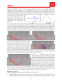
The following show the B-scan image and the corresponding photographs of the excavated duct at
location 1. The B-scan image shows a similar pattern for the empty duct and the grouted duct, which
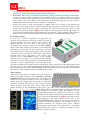
is a strong indication that the grouted duct is not fully grouted. The corresponding photo of the
excavated duct shows that the some of the strands are not embedded in grout. Thus the presence of
the air void is confirmed.
B-scan showing cross section image of slab at
location(1) with suspected void in grouted duct
The excavated duct at location (1) reveals that some of
the strands are not embedded in grout
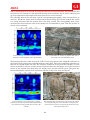
The following show the results at location 2. The B-scan image shows lower amplitude reflections at
the location of the grouted duct compared with the empty duct. These lower amplitude reflections are
from the 10 strands within the duct. The reflection coefficient at the grout-steel interface is lower
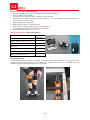
than at an interface with air, and that is why the grouted duct does not appear in red. The excavated
portion of the grouted duct shows that the strands were encased with the grout. The grout was
fractured during the removal of the metal duct and that is why a few wires are exposed.
B-scan showing cross section image of slab at
location (2) with no voids indicated in grouted duct;
the reflections in the grouted duct are due to the
strands.
The excavated duct at location (2) reveals that the strands
are encased with grout; note that some of the grout was
fractured in the process of removing the metal duct and
this exposed some wires.
101