1
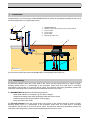
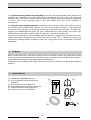
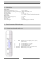
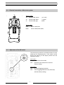
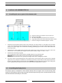
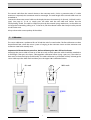
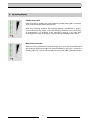
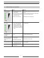
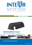
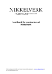
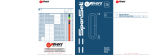
RAINMASTER D 24
Installation and user manual
WATER, WE’RE IN OUR ELEMENT
www.intewa.com
Table of contents
1. Introduction ......................................................................................................................................................................................... 2 1.1 Functionality .............................................................................................................................................................................. 2 2. Safety tips .............................................................................................................................................................................................. 3 3. Scope of delivery ................................................................................................................................................................................ 3 4. Technical Data ..................................................................................................................................................................................... 4 5. Electrical connections of the display device ............................................................................................................................. 4 5.1 Electrical connections of the display device ................................................................................................................... 4 5.2 Electrical connections of the sensor system ................................................................................................................... 5 5.3 Adjustment of the DIP switch .............................................................................................................................................. 5 6. Installation of the RAINMASTER D 24 .......................................................................................................................................... 6 6.1 Assembling the sensor system in the rainwater tank .................................................................................................. 6 6.2 Assembling the display device ............................................................................................................................................ 6 7. Calibration............................................................................................................................................................................................. 7 8. Operating display ............................................................................................................................................................................... 8 9. Trouble shooting in case of problems ......................................................................................................................................... 9 10. Maintenance ....................................................................................................................................................................................... 10 11. Replacement parts ............................................................................................................................................................................ 10 12. Contact .................................................................................................................................................................................................. 10 1
1. Introduction
Congratulations on your purchase of the RAINMASTER D 24, which we developed especially for the use of
rainwater applications in single-family homes.
1
0 0
1
0
9
2
1
2
3
4
5
6
%
0
8
0
7
0
6
5
0
0
4
0
3
0
2
0
1
0
AN
R
I MA T
SE
RD2 4
RAINMASTER D 24
Potable water refill unit with valve and inlet funnel
Sensor socket
Sensor cable
Quiet inflow
Backed-up water level
3
6
4
5
© INTEWA GmbH
System overview: Rainwater tank with RAINMASTER D 24 und potable water refill unit
1.1
Functionality
The fill-level indicator shows the water level in the cistern on the control device by means of lightemitting diodes (LEDs) as a percentage of the maximum water level. The water level is measured
contactlessly with the aid of a two-wire sensor cable. The capactive measuring procedure permits the
contactless recording of the current water level between the two sensor wires.
The RAINMASTER D 24 performs the following functions:
- Water level indicator in containers up to 2.80 m in height
- Automatic drinking water make-up feeding when the tank is empty
- Automatic protection feature against valve clogging
- Time-out of the valve outlet
The fill-level indicator shows the water level in the cistern on the control device by means of lightemitting diodes (LEDs) as a percentage of the maximum water level. The water level is measured
contactlessly with the aid of a two-wire sensor cable. The capactive measuring procedure permits the
contactless recording of the current water level between the two sensor wires.
2
The regulated drinking water make-up feeding occurs when the calibrated zero level is reached. The
solenoid valve connected to the valve outlet (power consumption 24 V DC / max. 15 W) opens and
drinking water is fed into the rainwater tank. The switching stroke for the make-up feeding is predefined
as approx. 2.5% of the measuring range, so that the drinking water flow occurs according to
requirements.
The automatic valve clogging protection is essential in areas with hard water. In the solenoid valve of
the drinking water make-up feed, deposits may form if the make-up feeding is only performed
occasionally. These deposits may impair the functioning of the valve in the long term. To prevent this
clogging, the RAINMASTER D 24 opens the valve automatically for a few seconds every three days
(deactivation by internal DIP switch possible). This performs a self-cleaning of the valve.
The time-out deactivates the valve switching output if the valve is triggered for more than two hours
without interruption (deactivation by internal DIP switch possible). This is intended to prevent the
unintentional make-up feeding of drinking water over a long period of time in the event of a device
malfunction.
2. Safety tips
Before installing the device, read these assembly and use instructions carefully. The information in these
instructions must be followed precisely; otherwise, all warranty claims will be invalidated. The operator is
responsible for observing the safety and installation requirements.
Installations on the drinking water supply network may only be performed by an approved installation
company.
3. Scope of delivery
[1] Indicator device RAINMASTER D 24
[2] Sensor socket with encapsulated sensor
electronics
[3] Sensor cable (two-wire, length 3m)
[4] Plug switching power supply 24 VDC/ 0.75 A
[5] Control cable (three-wire, length 20 m)
[6] Instructions for use (not illustrated)
[1]
[2]
100
90
%
80
70
60
50
40
30
20
10
0
RAINMASTER D 24
[5]
3
[3]
[4]
4. Technical Data
Display device:
Dimensions of control housing (H×B×T):
Power connection (plug switching power supply):
Operating voltage:
Valve power output:
Control cable:
125 x 67 x 35 mm
110-230 V AC /50-60Hz; 0.75 A
24 V DC
24 V DC / max. 15 W
20 m, ∅ 6 mm (3 x 0.5 mm²), prolongable up to 80 m
Sensor system:
Dimension sensor housing (∅ x H):
Operating voltage:
Sensor cable:
Sensor cable length:
90 x 57 mm
15 V DC
2 x Ø4 mm
3 m (shortening up to 1.2 m allowed)
5. Electrical connections of the display device
5.1 Electrical connections of the display device
Æ
INPUT:
Æ
Æ
Æ
S3:
S2:
S1:
Æ
Æ
OUTPUT V2:
OUTPUT V1:
Plug switching power supply, (24 V DC / 0,75 A)
(Center positiv)
Control cable, brown, (+15 V DC)
Control cable, black, (+ signal)
Control cable, grey, (GND)
Make-up feeding valve, (+24 V DC, max.15 W)
Make-up feeding valve, (GND)
4
5.2 Electrical connections of the sensor system
Sensor socket:
S3:
S2:
S1:
Control cable, brown
Control cable, black
Control cable, grey
(+15 V DC)
(+ signal)
(GND)
Sensor cable:
blue:
black:
Sensor cable, blue
Sensor cable, black (GND)
5.3 Adjustment of the DIP switch
The calcination protection and time limitation of valve
outlet can be deactivated by a DIP switch on the
board. The housing of the display device must be
opened to do this.
ON
1 2
DIP switch 1:
ON:
no time limit valve outlet
OFF: time limit valve outlet 2 hour activate
(factory setting)
DIP switch 2:
ON:
no valve clogging protection
OFF: valve clogging protection every three days
activate (factory setting)
5
6. Installation of the RAINMASTER D 24
6.1 Assembling the sensor system in the rainwater tank
A
B
C
D
S
Distance of the 0% level from the sensor cable end
Display range 0-100%
min. 20 cm safety distance from the max. water level
Safety distance from the inlet to the 0%level of min. 10 cm
Distance of weight from bottom (approx. 5-10 cm)
1.
Determine the installation position of the sensor housing in the dome shaft or in the upper tank area of the
cistern. The safety distance to the maximum water level is approx. 20 cm. The sensor cable hangs freely in the
tank over its entire length and is shortened accordingly. (Winding up the excess sensor cable distorts the
measuring result! )
2.
Determine the sensor length from the lower cable gland of the sensor housing to the sensor cable end.
Shorten with a 7 cm addition (cable length inside the sensor socket). Length = A + B + C + 7 cm.
3.
Determine the measuring range (B):
For the adjustment, make a mark at the 0% and 100% positions (e.g. insulating tape).
Minimum: At least 10 cm above the inlet to prevent the inward suctioning of air.
Maximum: The maximum level is generally the height of the cistern’s emergency overflow.
4
The sensor cables are pulled through the sealing plugs of the sensor housing and the cable ends are stripped
approx. 0.5 cm to crimp the enclosed wire end sleeves. Connect the sensor cable and the control cable to the
five-pin clamp. When doing so, observe the correct polarity. Carefully tighten the cap nuts of the cable gland
with an appropriate pair of pincers until the seal insert protrudes slightly from the cap nut.
6.2 Assembling the display device
The display device is intended for wall assembly. Remove the two upper screws on the housing, then
attach the wall bracket to the housing using the enclosed longer housing screws. Attach the device to the
wall with the enclosed dowel pins and screws.
6
The control cable from the control device to the rainwater tank is laid in a protective tube. If a cable
extension is required, this connection must be watertight. The total length of the control cable must not
exceed 80 m.
Connect the three-wire control cable on the display device to the terminals S3 (brown), S2 (black) and S1
(grey) (see page 4). To do so, simply press the cable with the stiff cable end sleeves into the
corresponding socket. The cable is clamped in place by the internal spring mechanism, i.e. the cable can
no longer be loosened by pulling on it. To loosen it, the white button above the clamp must be pressed
to release the wire.
Always observe the correct polarity of the cables!
7. Calibration
The sensor calibration is performed first of all with the aid of a water bucket. The fine calibration can then
be performed later, when the sensor system is hanging in the rainwater cistern and the minimum and
maximum water levels actually exist.
Important: Calibrate the zero point first, before calibrating the 100% fill level indicator.
Submerge the sensor cable in water up to the 0% mark, at which point the cable should be stretched to
its full length. Then press the lower, submerged 0% calibration button (using a pen, etc.). The value has
been read in when the display flashes briefly. The 100% calibration is performed similarly: Submerge the
sensor cable up to the 100% mark and then press the upper 100% calibration button.
0% mark
100% mark
7
8. Operating display
Potable water refill
If the zero level is reached, the valve outlet for potable water refill is activated,
and is indicated by the illuminated red LED.
Note: The switching stroke for the make-up feeding is predefined as approx.
2.5% of the measuring range, so that the drinking water flow occurs according
to requirements. For example, if the measuring range B = 2 m, then after
reaching the 0% water level, approx. 5 cm of make-up drinking water is fed in
Max. fill level indicator
With an increasing fill level, all of the LEDs light up as far as the current fill level. If
the maximum water level (100%) has been exceeded by 10%, this is shown by a
flashing 100% LED. You can then recalibrate it using the 100% calibration button.
8
9. Trouble shooting in case of problems
Error
Cause
Solution
All LEDs blinking
simultaneously
a.) incorrect polarity of the
control cable
a.) Check the polarity on the control and sensor
sides
b.) The valve output has been b.) Reset by pulling out the power supply plug
until all of the LEDs turn off
permanently activated for
more than 2 hours
c.) faulty sensor electronic
c.) Replace the sensor electronic
0+10% and 90 +100%
LEDs shine
This display is active if the
entry via the calibration
buttons is incorrect, for
example when the lower
calibration value is higher
than the upper calibration
value.
Calibrate a new value and / or recalibrate the
second value
Drinking water makeup feeding is not
activated
0% calibration is set too
low
Raise the make-up feeding level by pressing
the 0% calibration button
When water touches
the sensor cable, the
display jumps up to
100%
a.) Incorrect polarity of the
sensor cable
b.) Damaged sensor cable
a.) Correct the sensor polarity
b.) Replace the sensor cable
On activating the
valve, the LEDs turn off
Alternating-current valve
connected and/or current
consumption too high
Connect a DC valve with max. 15 W power
consumption
No LED display
The power supply is
interrupted
Check the plug switching power supply
9
10. Maintenance
Once a year the entire system hast to be checked on its operational reliability. For this purpose the sensor
cable is pulled out of the water to control the correct indications on the display.
11. Replacement parts
Replacement parts can be ordered by indicating the serial number. The identification number is
displayed on the backside oft he unit.
Index no.
(see chapter 3)
Order code
Indicator device RAINMASTER D 24
[1]
RMD 24 A
Sensor socket with encapsulated
sensor electronics
[2]
RMD SE3
Sensor cable 3 m
[3]
RMD S3
Power supply unit 24 V, 0.75A
[4]
RMD N EU
Control cable per m
[5]
RMD STK
Article description
12. Contact
For customers in Germany:
For any queries, ordering of spare parts, as well as in case of service, kindly contact INTEWA GmbH
directly, quoting your product‘s model and identification numbers and the purchase invoice details, at:
INTEWA GmbH
Jülicher Straße 336
52070 Aachen
Tel.: 0049-241-96605-0
Fax: 0049-241-96605-10
Email: [email protected]
Internet: www.intewa.de
For customers in other countries:
For any queries, ordering of spare parts, as well as in case of service, kindly contact your installer or the
authorised importer, quoting your product‘s model and identification numbers, and the purchase invoice
details.
10
© INTEWA GmbH
Version: 2.2
Technical modifications reserved.
11