1
INTEWA DRAINMAX® Tunnel
Technical documentation and application
WATER, WE’RE IN OUR ELEMENT
0
www.intewa.com
Table of contents
1 Introduction ........................................................................................................................................ 2 1.1 Range of application .................................................................................................................. 3 2 Product description ........................................................................................................................... 4 2.1 Technical Data ........................................................................................................................... 6 2.2
3 4 Transportation and mounting ..................................................................................................... 8 Instructions for layout, planning and execution of infiltration and retentions systems ............ 9 3.1 Instructions for layout ................................................................................................................ 9 3.2 Instructions for pre-treatment of rainwater ...............................................................................10 3.3 Instructions for inspection and cleaning devices ......................................................................11 3.4 Instructions for pipe installation and ventilation of system .......................................................12 Installation instructions ...................................................................................................................15 4.1 Base layer and equalizing layer................................................................................................15 4.2 Backfilling materials and backfilling of the tunnel system ........................................................15 4.2.1 Backfilling with non-binding material...............................................................................16 4.2.2 Backfilling with 16/32 mm gravel ....................................................................................17 4.3 Covering and load bearing capacity of the tunnel system ........................................................18 4.3.1 DRAINMAX Tunnel/60 with DIBt approval .....................................................................18 4.3.2 Object-specific calculation for special edge condition ....................................................18 4.4 Overview of construction with paved traffic areas as per RStO 01 .........................................19 4.5 Load capacity during installation ..............................................................................................20 4.6 Filter fabric ................................................................................................................................22 4.7 Compound filter fabric at the base of flushing tunnel ...............................................................23 5 Overview of installation steps .........................................................................................................24 6 Service ...............................................................................................................................................26 6.1 Inspection and Maintenance.....................................................................................................26 6.2 References ...............................................................................................................................27 6.3 Warranty and manufacturer’s guarantees ................................................................................27 1
1
Introduction
Infiltration and attenuation of rain water has increasingly become the focus of public interest in
past few years. Floods, falling ground water level as well as overloaded and outdated sewer
systems in many regions has led to an increased importance of local water management system.
Increasing environmental awareness of the natural infiltration of rainwater and economic constraints in many states has accordingly led to numerous government regulations and amendments for local rainwater management.
In NRW, the state water law requires infiltration of rain water on the grounds of new
buildings
In several countries and municipalities, the subsequent installation of local water management systems is required.
In a large number of municipalities, a fee has to be paid due to the sealed surface in order to increase the incentive for local infiltration.
If a local infiltration rainwater is not possible, then in several cases, the temporary attenuation
(retention) of rainwater is necessary in attenuation areas. It is protected against overloading by
means of a throttled discharge into the connecting drainage system or it is constructed with a
smaller size.
The advantages of local rainwater management for municipalities are:
Reduced expenditure on flood protection / flood prevention
lower costs in construction of drainage system, the drainage rehabilitation and in using
treatment plant
Less development of costs for new housing areas
Provision of basic water supply
As manufacturers, the INTEWA GmbH has specially developed the DRAINMAX® tunnel system
for infiltration, attenuation and storage of rainwater. The tunnel system built underground minimizes the expenses for creation and operation of the rainwater management system. Due to
its flexibility, the DRAINMAX® tunnel system is used as a solution for drainage of rainwater ranging from individual buildings to large commercial properties.
This documentation serves as the base for the production engineers and fabricators alike. As
long as the fabricator complies with the below mentioned installation guideline, then maximum
service life and safety of the system is guaranteed.
This documentation corresponds with the current state of technology, but makes no claim to
complete. Technical changes are also reserved.
2
1.1
Range of application
The INTEWA DRAINMAX® tunnel system is specially designed for underground infiltration, attenuation
and storage of rainwater. The system can be used alike in small drainage tasks up to huge applications
in commercial and industrial sectors.
Using the tunnel system for trench infiltration
The rainwater infiltration allows infiltration of rainwater at source.
Some of the advantages of infiltration are:
The rainwater is recycled back into the natural water cycle
Decoupling from the drainage system and
thereby exemption from the fee due to sealing charged in several places
Fig. 1: Trench infiltration
Using the tunnel system for pit - trench infiltration
Mulde
As a general rule, the combination of pit infiltration
and trench infiltration is done when:
an infiltration is required
called busy ground zone
the space required for
pit has to be minimized
a
by
the
so-
commercial
Fig. 2: Pit – trench infiltration
Using the tunnel system for rainwater attenuation
With attenuation, the rain water is temporarily
stored in the tunnel system and is throttled via a
special drainage device to the drainage system.
Reasons for attenuation may include:
Connecting additional sealed surfaces
existing drainage systems
Municipality order, for example, if the local
soil conditions do not allow infiltration
Reduction of peak drainage flows in the
drainage system during heavy rainfalls
3
to
Fig. 3: Rainwater attenuation
2
Product description
The INTEWA DRAINMAX ® system elements are designed for underground installation. The
rainwater is directed into the created underground storage reservoir for infiltration or temporary
storage.
The load of earth and transportation is directed into the surrounding ground soil due to
the vault-shaped design of the INTEWA DRAINMAX® tunnel. The prerequisite load bearing
capacity is the loading of tunnel body on to the ground by backfilling sides.
The DRAINMAX® tunnel can be used below traffic zone with heavy load up to SLW60 depending on the type of backfilling (gravel or consolidated soil material) and the amount of cover. The
height above ground can be lie within the range from 50 to 200 cm above the tunnel shoulder
(Chap. 4.6).
The water is uniformly divided and infiltrated in the ground without any obstructions by means
of the completely open interior of the tunnel. The boring rows on both sides for two height levels
ensure infiltration even from the potentially necessary infiltration from sides.
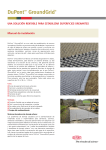
The INTEWA DRAINMAX® system elements are:
- Start section (with 4 cm small connecting serrations)
- Central tunnel (on one side with an 8 cm wide connecting serration and on the other
side with a 4 cm small connecting serration)
- End section (with an 8 cm wide connecting serration)
1. End section DRAINMAX-T100E/60
2. Middle tunnel DRAINMAXT1600M/60
3. Connection markings
4. Start section DRAINMAX-T100S/60
5. Air vent connection
Fig. 4: DRAINMAX Tunnel
4
The INTEWA DRAINMAX® tunnel elements are manually laid in rows. A distance of 450 mm
must be maintained with a parallel installation of rows.
The elements of start section, the middle tunnel and the end section are added together in a row
and a closed system is provided by the connecting serrations overlapping and fitting each other
with face-up position.
The connecting pipes for water intake and discharge as well as for evacuating the air are installed at the start and end section of the tunnel row. You can install a pipeline connection ranging from DN100 to DN300 in both lower and upper region.
The DRAINMAX tunnel elements must be installed as per the installation guidelines mentioned
below. The DRAINMAX tunnel elements are then laid for a service life of 50 years with respect
to their material characteristics and their scope of use.
The installation varieties other than these need a separate structural calculation.
The elements are made from polyethylene (PE-HD) with cupping process. This technical plastic is resistant to chemicals and microorganisms and thus does not rot. The variety of pure plastic is also 100 % recyclable.
Warning instructions:
-
The tunnel elements may not be committed from within.
The following installation guidelines are crucial for installation.
The tunnel elements may not run over by site vehicles just after a consolidated minimum
covering.
The specific planning specifications are to be observed.
5
2.1
Technical Data
Middle tunnel
DRAINMAX parts
Start section
End section
DM-T-1600-M/60
DM-T-100-S/60
DM-T-100-E/60
Length
2340 mm
443 mm
444 mm
Width
1375 mm
1375 mm
1375 mm
Height (corrugated shoulder)
781 mm
767 mm
736 mm
Height (Dome connection)
805 mm
--
--
effective used length
2250 mm
--
--
HGV60
HGV60
HGV60
Weight
32 kg
5,5 kg
5,6 kg
Material
PE-HD
PE-HD
PE-HD
1 x DN100 (Dome)
DN100-300
DN100-300
± 4%
± 4%
± 4%
+2 to + 30°C
+2 to + 30°C
+2 to + 30°C
1,6 m³
0,1 m³
0,1 m³
Load class
Connections
Approved tolerance
Approved processing temperature
Storage volume
Tab. 1: Technical data of the DRAINMAX tunnel elements
6
Fig. 5: Dimensions of the DRAINMAX® tunnel elements and connetion markings
7
2.2 Transportation and mounting
The elements of DRAINMAX® Tunnel are packed on pallets or delivered as packaged goods to the
site. There on site, they are unloaded manually, lifting truck or other lifting aids. The starts section and
end section generally transported below the middle tunnels.
Image 1: Pallet transportation of the Tunnel elements
Image 2: Lifting the elements
The temporary storage must be done on the special delivery pallets. With risk of high winds,
the piled tunnel elements must be secured with straps.
The DRAINMAX® Tunnel can be stored outdoors. But then you have to protect them from direct sunlight and heat by using a bright, opaque covering. The storage time should not exceed one year.
Warning
The tunnel elements may be damaged due to inappropriate handling. The impact load is to be
avoided particularly in cold weather.
Lorry 40 t,
Trailer truck
Palett
45 FT HC Container
(Ocean fright)
Dimensions (L x W x H)
2,34 x 1,40 x 2,20 m
13,6 x 2,46 x 2,55 m
max. Number of pieces
20 Tunnel = 1 palett*
180 Tunnel = 9 pallets 225 Tunnel = 9 paletts*
Loading weight
of max. Number of pieces
690 kg
6210 kg
7650 kg
Gross storage volume
(without sections)
32 m³
288 m³
360 m³
*In maximum 5 start- and 5 end sections can packed together with each pallet
Tab. 2: Transportation dimensions and weight of DRAINMAX Tunnels
8
13,56 x 2,35 x 2,70 m
3
Instructions for layout, planning and execution of infiltration and retentions systems
The knowledge of local geological and hydrological conditions which can be examined by experts must be known. The infiltration area has to be examined with respect to the type of soil,
ground water condition (even in terms of increased ground water as a result of infiltration) as
well as permeability and stability by the Geotechnical Engineer especially with infiltration systems.
Moreover, following legal regulations and technical directives have to be observed for the construction of rainwater management systems:
Legal regulations
Technical directives
-
EU-law
-
Work Sheet DWA-A 138
-
Federal law
-
ATV-DVWK-M 153
-
Federal State Law
-
DWA-A117, A118, A121, A128
-
Municipal Statutory Law
-
KOSTRA
-
Various standards: including DIN4261-1, EN 752
Tab. 3: Overview of legal regulations and technical directives
Technical and construction restrictions related to drainage water technology are to be inquired
to the responsible authorities.
3.1
Instructions for layout
The layout of the rainwater management systems usually includes the steps listed below:
-
Inventory control and assessment of the connected, fixed surfaces
-
Calculating the amount of inflow as well as infiltration and attenuation system
-
Calculation of infiltration runoff (the runoff with attenuation system will be firmly defined
by the specified throttle runoff value)
-
Iterative determination of the required storage volume depending on the local rainfall and frequency of overflow events
-
Assessment and selection of the most economical system design
-
Specifying the design: The number of tunnel and arrangement, type of backfilling material
-
If necessary, determining the pre-cleaning measures, flushing and inspection chambers, mounting material, etc.
The INTEWA GmbH will gladly support you with planning and design. This also includes support for hydraulic proof by software – supported simulation.
.
9
3.2
Instructions for pre-treatment of rainwater
The water supplied by DRAINMAX® system requires a sedimentation and filtration in order to
ensure the proper functioning of the infiltration system or the attenuation system.
Regular inspections, maintenance and cleaning by this pre-treatment fixtures ensure a smooth
operation of the tunnel system primarily with respect to a uniform infiltration performance
and the protection of the throttle device with the attenuation systems.
For infiltration systems, the sizing and selection of water pre-treatment fixtures also emphasises
more on the expected concentration of material and thereby if necessary, associated hazards of
groundwater.
The load of underground water and above ground water can be evaluated qualitatively and
quantitatively with the help of simple evaluation methods by rain water from roofs and traffic
zones. (The appendix A to C of the ATV-M153 allows a full and detailed assessment of precleaning measures.)
Depending on the result and various measures for rainwater treatment, a sufficient protection of
water has to be ensured. The INTEWA GmbH will gladly support you with planning and design.
Fig. 6: Example: Sedimentations slot and filter slot for cleaning rainwater
10
3.3
Instructions for inspection and cleaning devices
You can inspect it fully due to the fully open half-shell design of the tunnel element and if necessary, it can also be cleaned. You just have to connect the row of flushing tunnel to a flushing
chamber and inspection chamber. From here, you can direct a rotary – swiveling camera or
cleaning nozzle in the system and the dirt can be removed from the system.
Flushing and inspection pit
Fig. 7: Camera inspection by the inspection pit entrance
Due to well-sized application of the preliminary sedimentation system, usually a regular cleaning of the infiltration trench is not required. However, you can carry out clean in case of emergency with appropriate precautionary measures such as arrangement and the number of flushing and inspections chambers as well as the special layout of the flushing tunnel row are to be
taken into consideration in the planning phase.
Generally, cleaning is done only when it is recommended in an inspection report that too much
sedimentation has been deposited or if the infiltration capacity is reduced significantly.
Hochdruckschlauch
High pressure
hose
Suction lance
Sauglanze
Flushing
inspection pit
Spülund and
Kontrollschacht
Fig. 8: Cleaning and slime removal via flushing and inspection pit
11
Then the bottom of the tunnel is cleaned by means of a high pressure cleaning nozzle in the
tunnel row deployed as the flushing tunnel. The cleaning nozzle of the flushing truck is directed
towards the flushing and inspection pit in the flushing tunnel. The reverse jet of the cleaning
nozzle cleans the sedimentation settled at the bottom of the flushing pit and inspection chamber which is from here sucked through suction lance. Several cleaning and rinsing cycles may
be required depending upon the dirt.
Image 3: Flushing nozzle with reverse conical jets
3.4
Image 4: Flushing nozzle with cleaning procedure
Instructions for pipe installation and ventilation of system
The pipes are connected as per the specifications in plan from the head end of the
tunnel to the start and end sections. The
pipe connection markings at the tunnel
section allow on-site cutting by means of
a sabre saw. The inlet pipe of the rainwater into the tunnel system can be introduced at the level of tunnel shoulder or
tunnel bottom.
Fig. 9: Connection markings of the start and end section
12
The inflow into each row of tunnel is usually done at the pre-cleaning fixure via an appropriately
connected piping system. In case of several rows, the volume flow rate of inflow is equally distributed in all rows of tunnels.
DR AI N- MAX ®
INTE WA
DR AI N- MAX ®
INTE WA
DR AI N- MAX ®
INTE WA
D RAI N-MA X ®
INT EWA
D RAI N-MA X ®
INT EWA
D RAI N-MA X ®
INT EWA
DRA IN -MA X ®
I NTEWA
DRA IN -MA X ®
I NTEWA
DRA IN -MA X ®
I NTEWA
DRA IN -MA X ®
I NTE WA
DRA IN -MA X ®
I NTE WA
DRA IN -M AX ®
I NTE WA
Fig.10: Example for connected piping system to the preliminary sedimentation and filter pit
If a flushing tunnel is used, the water is distributed at the end of flushing tunnel row into parallel
tunnel rows.
> 1m
© INTE WA GmbH
HGW
Sedimentation
INT EWA
D RAI N-MAX ®
INTE WA
DR AI N-MAX ®
INTE WA
DR AI N-MAX ®
andentations
filter pit- und
Sedim
Filterschacht
Flushing
and
inspection
Spül- upit
nd
Kontrollschacht
DRA IN -M AX ®
I NTE WA
I NTE WA
DRA IN -MAX ®
I NTE WA
I NTE WA
DRA IN -M AX ®
DRA IN -M AX ®
I NTE WA
I NTE WA
DRA IN -MA X ®
DRA IN -MA X ®
Geoverbundstoff-Unterlage
Filter
fabric base at row
der Spültunnelreihe
of flushing tunnel
Spültunnel
Fig.11: Example for inflow connection of the parallel tunnel rows by using a flushing tunnel
13
The variations in air pressure caused in the tunnel system by inflow and discharge of the water
must be balanced by ventilation. The size of vent is based on the maximum volume flow rate of
inflow. A venting connection is provided in DN100 depending on the inflow amount 20 l/s.
The venting connection from tunnel is done from the centre of tunnel dome or from the top of
section connection. The air is transferred outside via a vent of air to the outside via a ventilated
pit (such as, sedimentation pit or flushing and inspection pit).
Vent of air
Ventilation
Flushing and inspection pit
Fig. 12: Example for venting possibility
14
4
Installation instructions
The professional installation of the tunnel elements is a prerequisite for proper functioning and
long service life of the entire system. This affects the entire construction phases right from the
preparation of plan to backfilling up till the covering of the tunnel system.
4.1
Base layer and equalizing layer
The load bearing capacity of the existing soil is necessary for obtaining the stability of the tunnel system. If there is lack of knowledge or doubt related to the load bearing capacity of the
soil, then a special investigation is necessary by a Geotechnical Engineer. If the load bearing
capacity of natural soil is not sufficient, then if necessary, the required load bearing capacity
can be established by advanced measures (for example, gravel base layer, filter fabric insert etc.).
A non-binding, consolidating soil material may be used as a base layer cannot cohesive, compressible soil material can be used up till gravels with a grain size up to 16/32 mm. The contact
patch of the tunnel must indicate a load bearing capacity of at least Ev2 ≥ 45 MN/m².
For infiltration purposes, the permeability of the consolidated underground soil must at least
correspond with the permeability as specified in the plan.
4.2
Backfilling materials and backfilling of the tunnel system
The tunnel system can be backfilled with a permeable, non-binding and consolidating soild material up to 16/32 mm gravel, depending on the required load bearing capacity of the entire system. Generally, the tunnel system can be loaded with a consolidated backfilling with at the
highest.
Regardless of the backfilling material, the backfilling is even and on both sides in layers of 20
cm.
Attention
One sided backfilling is not permitted, since this can lead ti deformation of the tunnel structure
and minimizes the capacity of the system.
Fig. 13: not permitted, one sided backfilling
15
4.2.1 Backfilling with non-binding material
If the backfilling is to be done with non-binding backfilling material with fells, then the tunnel
elements must be directly covered with a GRK 5 filter fabric in order to prevent the penetration
of fells into the infiltration holes on sides.
The minimum cover above the tunnel shoulder is specified as fixed 35 cm. Hereby, the load
bearing capacity EV2 = 45MN/m² required for track superstructure as per RSTO 01 is to be established.
The backfilling from sides and top occurs in layers with max. 20 cm with appropriate consolidation. (The compacting requirements of ZTV E-StB 09 are to be observed under traffic zones
ower traffic areas of compaction requirements are noted ZTV E-StB 09)
Superstructure/Trafficzone
Filter fabric
Notice: The allowed minimal and maximum height D is addicted by the installation situation and traffic load (Chap. 4.3)
Fig. 14: backfilling with non-binding, consolidating soil material (SLW30 congestion)
The backfilling material as well the required load bearing capacities of the construction layer
are to be referred from the following table.
Construction layer
A, C
Material
Load bearing capacity
Dpr ≥ 97%
Base and equaliizing Non-binding, consolidating material with
min. EV2 = 45MN/m²
layer
soil class 3 and 4 as per DIN 18196
B
Backfilling of tunnel
from sides and top
Non-binding, consolidating material
as per DIN 18196
(consolidation of up to 20 cm each)
Dpr ≥ 97%
C
Tunnel covering
Non-binding, consolidating material
as per DIN 18196
(consolidation of up to 20 cm each)
Dpr ≥ 97%
min. EV2= 45MN/m²
Tab. 4: Construction layers with backfilling tunnel using non-binding material
16
4.2.2 Backfilling with 16/32 mm gravel
The backfilling with gravel is a kind of construction for creating additional infiltration volume by
void proportion of the gravel. The characteristics related to installation of filter fabric and establishing traceable load bearing capacity is to be observed with backfilling.
The direct covering of tunnel rows with filter fabric is not mandatory with 16/32 mm gravel,
since as this size of particles cannot enter through the side holes. In order to prevent the submerging of surrounding soil into the gravel bed, it is necessary to cover it with filter fabric from
all sides. For obtaining the required load bearing capacity of EV2 = 45MN/m², a consolidated
layer of at least 25 cm must be introduced with non-binding and consolidated material on 10 cm
tunnel cover. A plane intermediate layer of filter fabric protects the gravel bed from penetration
of fells.
Superstructure/Trafficzone
Filter fabric
Notice: The allowed minimal and maximum height D is addicted by the installation situation and traffic load (Chap. 4.3)
Fig. 15: Construction layers with tunnel backfilling using 16/32 gravel (SLW30 congestion)
The backfilling material as well the required load bearing capacities of the construction layer
are to be referred from the following table.
Construction layer
A
B
C
C*
Material
Load bearing capacity
Base and equaliizing
layer
Tunnel backfilling
from sides and top
( ≥ 10 cm)
Non-binding, consolidating material
As per DIN 18196
min. EV2 = 45MN/m²
Dpr ≥ 97%
Crushed gravel
16/32 mm gravel
Dpr ≥ 97%
Tunnel covering
( ≥ 25 cm)
With firm surfaces:
Non-binding, consolidating material
As per DIN 18196
Dpr ≥ 97%
min. EV2 = 45MN/m²
Tunnel covering
With loose surfaces
(such as pit – trench infiltration):
Ground with permeability requirements
as per DWA-A138
Kf >= 1 x 10⁻⁴ m/s
Low consolidating installation
max. Dpr =92%
Tab. 5: Construction layers with backfilling using 16/32 gravel
17
4.3
Covering and load bearing capacity of the tunnel system
The load bearing capacity of the installed tunnel system is in
addition to the bearing capacity of the contact patch depends on the backfilling materials on sides, the degree of
consolidation as well as the entire covering height (P).
The better the consolidation, that much better will be the
load transfer. The greater the traffic load, the greater the
distribution of load by an appropriately specified construction height.
The following table mentions the load bearing capacity. The
entire cover (P) above tunnel shoulder is to be maintained
depending on the traffic load, regardless of the type of superstructure and road surface.
Fig. 16: Total overlying ground P
4.3.1 DRAINMAX Tunnel/60 with DIBt approval
max.
axle load
Possible total overlying
ground P
--
0.501 – 3.00 m
12 t Lorry
(alternative surface load = 6.7 kN/m²), gravel surface
8.0 t
0.501,2 – 2.75 m
Heavy goods vehicle HGV 30
(alternative surface load = 16.7 kN/m²), paved surface
13.0 t
1.00 – 2.00 m
Heavy goods vehicle HGV60
(alternative surface load = 33.4 kN/m²), paved surface
20.0 t
1.00 – 1.65 m
Installation situation / working load
Accessible gravel surface
1
2
Valid only if the installation range is reported as frost-proof.
The formation of lane grooves has to be considered at unhitched areas. The minimum total cover may not be exceeded!
Tab. 6: Overview of the allowed total overlying ground (Traffic loads according to DIN 1072) with special
manufacturing
4.3.2 Object-specific calculation for special edge condition
This user guideline describes the relevant standardised installation conditions. The installation and edge
conditions different from it are not covered by the existing structural standards.
The INTEWA GmbH will be glad to assist you with the
project-related 3D FEM simulation by means of object-specific structural standards.
Fig.17: Determining the installation depth
18
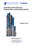
4.4
Overview of construction with paved traffic areas as per RStO 011
The DRAINMAX® Tunnel is approved for installation under parking areas including heavy traffic. This corresponds to the classification of construction class BK V according to RStO1 01.
The traffic surface can be made in asphalt, concrete or plaster. The segmentation in structural
level can be determined on the basis of construction class (type of traffic load) depending on
the type and thickness. The load bearing capacities of the structural layers are defined by respectively associated deformation Ev2.
Superstructure /
Traffic zone
Base layer with
DRAINMAX tunnel
Fig. 18: Example of base layer / superstructure with bituminous cover in accordance with RStO
classification V, Line 3.11
A = Sustainable ground layer
B = Filling, for instance, with gravel 16/32 mm
C = Tunnel covering (45MN/m²)
D = Anti-freeze layer (45MN/m²)
E = Ballast substructure (120MN/m²)
F = Bituminous base layer (150MN/m²)
G = Binding layer
H = Covering layer
P= Total overlying ground
1
Official German guidelines for the standardization of traffic surfaces
19
4.5
Load capacity during installation
The open half-shell structure is structurally loose without side and top backfilling. By the deformations due to high installation loads are avoided this way. Usually, the direct driving of the
tunnel elements with construction vehicles or with consolidating devices is not allowed.
Height specification
Consolidating device
(1)
0 to 50 cm
above ground level
vibrating plates:
Operating weight:
Plate width:
Vibrating force:
Vibrating frequency:
approx. max. 100 kg
380 mm x 500 mm
12 kN
85Hz
(2)
50 to 120 cm
above ground level
Vibrating plates:
Operating weight:
Plate width:
Specific support pressure:
Vibrating force:
Vibrating frequency:
approx. 255 kg
600 mm x 800 mm
0.86 since N/cm²
35 kN
80Hz
(3)
from 40 cm
above tunnel shoulder
e.g. Vibrating plates:
Operating weight:
Plate width:
Vibrating force:
Vibrating frequency:
approx. 400 kg
450 mm
59 kN
65Hz
(4)
from 80 cm
onwards above tunnel
shoulder
e.g. Vibrating plates:
Operating weight:
Plate width:
Vibrating force:
Vibrating frequency:
approx. 760 kg
700 mm
100 kN
56Hz
Tab. 7: Consolidating device for backfilling from sides and top
Attention
The compression may only be done with plane vibratory plates. Vibrating tamper and vibratory rollers are
not permitted!
20
Height specifications
Construction vehicle
- starting from 40 cm compacted covering on tunnel
shoulder
Crawler exacavtor
- Total weight max. 20 t
- Spare distributed load < 5 KN/m²
- starting from 60 cm compacted covering on tunnel
shoulder
Wheeled vehicle
- starting from 80 cm compacted covering on tunnel
shoulder
- with max. Wheel load of 4 t, that may not exceed
by dumping
- Spare distributed load max. 6,7 KN/m²
Wheeled vehicle
- with max. Wheel load of 6.5 t, that may not exceed by dumping
- Spare distributed load max.16,7 KN/m²
Tab. 8: Permitted load of construction vehicle during tunnel installation
Fig. 19: Overview of construction machines and vehicle
21
4.6
Filter fabric
The filter fabric is used whenever there is a risk of fells entering into the tunnel.
Filter fabric
When backfilling with non-cohesive material, then the tunnels
are to be covered with filter fabric. An oversized filter fabric
must be placed on the tunnel rows, so that it can follow the
serrated structure and could be filled completely with soil in
serrated area during backfilling. The overstretching of filter
fabric is to be avoided in cavities.
The fabric must have a minimum width of 2.5 m for direct
covering of tunnel.
Fig. 20 covering of the Filter fabric
It is not necessary to directly cover the tunnel rows with filter
on the tunnel rows
fabric while backfilling it with 16/32 mm gravel. Here, the filter
fabric is possibly used only as a separating layer to the final earth covering.
The tunnel bottom is generally covered with filter fabric or geocomposites (flushing tunnel).
If pipes are directed through the filter fabric, then the fabric is to be cut at the appropriate place
with undersize, so that the pipe can be tightly routed through the cuts. Overlaps must be directed with at least 50.
The used filter fabric must fulfill following requirements:
Filter fabric sturdiness class:
Minimum width:
Stamping push through force:
Max. tensile strength longitudinal / diagonal:
Max.expension longitudinal / diagonal:
Opening width:
Water permeability VIH50:
GRK 5
2.5 m
3500 N, as per EN ISO 12236
24 / 28 kN/m as per EN ISO 10319
70 / 80%
0.06 mm
36 l/sm2
22
4.7
Compound filter fabric at the base of flushing tunnel
For applications in which it is possible to clean the base of the tunnel, the INTEWA compound
filter fabric GVS 500 is installed in the bottom area of the rows of flushing tunnels.
This later allows efficient cleansing of the sediments settled at the tunnel base. The compound
filter fabric has a non-woven fabric on one side and mesh on the other. The mesh is installed
from top facing up. The flushing tunnel rows are installed on the mesh side. The backfilling of
tunnel system is done with fell or gravel from sides as described.
The compound filter fabric is laid in the channel within the flushing tunnel. There must be no
overlappings. The compound filter fabric must extend to at least 300 mm on the sides in order
to be appropriately clamped in the soil. The adjacent tunnels must maintain an appropriate distance.
Flushing bottom with compound filter fabric
Fig. 21: Compound filter fabric in bottom area of the flushing tunnel
The used compound filter fabric must fulfill following requirements:
Filter fabric sturdiness class:
Minimum width:
Stamping push through force:
Max. tensile strength longitudinal / diagonal:
Max. tensile strength expansion
longitudinal / diagonal:
Opening width:
Water permeability VIH50:
GRK 5
2m
6500 N, as per EN ISO 12236
45 / 45 kN/m as per EN ISO 10319
7 / 7%
0.08 mm
7.5 mm/s
23
5
Overview of installation steps
Construction pit and ground level
The construction put is to be created as specified in the
plan. In doing so, the DIN 18300 ("Groundwork operations"), DIN 4124 ("construction pits and ditches, embankments, pit lining") and if necessary, DIN 4123
("building security within the scope of excavation") are
to be observed.
- Establishing a horizontal, even and stable base layer
(for infiltration purposes, the permeability of the compacted subsoil must at least correspond with the permeability mentioned in plan specifications.)
- A separating layer of filter fabric is used installed at
ground level and at embankment of construction pit
when using 16/32 mm gravel as backfilling material.
When the backfilling material is non-cohesive, the tunnel has to be covered all-over with filter fabric.
- The filter fabric is placed under the row of
tunnel
Image 5: Ditching the pit
Image 6: dyn. Plate load test at
ground level
- The ground level is to be created with examination of
the load baring capacity as mentioned in the plan
specifications.
Laying the tunnel elements and establishing pipe
connections
Image 7: Filter fabric on bottom area
Before the tunnel is laid, the inflow and inspection pits
must be installed at the appropriate position and height
and the tunnel bottom must be strengthened by filter
fabric.
- Place the DRAINMAX elements on the prepared
ground in rows with placed filter fabric.
- The first tunnel is laid down starting from the intake pit
with start section. The elements are connected with
each other by overlapping. The end cap closes the
tunnel row. After this, place the next row parallel as
per the distance specified in the layout plan.
Image 8: Line to inflow pit
Image 9: Form lock fixing of two tunnel elements by overlapping
24
- Cover rows of tunnel with filter fabric and arrange it in such a way that the fabric can adapt
to the serrations when covered with soil. Avoid
overstretched fabric at cavities. (If using 16/32
gravel, the rows of tunnel are not required to be
covered directly.)
- Secure foot embankment with soil in order to fix
filter fabric.
.
Backfilling of tunnel elements from sides
The tunnel element is backfilled from both sides
and top with suitable backfilling material in uniform
layers of maximum 20 cm
Image 10: Covering with filter fabric
- The uniform compacting of backfilling layers is
done with light consolidating device. With increasing altitude heavy consolidating devices
may be used (see Chapter 4.4)
Covering the tunnel elements
The load bearing capacity for connected road superstructures is to be taken into account while
convering the tunnel elements.
Image 11: Backfilling filter fabric for fixing
- The backfilling material with mixed grading
curve is consolidated in layers above the tunnel
shoulder up till the required load bearing capacity is obtained.
- When using 16/32 mm gravel, it is backfilled up
to 10 cm above the tunnel shoulder backfilled
and is covered flat with a separate layer of filter
fabric. The filter fabric is beaten down from all
sides (at least 50 cm overlapping). It is further
backfilled and compacted in layers with nonbinding soil material till the required capacity of
45 kN/m² is attained.
Image 12: Compacting with a small compacting device between rows of tunnel
Superstructure for paved road surfaces
Finally, the superstructure is created for the road
surfaces as per plan specifications.
Image 13: Covering the tunnel elements
25
6
Service
6.1
Inspection and Maintenance
The upstreamed rainwater cleaning systems are to be regularly maintained and cleaned. You
can obtain details on maintenance of INTEWA sedimentation and filter pits at www.intewa.de.
One advantage of the DRAINMAX tunnel system is its open hollow structure. You can completely inspect and flush the bottom and wall of the tunnel by suitable connection pipe, which
are both critical for long term infiltration performance.
The infiltration capacity can be recorded and examined by measuring the change in water level.
If the infiltration capacity deviates more than 25 % of the output, then the cause has to be determined by a camera inspection, for example, the thickness of sedimentation has to be
checked.
The area of flushing tunnel can be cleaned and the sediments can also be removed by using
the high pressure cleaning procedure consisting of jet nozzle. Local drainage cleaning companies have the necessary equipment for extraction, rinsing and cleaning this. You can
find detailed information on the inspection, maintenance and remote monitoring system at
www.intewa.de .
Image 14: Image: Drainage cleaning system
Image 15: High pressure cleaning
The throttle system has to be checked for free movement and permeability with attenuation
systems. You can find detailed information on INTEWA products at www.intewa.de
26
6.2
References
The INTEWA DRAINMAX tunnel is extremely popular in the country as well as abroad with
more than 25,000 installed m³. You can refer a number of references at www.intewa.de .
Image 16: References
6.3
Warranty and manufacturer’s guarantees
This user manual represents the intended use and describes the underground installation of
DRAINMAX® tunnel. If used other than the intended purpose as well as in conditions other than
mounting and basic use (especially different filling material), then they are not covered by this
structural analysis.
The general business terms and conditions for the INTEWA manufacturer’s guarantee can be
found at www.intewa.de.
27
© INTEWA GmbH
Version: 2.0a
Subject to technical changes.
28